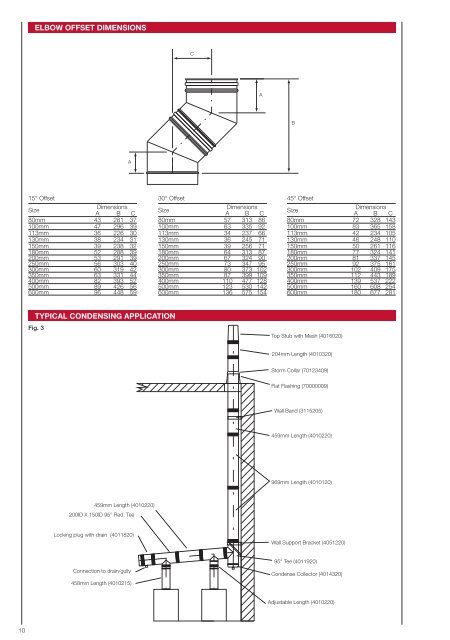
ELBOW OFFSET DIMENSIONSCABA15° OffsetSizeDimensionsA B C80mm 43 281 37100mm 47 296 39113mm 36 226 30130mm 38 234 31150mm 39 238 32180mm 52 288 39200mm 53 291 39250mm 56 303 40300mm 60 319 42350mm 63 331 44400mm 82 393 52500mm 89 426 56600mm 96 448 5930° OffsetSizeDimensionsA B C80mm 57 313 86100mm 63 335 92113mm 34 237 66130mm 36 245 71150mm 39 256 71180mm 64 313 87200mm 67 324 90250mm 73 347 95300mm 80 373 102350mm 87 399 109400mm 110 477 128500mm 123 530 142600mm 136 575 15445° OffsetSizeDimensionsA B C80mm 72 328 143100mm 83 365 158113mm 42 234 105130mm 46 248 110150mm 50 261 116180mm 77 324 141200mm 81 337 145250mm 92 375 161300mm 102 409 175350mm 112 443 189400mm 139 537 222500mm 160 608 254600mm 180 677 281TYPICAL CONDENSING APPLICATIONFig. 3Top Stub with Mesh (4016020)204mm Length (4010320)Storm Collar (70123409)Flat Flashing (70000009)Wall Band (3115205)459mm Length (4010220)969mm Length (4010120)459mm Length (4010220)200ID X 150ID 95° Red. TeeLocking plug with drain (4011820)Wall Support Bracket (4051220)Connection to drain/gully458mm Length (4010215)95° Tee (4011920)Condense Collector (4014320)Adjustable Length (4010220)10
INSTALLATION INSTRUCTIONSMandatory RequirementsIn all instances the requirements of the Building Regulations mustbe complied with and the appropriate references are: DocumentJ of the DOE Building Regulations, Section F of the BuildingStandards (Scotland), Section L of the Building Regulations(Northern Ireland). Reference should also be made to the relevantBritish and European Standards governing the installation of fl ueand chimney products for the associated fuel and appliance typesas detailed:Solid Fuel and Oil Fired Applications: BS EN15287-1:2007Domestic Gas Installations: BS5440: Part 1: 2008Note: In the UK, connection to an appliance which is notconnected to the fuel supply, may be carried out by a competentperson. However, connection to an appliance that is connected tothe fuel supply must be carried out by an approved and registeredHeating Engineer, e.g. Gas Safe, HETAS (Solid Fuel) or OFTEC (Oil).General<strong>Supra</strong> must be applied such that the system complies with local/ national Building Regulations and applicable standards. Whereused on condensing appliances, the range of components willpermit deliberate drainage of condensate, either back to thecondensate removal components within the <strong>Supra</strong> System range,or through the heating appliance. No part of the fl ue systemshould be constructed to form an angle greater than 45˚ fromthe vertical. Although components are included that will permithorizontal applications, they should only be used for connectionto the appliance. Where the system is being used for a condensingapplication, it is required that sloping connections run at an angleof 5˚ from the horizontal, using the Tees, Elbows and fi ttingsdesigned for that purpose.If the system is to be used within an existing chimney or purposedesigned shaft, the range of support components will allow suchconfi gurations and can also be used to provide an independentand fully supported system both inside an outside a building.Where <strong>Supra</strong> is installed in exposed applications or where theexternal run is greater than 3.0 metres, SFL would recommend thatthe Nova SM product is used. Nova SM is a twin wall insulatedstainless steel system offering a high degree protection againstfreezing. Adaptors are available to allow conversion between thetwo products (See Page 7).JointingThe <strong>Supra</strong> system is jointed by pushing the male end into thefemale end of the proceeding component, and then applying aLocking Band. The Locking Band must be installed so that thetoggle is only closed from left to right. See Fig. 4.Ensure that both ends of the connecting joint are clean and free ofdirt / grit.Fig. 5 Standard Joint detailAdjustable LengthThe Adjustable Length consists of a section of SUPRA, the lowernon-beaded end of which is designed preferably to be located intoa standard length. It can also be inserted into the female end ofother components, but however applied, must engage to a depthequivalent to at least half of the diameter of the SUPRA being used.Where pressure and moisture resistance are required a specialLocking Band & Seal is required to make the joint.On standard <strong>Supra</strong>, the Adjustable Length is supplied completewith a special Locking Band & Seal. For <strong>Supra</strong> 1.0mm, thespecial Locking Band & Seal MUST be ordered separately.Fig. 6Jointdetailand sealprofi leLockingBandSealGas DirectionMale endFemalesocketLock Band detail for the Adjustable Lengthfor Condensing ApplicationsThe Lock Band isprofi led such thatwhen used with theAdjustable Length,the toggle must snapto the right, NOT tothe leftGasDirectionFig. 4Note that the Locking Band hasa profi le which will only correctlylocate one way round the joint.For that reason, it MUST belocated so that the toggle is onlyclosed from left to rightSprung toggle illustratedLock Bands fi tted withthis type of toggle shouldbe adjusted so that whenthe rod end is engaged inthe strike, the lever pin isbetween 5° and 10° pastthe centre lineAdjustable Lever togglerod endLever pinThe <strong>Supra</strong> 0.5mm product is supplied complete with factorybonded Elastomer Seals.For 1mm <strong>Supra</strong>, depending on the application, the joint can bemade pressure and moisture resistant using an Elastomer Sealwhich must be ordered separately. The Elastomer Seal should belocated and ideally bonded as shown in Fig. 5Note that the lips of the seal must point in one direction as shown.Because the seal is designed to provide a secure grip to the maleend of the component, SFL Seal Lubricating gel should be used tofacilitation ease of installation and to prevent potential damage ofthe seal during installation.5° - 10°Fig. 6 illustrates the joint detail. Locate the seal over the socketedfemale end of the length or component female end before insertingthe male end, and then pull the seal up so that the angled notchon its inside locates over the turned end of the female socket asshown. To facilitate easier assembly, apply SFL Joint Lubricantto the seal prior to installation. The Lock Band has two designsof toggle, either spring or adjustable. If using the band with theadjustable toggle, it should be tensioned as shown in Fig. 6 Notethat whichever type is applied, the profi le of the Lock Band issuch that it must only be applied one way round. If it is locatedincorrectly, the joint will be both insecure and inadequately sealed.11