Holographic generation and orbital angular momentum of high ...
Holographic generation and orbital angular momentum of high ...
Holographic generation and orbital angular momentum of high ...

Create successful ePaper yourself
Turn your PDF publications into a flip-book with our unique Google optimized e-Paper software.
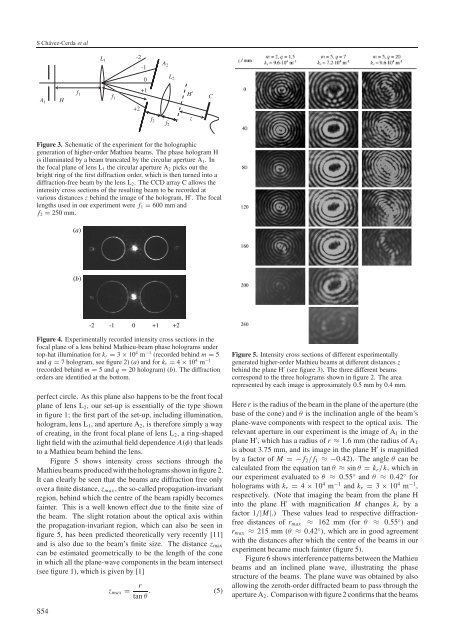
SChávez-Cerda et alA 1Hf 1L 1A 2-2-1f 20L 2+1f 1+2f 2H′zCFigure 3. Schematic <strong>of</strong> the experiment for the holographic<strong>generation</strong> <strong>of</strong> <strong>high</strong>er-order Mathieu beams. The phase hologram His illuminated by a beam truncated by the circular aperture A 1 .Inthe focal plane <strong>of</strong> lens L 1 the circular aperture A 2 picks out thebright ring <strong>of</strong> the first diffraction order, which is then turned into adiffraction-free beam by the lens L 2 . The CCD array C allows theintensity cross sections <strong>of</strong> the resulting beam to be recorded atvarious distances z behind the image <strong>of</strong> the hologram, H ′ . The focallengths used in our experiment were f 1 = 600 mm <strong>and</strong>f 2 = 250 mm.(a)(b)-2 -1 0 +1 +2Figure 4. Experimentally recorded intensity cross sections in thefocal plane <strong>of</strong> a lens behind Mathieu-beam phase holograms undertop-hat illumination for k r = 3 × 10 4 m −1 (recorded behind m = 5<strong>and</strong> q = 7 hologram, see figure 2) (a) <strong>and</strong>fork r = 4 × 10 4 m −1(recorded behind m = 5<strong>and</strong>q = 20 hologram) (b). The diffractionorders are identified at the bottom.z max =rtan θ . (5) allowing the zeroth-order diffracted beam to pass through theaperture A 2 . Comparison with figure 2 confirms that the beamsFigure 5. Intensity cross sections <strong>of</strong> different experimentallygenerated <strong>high</strong>er-order Mathieu beams at different distances zbehind the plane H ′ (see figure 3). The three different beamscorrespond to the three holograms shown in figure 2. The arearepresented by each image is approximately 0.5 mm by 0.4 mm.Here r is the radius <strong>of</strong> the beam in the plane <strong>of</strong> the aperture (thebase <strong>of</strong> the cone) <strong>and</strong> θ is the inclination angle <strong>of</strong> the beam’splane-wave components with respect to the optical axis. Therelevant aperture in our experiment is the image <strong>of</strong> A 1 in theplane H ′ , which has a radius <strong>of</strong> r ≈ 1.6 mm (the radius <strong>of</strong> A 1is about 3.75 mm, <strong>and</strong> its image in the plane H ′ is magnifiedby a factor <strong>of</strong> M =−f 2 /f 1 ≈−0.42). The angle θ can becalculated from the equation tan θ ≈ sin θ = k r /k, whichinour experiment evaluated to θ ≈ 0.55 ◦ <strong>and</strong> θ ≈ 0.42 ◦ forholograms with k r = 4 × 10 4 m −1 <strong>and</strong> k r = 3 × 10 4 m −1 ,respectively. (Note that imaging the beam from the plane Hinto the plane H ′ with magnification M changes k r by afactor 1/|M|.) These values lead to respective diffractionfreedistances <strong>of</strong> r max ≈ 162 mm (for θ ≈ 0.55 ◦ )<strong>and</strong>r max ≈ 215 mm (θ ≈ 0.42 ◦ ), which are in good agreementwith the distances after which the centre <strong>of</strong> the beams in ourexperiment became much fainter (figure 5).Figure 6 shows interference patterns between the Mathieubeams <strong>and</strong> an inclined plane wave, illustrating the phasestructure <strong>of</strong> the beams. The plane wave was obtained by alsoperfect circle. As this plane also happens to be the front focalplane <strong>of</strong> lens L 2 , our set-up is essentially <strong>of</strong> the type shownin figure 1; the first part <strong>of</strong> the set-up, including illumination,hologram, lens L 1 , <strong>and</strong> aperture A 2 , is therefore simply a way<strong>of</strong> creating, in the front focal plane <strong>of</strong> lens L 2 , a ring-shapedlight field with the azimuthal field dependence A(φ) that leadsto a Mathieu beam behind the lens.Figure 5 shows intensity cross sections through theMathieu beams produced with the holograms shown in figure 2.It can clearly be seen that the beams are diffraction free onlyover a finite distance, z max , the so-called propagation-invariantregion, behind which the centre <strong>of</strong> the beam rapidly becomesfainter. This is a well known effect due to the finite size <strong>of</strong>the beam. The slight rotation about the optical axis withinthe propagation-invariant region, which can also be seen infigure 5, has been predicted theoretically very recently [11]<strong>and</strong> is also due to the beam’s finite size. The distance z maxcan be estimated geometrically to be the length <strong>of</strong> the conein which all the plane-wave components in the beam intersect(see figure 1), which is given by [1]S54