2003 MY OBD System Operation Summary for Gasoline Engines
2003 MY OBD System Operation Summary for Gasoline Engines
2003 MY OBD System Operation Summary for Gasoline Engines
- No tags were found...

You also want an ePaper? Increase the reach of your titles
YUMPU automatically turns print PDFs into web optimized ePapers that Google loves.
4R70W (RWD) Transmission ..........................................................................78AX4S/4F50N (AX4N) (FWD) Transmission....................................................79CD4E (FWD) Transmission .............................................................................805R44E (RWD) Transmission............................................................................815R55E (RWD) Transmission............................................................................825R55S (RWD) Transmission – without ETC...................................................835R55S (RWD) Transmission – with ETC........................................................854R100 (E4OD) (RWD) Transmission..............................................................875R110W (RWD) Transmission ........................................................................884F27E (FN) (FWD) Transmission....................................................................90On Board Diagnostic Executive .......................................................................91Exponentially Weighted Moving Average .......................................................92I/M Readiness Code .........................................................................................94Catalyst Temperature Model............................................................................95Serial Data Link MIL Illumination .....................................................................95FORD MOTOR COMPANY REVISION DATE: DECEMBER 19, 2002 PAGE 2 OF 95
Introduction – <strong>OBD</strong>-I and <strong>OBD</strong>-II<strong>OBD</strong>-II <strong>System</strong>sCali<strong>for</strong>nia <strong>OBD</strong>-II applies to all gasoline engine vehicles up to 14,000 lbs. Gross Vehicle Weight Rating (GVWR)starting in the 1996 <strong>MY</strong> and all diesel engine vehicles up to 14,000 lbs. GVWR starting in the 1997 <strong>MY</strong>."Green States" are states in the Northeast that chose to adopt Cali<strong>for</strong>nia emission regulations, starting in the 1998<strong>MY</strong>. At this time, Massachusetts, New York, Vermont and Maine are Green States. Green States receiveCali<strong>for</strong>nia-certified vehicles <strong>for</strong> passenger cars and light trucks up to 6,000 lbs. GVWR.The National LEV program (NLEV) requires compliance with Cali<strong>for</strong>nia <strong>OBD</strong>-II, including 0.020" evaporativesystem monitoring requirements. The NLEV program apply to passenger cars and light trucks up to 6,000 lbs.GVWR nation-wide from 2001 <strong>MY</strong> through <strong>2003</strong> <strong>MY</strong>Federal <strong>OBD</strong> applies to all gasoline engine vehicles up to 8,500 lbs. GVWR starting in the 1996 <strong>MY</strong> and all dieselengine vehicles up to 8,500 lbs. GVWR starting in the 1997 <strong>MY</strong>.<strong>OBD</strong>-II system implementation and operation is described in the remainder of this document.<strong>OBD</strong>-I <strong>System</strong>sIf a vehicle is not required to comply with <strong>OBD</strong>-II requirements, it utilizes an <strong>OBD</strong>-I system. <strong>OBD</strong>-I systems areused on all over 8,500 lbs. GVWR Federal truck calibrations. With the exception of the 1996 <strong>MY</strong> carryover EEC-IV<strong>OBD</strong>-I systems, Federal > 8,500 lbs. <strong>OBD</strong>-I vehicles use that same PCM, J1850 serial data communication link,J1962 Data Link Connector, and PCM software as the corresponding <strong>OBD</strong>-II vehicle. The only difference is thepossible removal of the rear oxygen sensor(s), fuel tank pressure sensor, canister vent solenoid, and a differentPCM calibration.The following list indicate what monitors and functions have been altered <strong>for</strong> <strong>OBD</strong>-I calibrations:Monitor / FeatureCatalyst MonitorMisfire MonitorOxygen Sensor MonitorCalibrationNot required, monitor calibrated out, rear O2 sensors may be deleted.Calibrated in <strong>for</strong> service, all DTCs are non-MIL. Catalyst damage misfire criteriacalibrated out, emission threshold criteria set to 4%, enabled between 150 o F and 220o F, 254 sec start-up delay.Rear O2 sensor test calibrated out, rear O2 sensors may be deleted, front O2 sensorresponse test calibrated out, O2 heater current test calibrated out prior to 2002 <strong>MY</strong>, O2heater voltage test used <strong>for</strong> all model years.Same as <strong>OBD</strong>-II calibration except that P0402 test uses slightly higher threshold.EGR MonitorFuel <strong>System</strong> Monitor Same as <strong>OBD</strong>-II calibration starting in 2002 <strong>MY</strong>, earlier calibrations used +/- 40%thresholds.Secondary Air Monitor Functional (low flow) test calibrated out, circuit codes are same as <strong>OBD</strong>-II calibration.Evap <strong>System</strong> Monitor Evap system leak check calibrated out, fuel level input circuit checks retained as non-MIL. Fuel tank pressure sensor and canister vent solenoid may be deleted.PCV MonitorSame hardware and function as <strong>OBD</strong>-II.Thermostat Monitor Thermostat monitor calibrated out.Comprehensive All circuit checks same as <strong>OBD</strong>-II. Some rationality and functional tests calibrated out.Component Monitor (MAF/TP rationality, IAC functional)Communication Same as <strong>OBD</strong>-II, all generic and enhanced scan tool modes work the same as <strong>OBD</strong>-IIProtocol and DLC but reflect the <strong>OBD</strong>-I calibration that contains fewer supported monitors. "<strong>OBD</strong>MIL ControlSupported" PID indicates <strong>OBD</strong>-I.Same as <strong>OBD</strong>-II, it takes 2 driving cycles to illuminate the MIL.FORD MOTOR COMPANY REVISION DATE: DECEMBER 19, 2002 PAGE 3 OF 95
Catalyst Efficiency MonitorThe Catalyst Efficiency Monitor uses an oxygen sensor be<strong>for</strong>e and after the catalyst to infer the hydrocarbonefficiency based on oxygen storage capacity of the ceria and precious metals in the washcoat. Under normal,closed-loop fuel conditions, high efficiency catalysts have significant oxygen storage. This makes the switchingfrequency of the rear HO2S very slow and reduces the amplitude of those switches as compared to the switchingfrequency and amplitude of the front HO2S. As catalyst efficiency deteriorates due to thermal and/or chemicaldeterioration, its ability to store oxygen declines. The post-catalyst HO2S signal begins to switch more rapidly withincreasing amplitude, approaching the switching frequency and amplitude of the pre-catalyst HO2S. Thepredominant failure mode <strong>for</strong> high mileage catalysts is chemical deterioration (phosphorus deposition on the frontbrick of the catalyst), not thermal deterioration.All applications utilize an FTP-based (Federal Test Procedure) catalyst monitor. This simply means that thecatalyst monitor must run during a standard FTP emission test as opposed to the 20-second steady-state catalystmonitor used in 1994 through some 1996 vehicles. Two slightly different versions of the catalyst monitor are used<strong>for</strong> 2001 <strong>MY</strong> and beyond vehicles. Both versions will continue to be used in subsequent model years.Switch Ratio Method (1996 - <strong>2003</strong>)In order to assess catalyst oxygen storage, the monitor counts front and rear HO2S switches during part-throttle,closed-loop fuel conditions after the engine is warmed-up and inferred catalyst temperature is within limits. Frontswitches are accumulated in up to nine different air mass regions or cells although 3 air mass regions is typical.Rear switches are counted in a single cell <strong>for</strong> all air mass regions. When the required number of front switches hasaccumulated in each cell (air mass region), the total number of rear switches is divided by the total number of frontswitches to compute a switch ratio. A switch ratio near 0.0 indicates high oxygen storage capacity, hence high HCefficiency. A switch ratio near 1.0 indicates low oxygen storage capacity, hence low HC efficiency. If the actualswitch ratio exceeds the threshold switch ratio, the catalyst is considered failed.Index Ratio Method (some 2001 and beyond)In order to assess catalyst oxygen storage, the catalyst monitor counts front HO2S switches during part-throttle,closed-loop fuel conditions after the engine is warmed-up and inferred catalyst temperature is within limits. Frontswitches are accumulated in up to three different air mass regions or cells. While catalyst monitoring entryconditions are being met, the front and rear HO2S signal lengths are continually being calculated. When therequired number of front switches has accumulated in each cell (air mass region), the total signal length of the rearHO2S is divided by the total signal length of front HO2S to compute a catalyst index ratio. An index ratio near 0.0indicates high oxygen storage capacity, hence high HC efficiency. An index ratio near 1.0 indicates low oxygenstorage capacity, hence low HC efficiency. If the actual index ratio exceeds the threshold index ratio, the catalyst isconsidered failed.General Catalyst Monitor <strong>Operation</strong>If the catalyst monitor does not complete during a particular driving cycle, the already-accumulated switch/signallengthdata is retained in Keep Alive Memory and is used during the next driving cycle to allow the catalyst monitora better opportunity to complete, even under short or transient driving conditions.Rear HO2S sensors can be located in various ways to monitor different kinds of exhaust systems. In-line enginesand many V-engines are monitored by individual bank. A rear HO2S sensor is used along with the front, fuelcontrolHO2S sensor <strong>for</strong> each bank. Two sensors are used on an in-line engine; four sensors are used on a V-engine. Some V-engines have exhaust banks that combine into a single underbody catalyst. These systems arereferred to as Y-pipe systems. They use only one rear HO2S sensor along with the two front, fuel-control HO2Ssensors. Y-pipe system use three sensors in all. For Y-pipe systems, the two front HO2S sensor signals arecombined by the software to infer what the HO2S signal would have been in front of the monitored catalyst. Theinferred front HO2S signal and the actual single, rear HO2S signal is then used to calculate the switch ratio.FORD MOTOR COMPANY REVISION DATE: DECEMBER 19, 2002 PAGE 4 OF 95
Most vehicles that are part of the “LEV” catalyst monitor phase-in will monitor less than 100% of the catalystvolume – often the first catalyst brick of the catalyst system. Partial volume monitoring is done on LEV and ULEVvehicles in order to meet the 1.75 * emission-standard. The rationale <strong>for</strong> this practice is that the catalysts nearestthe engine deteriorate first, allowing the catalyst monitor to be more sensitive and illuminate the MIL properly atlower emission standards.Many applications that utilize partial-volume monitoring place the rear HO2S sensor after the first light-off catalystcan or, after the second catalyst can in a three-can per bank system. (A few applications placed the HO2S in themiddle of the catalyst can, between the first and second bricks.)Index ratios <strong>for</strong> ethanol (Flex fuel) vehicles vary based on the changing concentration of alcohol in the fuel. Themalfunction threshold typically increases as the percent alcohol increases. For example, a malfunction threshold of0.5 may be used at E10 (10% ethanol) and 0.9 may be used at E85 (85% ethanol). The malfunction thresholds arethere<strong>for</strong>e adjusted based on the % alcohol in the fuel. (Note: Normal gasoline is allowed to contain up to 10%ethanol (E10)).All vehicles employ an Exponentially Weighted Moving Average (EWMA) algorithm to improve the robustness ofthe FTP catalyst monitor. During normal customer driving, a malfunction will illuminate the MIL, on average, in 3 to6 driving cycles. If KAM is reset (battery disconnected), a malfunction will illuminate the MIL in 2 driving cycles. Seethe section on EWMA <strong>for</strong> additional in<strong>for</strong>mation.CATALYST MONITOR OPERATION:DTCs P0420 Bank 1 (or Y-pipe), P0430 Bank 2Monitor executionMonitor SequenceSensors OKMonitoring Durationonce per driving cycleHO2S response test complete and no DTCs (P0133/P0153) prior tocalculating switch ratio, no SAIR pump stuck on DTCs (P0412/P1414), noevap leak check DTCs (P0442/P0456)ECT, IAT, TP, VSS, CKPApproximately 700 seconds during appropriate FTP conditions(approximately 100 to 200 oxygen sensor switches are collected)TYPICAL SWITCH RATIO CATALYST MONITOR ENTRY CONDITIONS:Entry condition Minimum MaximumTime since engine start-up (70 o F start)330 secondsEngine Coolant Temp 170 o F 230 o FIntake Air Temp 20 o F 180 o FEngine Load 10%Throttle Position Part Throttle Part ThrottleTime since entering closed loop fuel30 secVehicle Speed 5 mph 70 mphInferred Catalyst Mid-bed Temperature900 o FEGR flow (Note: an EGR fault disables EGR) 1% 12%Fuel Level 15%Steady Air Mass Flow <strong>for</strong> each Air Mass cell (typically three cells) 1.0 lb/min 5.0 lb/min(Note: FTP cycle is biased towards the low air mass range, 25 - 35 mph steady state driving must beper<strong>for</strong>med to complete the monitor)FORD MOTOR COMPANY REVISION DATE: DECEMBER 19, 2002 PAGE 5 OF 95
TYPICAL INDEX RATIO CATALYST MONITOR ENTRY CONDITIONS:Entry condition Minimum MaximumTime since engine start-up (70 o F start)330 secondsEngine Coolant Temp 170 o F 230 o FIntake Air Temp 20 o F 180 o FTime since entering closed loop fuelInferred Rear HO2S sensor Temperature30 sec900 o FEGR flow (Note: an EGR fault disables EGR) 1% 12%Throttle Position Part Throttle Part ThrottleRate of Change of Throttle Position 0.2 volts /0.050 secVehicle Speed 5 mph 70 mphFuel Level 15%First Air Mass Cell 1.0 lb/min 2.0 lb/minEngine RPM <strong>for</strong> first air mass cell 1,000 rpm 1,300 rpmEngine Load <strong>for</strong> first air mass cell 15% 35%Monitored catalyst mid-bed temp. (inferred) <strong>for</strong> first air mass cell 850 o F 1,200 o FNumber of front O2 switches required <strong>for</strong> first air mass cell 50Second Air Mass Cell 2.0 lb/min 3.0 lb/minEngine RPM <strong>for</strong> second air mass cell 1,200 rpm 1,500 rpmEngine Load <strong>for</strong> second air mass cell 20% 35%Monitored catalyst mid-bed temp. (inferred) <strong>for</strong> second air mass cell 900 o F 1,250 o FNumber of front O2 switches required <strong>for</strong> second air mass cell 70Third Air Mass Cell 3.0 lb/min 4.0 lb/minEngine RPM <strong>for</strong> third air mass cell 1,300 rpm 1,600 rpmEngine Load <strong>for</strong> third air mass cell 20% 40%Monitored catalyst mid-bed temp. (inferred) <strong>for</strong> third air mass cell 950 o F 1,300 o FNumber of front O2 switches required <strong>for</strong> third air mass cell 30(Note: Engine rpm and load values <strong>for</strong> each air mass cell can vary as a function of the power-to-weight ratioof the engine, transmission and axle gearing and tire size.)TYPICAL MALFUNCTION THRESHOLDS:Rear-to-front O2 sensor switch/index-ratio > 0.75 (bank monitor)Rear-to-front O2 sensor switch/index-ratio > 0.60 (Y-pipe monitor)Rear-to-front O2 sensor switch/index ratio > 0.50 <strong>for</strong> E10 to > 0.90 <strong>for</strong> E85 (flex fuel vehicles)FORD MOTOR COMPANY REVISION DATE: DECEMBER 19, 2002 PAGE 6 OF 95
J1979 CATALYST MONITOR MODE $06 DATATest ID Comp ID Description <strong>for</strong> J1850 Units$10 $11 Bank 1 switch-ratio and max. limit unitless$10 $21 Bank 2 switch-ratio and max. limit unitless$10 $10 Bank 1 index-ratio and max. limit unitless$10 $20 Bank 2 index-ratio and max. limit unitlessMonitor ID Test ID Description <strong>for</strong> CAN$21 $80 Bank 1 index-ratio and max. limit unitless$22 $80 Bank 2 index-ratio and max. limit unitlessConversion <strong>for</strong> J1850 Test ID $10: multiply by 0.0156 to get a value from 0 to 1.0** NOTE: In this document, a monitor or sensor is considered OK if there are no DTCs stored <strong>for</strong> that componentor system at the time the monitor is running.FORD MOTOR COMPANY REVISION DATE: DECEMBER 19, 2002 PAGE 7 OF 95
Misfire MonitorThere are two different misfire monitoring technologies used in the <strong>2003</strong> <strong>MY</strong>. They are Low Data Rate (LDR) andHigh Data Rate (HDR). The LDR system is capable of meeting the FTP monitoring requirements on mostengines and is capable of meeting “full-range” misfire monitoring requirements on 4-cylinder engines. The HDRsystem is capable of meeting “full-range” misfire monitoring requirements on 6 and 8 cylinder engines. HDR isbeing phased in on these engines to meet the” full-range” misfire phase-in requirements specified in the <strong>OBD</strong>-IIregulations. By the <strong>2003</strong> <strong>MY</strong> all engines except the 6.8L V-10 will be “full-range” capable. <strong>2003</strong> <strong>MY</strong> software hasbeen modified to allow <strong>for</strong> detection of any misfires that occur 6 engine revolutions after initially cranking theengine. This meets the new <strong>OBD</strong>-II requirement to identify misfires within 2 engine revolutions after exceedingthe warm drive, idle rpm.Low Data Rate <strong>System</strong>The LDR Misfire Monitor uses a low-data-rate crankshaft position signal, (i.e. one position reference signal at 10deg BTDC <strong>for</strong> each cylinder event). The PCM calculates crankshaft rotational velocity <strong>for</strong> each cylinder from thiscrankshaft position signal. The acceleration <strong>for</strong> each cylinder can then be calculated using successive velocityvalues. The changes in overall engine rpm are removed by subtracting the median engine acceleration over acomplete engine cycle. The resulting deviant cylinder acceleration values are used in evaluating misfire in the“General Misfire Algorithm Processing” section below.“Profile correction” software is used to “learn” and correct <strong>for</strong> mechanical inaccuracies in crankshaft tooth spacingunder de-fueled engine conditions (requires three 60 to 40 mph no-braking decels after Keep Alive Memory hasbeen reset). These learned corrections improve the high-rpm capability of the monitor <strong>for</strong> most engines. Themisfire monitor is not active until a profile has been learned.High Data Rate <strong>System</strong>The HDR Misfire Monitor uses a high data rate crankshaft position signal, (i.e. 18 position references percrankshaft revolution [20 on a V-10]). This high-resolution signal is processed using two different algorithms. Thefirst algorithm, called pattern cancellation, is optimized to detect low rates of misfire. The algorithm learns thenormal pattern of cylinder accelerations from the mostly good firing events and is then able to accurately detectdeviations from that pattern. The second algorithm is optimized to detect “hard” misfires, i.e. one or morecontinuously misfiring cylinders. This algorithm filters the high-resolution crankshaft velocity signal to remove someof the crankshaft torsional vibrations that degrade signal to noise. This significantly improves detection capability <strong>for</strong>continuous misfires. Both algorithms produce a deviant cylinder acceleration value, which is used in evaluatingmisfire in the “General Misfire Algorithm Processing” section below.Due to the high data processing requirements, the HDR algorithms could not be implemented in the PCMmicroprocessor. They are implemented in a separate chip in the PCM called an “AICE” chip. The PCMmicroprocessor communicates with the AICE chip using a dedicated serial communication link. The output of theAICE chip (the cylinder acceleration values) is sent to the PCM microprocessor <strong>for</strong> additional processing asdescribed below. Lack of serial communication between the AICE chip and the PCM microprocessor, or aninability to synchronize the crank or cam sensors inputs sets a P1309 DTC. For <strong>2003</strong> <strong>MY</strong> software, the P1309DTC is being split into two separate DTCs. A P0606 will be set if there is a lack of serial communication betweenthe AICE chip and the PCM microprocessor. A P1336 will be set if there is an inability to synchronize the crank orcam sensors inputs. This change was made to improve serviceability. A P0606 generally results in PCMreplacement while a P1336 points to a cam sensor that is out of synchronization with the crank.“Profile correction” software is used to “learn” and correct <strong>for</strong> mechanical inaccuracies in crankshaft tooth spacingunder de-fueled engine conditions (requires three 60 to 40 mph no-braking decels after Keep Alive Memory hasbeen reset). If KAM has been reset, the PCM microprocessor initiates a special routine which computes correctionfactors <strong>for</strong> each of the 18 (or 20) position references and sends these correction factors back to the AICE chip tobe used <strong>for</strong> subsequent misfire signal processing. These learned corrections improve the high rpm capability of themonitor. The misfire monitor is not active until a profile has been learned.FORD MOTOR COMPANY REVISION DATE: DECEMBER 19, 2002 PAGE 8 OF 95
Generic Misfire Algorithm ProcessingThe acceleration that a piston undergoes during a normal firing event is directly related to the amount of torque thatcylinder produces. The calculated piston/cylinder acceleration value(s) are compared to a misfire threshold that iscontinuously adjusted based on inferred engine torque. Deviant accelerations exceeding the threshold areconditionally labeled as misfires.The calculated deviant acceleration value(s) are also evaluated <strong>for</strong> noise. Normally, misfire results in a nonsymmetricalloss of cylinder acceleration. Mechanical noise, such as rough roads or high rpm/light load conditions,will produce symmetrical acceleration variations. Cylinder events that indicate excessive deviant accelerations ofthis type are considered noise. Noise-free deviant acceleration exceeding a given threshold is labeled a misfire.The number of misfires are counted over a continuous 200 revolution and 1000 revolution period. (The revolutioncounters are not reset if the misfire monitor is temporarily disabled such as <strong>for</strong> negative torque mode, etc.) At theend of the evaluation period, the total misfire rate and the misfire rate <strong>for</strong> each individual cylinder is computed. Themisfire rate evaluated every 200 revolution period (Type A) and compared to a threshold value obtained from anengine speed/load table. This misfire threshold is designed to prevent damage to the catalyst due to sustainedexcessive temperature (1600°F <strong>for</strong> Pt/Pd/Rh conventional washcoat, 1650°F <strong>for</strong> Pt/Pd/Rh advanced washcoat and1800°F <strong>for</strong> Pd-only high tech washcoat). If the misfire threshold is exceeded and the catalyst temperature modelcalculates a catalyst mid-bed temperature that exceeds the catalyst damage threshold, the MIL blinks at a 1 Hzrate while the misfire is present. If the threshold is again exceeded on a subsequent driving cycle, the MIL isilluminated. If a single cylinder is indicated to be consistently misfiring in excess of the catalyst damage criteria, thefuel injector to that cylinder may be shut off <strong>for</strong> a period of time to prevent catalyst damage. Up to two cylindersmay be disabled at the same time. This fuel shut-off feature is used on many 8-cylinder engine and some 6-cylinder engines. It is never used on a 4-cylinder engine. Next, the misfire rate is evaluated every 1000 rev periodand compared to a single (Type B) threshold value to indicate an emission-threshold malfunction, which can beeither a single 1000 rev exceedence from startup or four subsequent 1000 rev exceedences on a drive cycle afterstart-up. Many <strong>2003</strong> <strong>MY</strong> vehicles will set a P0316 DTC if the Type B malfunction threshold is exceeded during thefirst 1,000 revs after engine startup. This DTC is stored in addition to the normal P03xx DTC that indicates themisfiring cylinder(s).Profile Correction"Profile correction" software is used to "learn" and correct <strong>for</strong> mechanical inaccuracies in the crankshaft positionwheel tooth spacing. Since the sum of all the angles between crankshaft teeth must equal 360 o , a correction factorcan be calculated <strong>for</strong> each misfire sample interval that makes all the angles between individual teeth equal. Toprevent any fueling or combustion differences from affecting the correction factors, learning is done during decelfuelcutout.The correction factors are learned during closed-throttle, non-braking, de-fueled decelerations in the 60 to 40 mphrange after exceeding 60 mph (likely to correspond to a freeway exit condition). In order to minimize the learningtime <strong>for</strong> the correction factors, a more aggressive decel-fuel cutout strategy may be employed when the conditions<strong>for</strong> learning are present. The corrections are typically learned in a single deceleration, but can be learned during upto 3 such decelerations. The "mature" correction factors are the average of a selected number of samples. A lowdata rate misfire system will typically learn 4 such corrections in this interval, while a high data rate system will learn36 or 40 in the same interval (data is actually processed in the AICE chip). In order to assure the accuracy of thesecorrections, a tolerance is placed on the incoming values such that an individual correction factor must berepeatable within the tolerance during learning This is to reduce the possibility of learning corrections on roughroad conditions which could limit misfire detection capability.Since inaccuracies in the wheel tooth spacing can produce a false indication of misfire, the misfire monitor is notactive until the corrections are learned. In the event of battery disconnection or loss of Keep Alive Memory thecorrection factors are lost and must be relearned. If the software is unable to learn a profile after three 60 to 40mph decels, a P0315 DTC is set.FORD MOTOR COMPANY REVISION DATE: DECEMBER 19, 2002 PAGE 9 OF 95
Misfire Monitor <strong>Operation</strong>:DTCsMonitor executionMonitor SequenceSensors OKMonitoring DurationP0300 to P0310 (general and specific cylinder misfire)P1309 (no cam/crank synchronization, AICE chip malfunction)P1336 (no cam/crank synchronization)P0606 (AICE chip malfunction)P0315 (unable to learn profile)P0316 (misfire during first 1,000 revs after start-up)Continuous, misfire rate calculated every 200 or 1000 revsNoneCKP, CMPEntire driving cycle (see disablement conditions below)Typical misfire monitor entry conditions:Entry condition Minimum MaximumTime since engine start-up 0 seconds 0 secondsEngine Coolant Temperature 20 o F 250 o FRPM Range (Full-Range Misfire certified, with 2 revdelay)Profile correction factors learned in KAM2 revs after exceeding150 rpm below “drive”idle rpmYesFuel tank level 15%redline on tach or fuelcutoffTypical misfire temporary disablement conditions:Temporary disablement conditions:Closed throttle decel (negative torque, engine being driven)Fuel shut-off due to vehicle-speed limiting or engine-rpm limiting modeAccessory load-state change (A/C, power steering), (used on some applications)High rate of change of torque (heavy throttle tip-in or tip out)Typical misfire monitor malfunction thresholds:Type A (catalyst damaging misfire rate): misfire rate is an rpm/load table ranging from 40% at idle to 4% athigh rpm and loadsType B (emission threshold rate): 1% to 2%FORD MOTOR COMPANY REVISION DATE: DECEMBER 19, 2002 PAGE 10 OF 95
J1979 Misfire Mode $06 DataTest ID Comp ID Description <strong>for</strong> J1850 Units$50 $00 Total engine misfire and emission threshold misfire rate (updatedevery 1,000 revolutions)$53 $00 - $0A Cylinder-specific misfire and catalyst damage threshold misfire rate(either cat damage or emission threshold) (updated when DTC set orclears)$54 $00 Highest catalyst-damage misfire and catalyst damage threshold misfirerate (updated when DTC set or clears)$55 $00 Highest emission-threshold misfire and emission threshold misfire rate(updated when DTC set or clears)$56 $00 Cylinder events tested and number of events required <strong>for</strong> a 1000 revtestpercentpercentpercentpercenteventsMonitor ID Test ID Description <strong>for</strong> CANA1 $80 Total engine misfire and catalyst damage misfire rate (updated every200 revolutions)A1 $81 Total engine misfire and emission threshold misfire rate (updatedevery 1,000 revolutions)A1 $82 Highest catalyst-damage misfire and catalyst damage threshold misfirerate (updated when DTC set or clears)A1 $83 Highest emission-threshold misfire and emission threshold misfire rate(updated when DTC set or clears)A1 $84 Inferred catalyst mid-bed temperaturepercentpercentpercentpercento CA2 – AD $0B EWMA misfire counts <strong>for</strong> last 10 driving cycles eventsA2 – AD $0C Misfire counts <strong>for</strong> last/current driving cycle eventsA2 – AD $80 Cylinder X misfire rate and catalyst damage misfire rate (updatedevery 200 revolutions)A2 – AD $81 Cylinder X misfire rate and emission threshold misfire rate (updatedevery 1,000 revolutions)percentpercentConversion <strong>for</strong> Test IDs $50 through $55: multiply by 0.000015 to get percentConversion <strong>for</strong> Test ID $56: multiply by 1 to get ignition eventsFORD MOTOR COMPANY REVISION DATE: DECEMBER 19, 2002 PAGE 11 OF 95
AIR <strong>System</strong> MonitorThe secondary air systems typically utilize an electric air pump as well as one or two electrically controlled checkvalves to deliver air into the exhaust manifold.The only vehicle which uses secondary air in the <strong>2003</strong> <strong>MY</strong> is the 2.3L PZEV Focus. The Focus uses a systemwith ported air. This means that airflow is delivered to each individual exhaust port. The secondary air pump isenergized immediately after start-up while the fuel system is in open loop. After the O2 sensors warm up, thesecondary air pump continues to be energized while the fuel system goes into closed loop fuel. The secondary airsystem continues to run in closed loop fuel until the air pump is de-energized.The AIR pump flow check monitors the HO2S signal at idle to determine if secondary air is being delivered intothe exhaust system. The air/fuel ratio is commanded open-loop rich, the AIR pump is turned on and the timerequired <strong>for</strong> the HO2S signal to go lean is monitored. If the HO2S signal does not go lean within the allowabletime limit, a low/no flow malfunction is indicated. (P0411)The electric air pump draws high current and must be energized through a separate relay. Both the primary andsecondary circuits are checked <strong>for</strong> opens and shorts. First, the output driver within the PCM (primary circuit) ischecked <strong>for</strong> circuit continuity (P0412). This circuit energizes the relay and the control valve(s). Next, a feedbackcircuit from the secondary side of the relay to the PCM is used to check secondary circuit continuity (P1413,P1414).FORD MOTOR COMPANY REVISION DATE: DECEMBER 19, 2002 PAGE 13 OF 95
AIR Monitor <strong>Operation</strong>:DTCsMonitor executionMonitor SequenceSensors OKMonitoring DurationP0411 functional check, P0412, P1413, P1414 circuit checksFunctional - once per driving cycle, circuit checks - continuousOxygen sensor monitor complete and OKECT, IAT, no fuel system DTCs20 seconds at idleTypical AIR functional check entry conditions:Entry condition Minimum MaximumTime since engine start-upEngine Coolant Temperature600 seconds150 o FShort Term Fuel Trim not too lean 5.0%Fuel Tank Pressure4.5 in H 2 OClosed Throttle at idle rpm at idle rpmPurge Duty Cycle 20%Purge Fuel Flow 0 lb/min 0.2 lb/minBattery Voltage11 voltsNote: No P0411 DTC is stored if IAT < 20 o F at the start of the functional test although the test runs.(Precludes against identifying a temporary, frozen check valve.)Typical AIR functional check malfunction thresholds:Minimum time allowed <strong>for</strong> HO2S sensor to indicate lean: < 4 secondsJ1979 Secondary Air Mode $06 DataTest ID Comp ID Description <strong>for</strong> J1850 Units$30 $11 HO2S11 voltage <strong>for</strong> upstream flow test and rich limit volts$30 $21 HO2S21 voltage <strong>for</strong> upstream flow test and rich limit volts$31 $00 HO2S lean time <strong>for</strong> upstream flow test and time limit secondsMonitor ID Test ID Description <strong>for</strong> CAN Units$71 $80 HO2S11 voltage <strong>for</strong> upstream flow test and rich limit volts$71 $81 HO2S21 voltage <strong>for</strong> upstream flow test and rich limit volts$71 $82 HO2S lean time <strong>for</strong> upstream flow test and time limit secondsConversion <strong>for</strong> Test ID $30: multiply by 0.00098 to get voltsConversion <strong>for</strong> Test ID $31: multiply by 0.125 to get secondsFORD MOTOR COMPANY REVISION DATE: DECEMBER 19, 2002 PAGE 14 OF 95
EVAP <strong>System</strong> Monitor - 0.040” dia. leak checkVehicles that meet enhanced evaporative requirements utilize a vacuum-based evaporative system integritycheck. The evap system integrity check uses a Fuel Tank Pressure Transducer (FTPT), a Canister Vent Solenoid(CVS) and Fuel Level Input (FLI) along with the Vapor Management Valve (VMV) to find 0.040” diameter or largerevap system leaks.The evap system integrity test is done under conditions that minimize vapor generation and fuel tank pressurechanges due to fuel slosh since these could result in false MIL illumination. The check is run after a 6 hour coldengine soak (engine-off timer), during steady highway speeds at ambient air temperatures (inferred by IAT)between 40 and 100 o F.A check <strong>for</strong> refueling events is done at engine start. A refuel flag is set in KAM if the fuel level at start-up is at least20% greater than fuel fill at engine-off. It stays set until the evap monitor completes Phase 0 of the test asdescribed below.FORD MOTOR COMPANY REVISION DATE: DECEMBER 19, 2002 PAGE 15 OF 95
The evap system integrity test is done in four phases.(Phase 0 - initial vacuum pulldown):First, the Canister Vent Solenoid is closed to seal the entire evap system, then the VMV is opened to pull a 7"H 2 O vacuum. If the initial vacuum could not be achieved, a large system leak is indicated (P0455). This could becaused by a fuel cap that was not installed properly, a large hole, an overfilled fuel tank, disconnected/kinkedvapor lines, a Canister Vent Solenoid that is stuck open, a VMV that is stuck closed, or a disconnected/blockedvapor line between the VMV and the FTPTIf the initial vacuum could not be achieved after a refueling event, a gross leak, fuel cap off (P0457) is indicatedand the recorded minimum fuel tank pressure during pulldown is stored in KAM. A “Check Fuel Cap” light mayalso be illuminated.If the initial vacuum is excessive, a vacuum malfunction is indicated (P1450). This could be caused by kinkedvapor lines or a stuck open VMV. If a P0455, P0457, or P1450 code is generated, the evap test does notcontinue with subsequent phases of the small leak check, phases 1-4.Note: Not all vehicles will have the P0457 test or the Check Fuel Cap light implemented. These vehicles willcontinue to generate only a P0455. After the customer properly secures the fuel cap, the P0457, Check Fuel Capand/or MIL will be cleared as soon as normal purging vacuum exceeds the P0457 vacuum level stored in KAM.Phase 1 - Vacuum stabilizationIf the target vacuum is achieved, the VMV is closed and vacuum is allowed to stabilize <strong>for</strong> a fixed time. If thepressure in the tank immediately rises, the stabilization time us bypassed and Phase 2 of the test is entered.Some <strong>2003</strong> <strong>MY</strong> software has incorporated a "leaking" VMV test, which will also set a P1450 (excessive vacuum)DTC. This test is intended to identify a VMV that does not seal properly, but is not fully stuck open. If more than 1" H 2 O of additional vacuum is developed in Phase 1, the evap monitor will bypass Phase 2 and go directly toPhase 3 and open the canister vent solenoid to release the vacuum. Then, it will proceed to Phase 4, close thecanister vent solenoid and measure the vacuum that develops. If the vacuum exceeds approximately 4 " H 2 O, aP1450 DTC will be set.Phase 2 - Vacuum hold and decayNext, the vacuum is held <strong>for</strong> a calibrated time and the vacuum level is again recorded at the end of this timeperiod. The starting and ending vacuum levels are checked to determine if the change in vacuum exceeds thevacuum bleed up criteria. Fuel Level Input is used to adjust the vacuum bleed-up criteria <strong>for</strong> the appropriate fueltank vapor volume. Steady state conditions must be maintained throughout this bleed up portion of the test. Themonitor will abort if there is an excessive change in load, fuel tank pressure or fuel level input since these are allindicators of impending or actual fuel slosh. If the monitor aborts, it will attempt to run again (up to 20 or moretimes). If the vacuum bleed-up criteria is not exceeded, the small leak test is considered a pass. If the vacuumbleed-up criteria is exceeded on three successive monitoring events, a 0.040 “ dia. leak is likely and a final vaporgeneration check is done to verify the leak, phases 3-4. Excessive vapor generation can cause a false MIL.Phase 3 - Vacuum releaseThe vapor generation check is done by releasing any vacuum, then closing the VMV, waiting <strong>for</strong> a period of time,and determining if tank pressure remains low or if it is rising due to excessive vapor generationPhase 4 - Vapor generationIf the pressure rise due to vapor generation is below the threshold limit <strong>for</strong> absolute pressure and change inpressure, a P0442 DTC is stored.FORD MOTOR COMPANY REVISION DATE: DECEMBER 19, 2002 PAGE 16 OF 95
0.040” EVAP Monitor<strong>Operation</strong>:DTCsMonitor executionMonitor SequenceSensors/Components OKMonitoring DurationP0455 (gross leak),P1450 (excessive vacuum),P0457 (gross leak, cap off),P1443 (gross leak, no flow),P0442 (0.040” leak)once per driving cycleHO2S monitor completed and OKMAF, IAT, VSS, ECT, CKP, TP, FTP, VMV, CVS360 seconds (see disablement conditions below)Typical 0.040” EVAP monitor entry conditions, Phases 0 through 4:Entry condition Minimum MaximumEngine off (soak) time6 hoursTime since engine start-up 330 seconds 1800 secondsIntake Air Temp 40 o F 90 - 100 o FBARO ( 20%Change in tank pressure: > 1 “ H 2 OChange in fuel fill level: > 15%Number of aborts: > 20 (may be up to 255)Typical 0.040 EVAP monitor malfunction thresholds:P1450 (Excessive vacuum): < -8.0 in H 2 O over a 30 second evaluation time or > -4. in H 2 O vapor generationP0455 (Gross leak): > -8.0 in H 2 O over a 30 second evaluation time.P0457 (Gross leak, cap off): > -8.0 in H 2 O over a 30 second evaluation time after a refueling event.P0442 (0.040” leak): > 2.5 in H 2 O bleed-up over a 15 second evaluation time at 75% fuel fill. (Note: bleed-upand evaluation times vary as a function of fuel fill level)P0442 vapor generation limit: < 2.5 in H 2 O over a 120 second evaluation timeFORD MOTOR COMPANY REVISION DATE: DECEMBER 19, 2002 PAGE 17 OF 95
J1979 Evaporative <strong>System</strong> Mode $06 DataTest ID Comp ID Description Units$26 $00 Phase 0 Initial tank vacuum and minimum limit in H 2 0$26 $00 Phase 0 Initial tank vacuum and maximum limit in H 2 0$27 $00 Phase 2 0.040” cruise leak check vacuum bleed-up and maxthreshold$2A $00 Phase 4 Vapor generation maximum change in pressure and maxthreshold$2B $00 Phase 4 Vapor generation maximum absolute pressure rise and maxthresholdin H 2 0in H 2 0in H 2 0Conversion <strong>for</strong> Test IDs $26 through $2B: Take value, subtract 32,768, and then multiply result by 0.00195 toget inches of H 2 0. The result can be positive or negative.Note: Default values (-64 in H 2 0) will be display <strong>for</strong> all the above TIDs if the evap monitor has nevercompleted. If all or some phases of the monitor have completed on the current or last driving cycle, defaultvalues will be displayed <strong>for</strong> any phases that had not completed.Test ID Comp ID Description (new <strong>2003</strong> <strong>MY</strong> strategies) Units$61 $00 Phase 0 Initial tank vacuum and minimum vacuum limit (data <strong>for</strong>P1450 – excessive vacuum)$62 $00 Phase 4 Vapor generation minimum change in pressure andminimum vacuum limit (data <strong>for</strong> P1450, VMV stuck open)$63 $00 Phase 0 Initial tank vacuum and gross leak maximum vacuum limit(data <strong>for</strong> P0455/P0457 – gross leak/cap off)$64 $00 Phase 2 0.040” cruise leak check vacuum bleed-up and maximumvacuum limit (data <strong>for</strong> P0442 – 0.040" leak)in H 2 0in H 2 0in H 2 0in H 2 0Conversion <strong>for</strong> Test IDs $61 through $64: Take value, subtract 32,768, and then multiply result by 0.00195 toget inches of H 2 0. The result can be positive or negative.Note: Default values (0.0 in H 2 0) will be displayed <strong>for</strong> all the above TIDs if the evap monitor has nevercompleted. Each TID is associated with a particular DTC. The TID <strong>for</strong> the appropriate DTC will be updatedbased on the current or last driving cycle, default values will be displayed <strong>for</strong> any phases that have notcompleted.FORD MOTOR COMPANY REVISION DATE: DECEMBER 19, 2002 PAGE 18 OF 95
EVAP <strong>System</strong> Monitor - 0.020” dia. leak checkSome vehicles that meet enhanced evaporative requirements utilize a vacuum-based evaporative systemintegrity check that checks <strong>for</strong> 0.020” dia leaks. The evap system integrity check uses a Fuel Tank PressureTransducer (FTPT), a Canister Vent Solenoid (CVS) and Fuel Level Input (FLI) along with the VaporManagement Valve (VMV) to find 0.020” diameter, 0.040” diameter, or larger evap system leaks.The evap system integrity test is done under two different sets of conditions - first a cruise test is per<strong>for</strong>med todetect 0.040” dia leaks and screen <strong>for</strong> 0.020” leaks. If a 0.020” dia leak is suspected during the cruise test, an idletest is per<strong>for</strong>med to verify the leak under more restrictive, but reliable, cold-start-idle conditions.The cruise test is done under conditions that minimize vapor generation and fuel tank pressure changes due tofuel slosh since these could result in false MIL illumination. The check is run after a 6 hour cold engine soak(engine-off timer), during steady highway speeds at ambient air temperatures (inferred by IAT) between 40 and100 o F.A check <strong>for</strong> refueling events is done at engine start. A refuel flag is set in KAM if the fuel level at start-up is at least20% greater than fuel fill at engine-off. It stays set until the evap monitor completes Phase 0 of the test asdescribed below. The refueling flag is used to prohibit the 0.020” idle test until the gross leak check is done duringcruise conditions. This is done to prevent potential idle concerns resulting from the high fuel vapor concentrationspresent with a fuel cap off/gross leak condition.FORD MOTOR COMPANY REVISION DATE: DECEMBER 19, 2002 PAGE 19 OF 95
The cruise test is done in four phases.Phase 0 - initial vacuum pulldownFirst, the Canister Vent Solenoid is closed to seal the entire evap system, then the VMV is opened to pull a 7”H2O vacuum.If the initial vacuum could not be achieved, a large system leak is indicated (P0455). This could be caused by afuel cap that was not installed properly, a large hole, an overfilled fuel tank, disconnected/kinked vapor lines, aCanister Vent Solenoid that is stuck open, a VMV that is stuck closed, or a disconnected/blocked vapor linebetween the VMV and the FTPT.If the initial vacuum could not be achieved after a refueling event, a gross leak, fuel cap off (P0457) is indicatedand the recorded minimum fuel tank pressure during pulldown is stored in KAM. A “Check Fuel Cap” light mayalso be illuminated.If the initial vacuum is excessive, a vacuum malfunction is indicated (P1450). This could be caused by blockedvapor lines between the FTPT and the Canister Vent Solenoid, or a stuck open VMV. If a P0455, P0457, P1443,or P1450 code is generated, the evap test does not continue with subsequent phases of the small leak check,phases 1-4. These codes also prevent the idle portion of the 0.020” dia leak check from executing.Note: Not all vehicles will have the P0457 test or the Check Fuel Cap light implemented. These vehicles willcontinue to generate only a P0455. After the customer properly secures the fuel cap, the P0457, Check Fuel Capand/or MIL will be cleared as soon as normal purging vacuum exceeds the P0457 vacuum level stored in KAM.Phase 1 - Vacuum stabilizationIf the target vacuum is achieved, the VMV is closed and vacuum is allowed to stabilize <strong>for</strong> a fixed time. If thepressure in the tank immediately rises, the stabilization time is bypassed and Phase2 of the test is entered.Some <strong>2003</strong> <strong>MY</strong> software has incorporated a "leaking" VMV test, which will also set a P1450 (excessive vacuum)DTC. This test is intended to identify a VMV that does not seal properly, but is not fully stuck open. If more than 1" H 2 O of additional vacuum is developed in Phase 1, the evap monitor will bypass Phase 2 and go directly toPhase 3 and open the canister vent solenoid to release the vacuum. Then, it will proceed to Phase 4, close thecanister vent solenoid and measure the vacuum that develops. If the vacuum exceeds approximately 4 " H 2 O, aP1450 DTC will be set.Phase 2 - Vacuum hold and decayNext, the vacuum is held <strong>for</strong> a calibrated time. Two test times are calculated based on the Fuel Level Input. Thefirst (shorter) time is used to detect 0.040” dia leaks, the second (longer) time is used to detect 0.020” dia leaks.The initial vacuum is recorded upon entering Phase 2. At the end of the 0.040” dia test time, the vacuum level isrecorded. The starting and ending vacuum levels are checked to determine if the change in vacuum exceeds the0.040” dia vacuum bleed up criteria. If the 0.040” dia vacuum bleed-up criteria is exceeded on three successivemonitoring attempts, a 0.040” dia leak is likely and a final vapor generation check is done to verify the leak(phases 3 and 4).If the 0.040” dia bleed-up criteria is not exceeded, the test is allowed to continue until the 0.020” dia leak test timeexpires. The starting and ending vacuum levels are checked to determine if the change in vacuum exceed the0.020” dia vacuum bleed-up criteria. If the 0.020” dia vacuum bleed-up is exceed on a single monitoring attempt,a 0.020” dia leak is likely and a final vapor generation check is done to verify the leak (phases 3 and 4).If the vacuum bleed-up criteria is not exceeded, the leak test (either 0.040” or 0.020” dia is considered a pass. Forboth the 0.040” and 0.020” dia leak check, Fuel Level Input and Intake Air Temperature is used to adjust thevacuum bleed-up criteria <strong>for</strong> the appropriate fuel tank vapor volume and temperature. Steady state conditionsmust be maintained throughout this bleed up portion of the test. The monitor will abort if there is an excessivechange in load, fuel tank pressure or fuel level input since these are all indicators of impending or actual fuelFORD MOTOR COMPANY REVISION DATE: DECEMBER 19, 2002 PAGE 20 OF 95
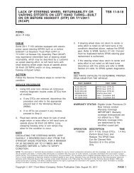
slosh. If the monitor aborts, it will attempt to run again (up to 20 or more times) until the maximum time-after-startis reached.Phase 3 - Vacuum releaseThe vapor generation check is initiated by opening the Canister Vent Solenoid <strong>for</strong> a fixed period of time andreleasing any vacuum. The VMV remains closed.Phase 4 - Vapor generationIn this phase, the sealed system is monitored to determine if tank pressure remains low or if it is rising due toexcessive vapor generation The initial tank pressure is recorded. The pressure is monitored <strong>for</strong> a change fromthe initial pressure, and <strong>for</strong> absolute pressure. If the pressure rise due to vapor generation is below the thresholdlimit <strong>for</strong> absolute pressure and <strong>for</strong> the change in pressure, and a 0.040” dia leak was indicated in phase 2, aP0442 DTC is stored. If the pressure rise due to vapor generation is below the threshold limit <strong>for</strong> absolutepressure and <strong>for</strong> the change in pressure, and a 0.020” dia leak was indicated in phase 2, a 0.020” idle check flagis set to run the 0.020” leak check during idle conditions.Idle CheckThe long test times required to detect a 0.020” dia leak in combination with typical road grades can lead to false0.020” leak indications while the vehicle is in motion. The Idle Check repeats Phases 0 and 2 with the vehiclestationary to screen out leak indications caused by changes in altitude. The 0.020” idle check is done under coldstartconditions to ensure that the fuel is cool and cannot pick up much heat from the engine, fuel rail, or fuelpump. This minimizes vapor generation. The 0.020” idle check is, there<strong>for</strong>e, conducted only during the first 10minutes after engine start.The 0.020” dia leak test entry conditions, test times and thresholds are used. Unique criteria <strong>for</strong> excessivechanges in load, fuel tank pressure and fuel level are used to indicate fuel slosh. The test is aborted if vehiclespeed exceeds a calibrated threshold, approx. 10 mph. The initial vacuum pull-down (phase 0) can start with thevehicle in motion in order to minimize the required time at idle to complete the test. If the vacuum bleed-up isgreater than the 0.020” dia max. criteria during a single monitoring event, a P0456 DTC is stored. If the vacuumbleed-up is less than the 0.020” dia min. criteria, the pending P0456 DTC may be cleared. If the vacuum bleed-upis in between, no leak assessment is made. A flowchart of the entire 0.020” test sequence is provided below, on asubsequent page.Ford’s 0.020” evaporative system monitor is designed to run during extended, cold-start idle conditions where thefuel is cool and not likely to generate excessive vapors. These conditions will typically occur at traffic lights orimmediately after start-up, (e.g. idle in the driveway).As indicated previously, the 0.020” idle test uses two sets of malfunction thresholds to screen out test results inthe area where “leak” and “no-leak” distributions overlap. Loss of vacuum greater than the 0.020” malfunctioncriteria is designated as a failure. No/low vacuum loss below the pass criteria is designated a pass. Vacuum lossthat is greater than the pass criteria but less that the failure criteria is indeterminate and does not count as a passor a fail.Test results in this overlap area can stem from high volatility fuel at high ambient temperatures. These situationsare not expected to be encountered routinely by customers. There<strong>for</strong>e, this strategy will only temporarily hampermonitor per<strong>for</strong>mance, while effectively preventing false MIL illumination.A more detailed description of the functional characteristics of the Evaporative Monitor is provided in therepresentative calibration submissions to the agency. Additional calibration in<strong>for</strong>mation is contained on file byFord Motor Company and may be obtained via agency request.FORD MOTOR COMPANY REVISION DATE: DECEMBER 19, 2002 PAGE 21 OF 95
noDone this cycle,Return to Start.040" entryconditions met?6 hr soak,40-100F, 15-85%fuelyes.020" entryconditions met?6 hr soak, 40-80F,50-85% fuel, idleflag set?noRun Grossleak cruise test1XGross leak?noyesDone this cycle,Store P0455, P0457,P1443 or P1450pending/MIL code*,Return to StartyesClear refueling flagSet refuelingflagyesRefueling event(>20% fuelchange)?noRefuelingflag set?no.020" run timer(10 min)expired?noyesyesRun .040" cruise test3X, use .040" bleedup &slosh criteriaExtend .040 test timeto per<strong>for</strong>m .020" cruisetest 1X, use .020"bleedup, fuel level &slosh criteriaPass .040"test?yesPass .020test?yesnonoDone this cycle,Store P0442pending/MIL code*,Return to Start"Leak" criteria exceeded,set .020" idle flag,done this cycle.Return to Start"Leak" criteria notexceeded, done this cycle,Return to Start2/11/99StartTry to pulldown tank to-7 " H2O during normaldriving in anticipationof idle test* Note: It takes 2 consecutive failures store a DTC and illuminate the MIL.It takes 3 consecutive passes to turn the MIL off.Run .020 Idle test1X, VSS < 3 mph, use.020" bleedup & sloshcriteriaFord 2000 <strong>MY</strong> 0.020" Dia. Leak Check StrategyPass .020test?yesnoStore P0456 pending/MILcode* if "leak" criteriaexceeded,take no action if inbetween "leak" and"no-leak" limits,done this cycle,Return to StartDone this cycle,Clear .020 Idle flag if lessthan "no-leak" criteria,Erase P0456 pendingcode if set,Return to StartFORD MOTOR COMPANY REVISION DATE: DECEMBER 19, 2002 PAGE 22 OF 95
0.020” EVAP Monitor <strong>Operation</strong>:DTCsMonitor executionMonitor SequenceSensors/Components OKMonitoring DurationP0455 (gross leak),P1450, (excessive vacuum),P0457 (gross leak, cap off),P1443 (gross leak, no flow),P0442 (0.040” leak),P0456 (0.020” leak)once per driving cycle <strong>for</strong> 0.040” dia leakonce per driving cycle, no refueling event <strong>for</strong> 0.020” dia leakHO2S monitor <strong>for</strong> front sensors completed and OKMAF, IAT, VSS, ECT, CKP, TP, FTP, VMV, CVS360 seconds <strong>for</strong> 0.040” (see disablement conditions below)60 seconds <strong>for</strong> 0.020” (see disablement conditions below)Typical 0.020” EVAP monitor entry conditions, Phases 0 through 4:Entry condition Minimum MaximumEngine off (soak) time6 hoursTime since engine start-up <strong>for</strong> 0.040” 330 seconds 1800 secondsTime since engine start-up <strong>for</strong> 0.020” idle test 30 seconds 600 secondsRefueling event (<strong>for</strong> 0.020” idle test only)noneIntake Air Temp <strong>for</strong> 0.040” 40 o F 90 - 100 o FIntake Air Temp <strong>for</strong> 0.020” 40 o F 90 o FVehicle Speed <strong>for</strong> cruise test, 0.040 and 0.020” 40 mph 80 mphVehicle Speed <strong>for</strong> idle test, 0.020”3 mphFuel Fill Level <strong>for</strong> 0.040” 15% 85%Fuel Fill Level <strong>for</strong> 0.020” 40% 85%BARO (
Typical 0.020” EVAP abort (fuel slosh) conditions <strong>for</strong> Phase 2:Change in load: > 20% <strong>for</strong> 0.040”Change in load: > 10% <strong>for</strong> 0.020”Change in tank pressure: > 1 “ H 2 O <strong>for</strong> 0.040”Change in tank pressure: > 1 “ H 2 O <strong>for</strong> 0.020”Change in fuel fill level: > 15% <strong>for</strong> 0.040”Change in fuel fill level: > 8% <strong>for</strong> 0.020”Number of aborts: > 20 (may be up to 255)Typical 0.020 EVAP monitor malfunction thresholds:P1450 (Excessive vacuum): < -8.0 in H 2 O over a 30 second evaluation time or > -4. in H 2 O vapor generation.P0455 (Gross leak): > -8.0 in H 2 O over a 30 second evaluation time.P0457 (Gross leak, cap off): > -8.0 in H 2 O over a 30 second evaluation time after a refueling event.P0442 (0.040” leak): > 2.5 in H 2 O bleed-up over a 15 sec. evaluation time at 75% fuel fill.(Note: bleed-up and evaluation times vary as a function of fuel fill level).P0456 (0.020” leak): > 2.5 in H 2 O bleed-up over a 30 sec. evaluation time at 75% fuel fill.(Note: bleed-up and evaluation times vary as a function of fuel fill level)P0442 vapor generation limit: < 2.5 in H 2 O over a 100 second evaluation time.J1979 Evaporative <strong>System</strong> Mode $06 DataTest ID Comp ID Description <strong>for</strong> J1850 Units$26 $00 Phase 0 Initial tank vacuum and minimum limit in H 2 0$26 $00 Phase 0 Initial tank vacuum and maximum limit in H 2 0$27 $00 Phase 2 0.040” cruise leak check vacuum bleed-up andmaximum 0.040” leak threshold$28 $00 Phase 2 0.020” cruise leak check vacuum bleed-up and maxleak threshold$2A $00 Phase 4 Vapor generation maximum change in pressure andmax threshold$2B $00 Phase 4 Vapor generation maximum absolute pressure rise andmax threshold$2C $00 Phase 2 0.020” idle leak check vacuum bleed-up and maximum“leak” threshold$2D $00 Phase 2 0.020” idle leak check vacuum bleed-up and max “noleak”thresholdin H 2 0in H 2 0in H 2 0in H 2 0in H 2 0in H 2 0Conversion <strong>for</strong> Test IDs $26 through $2D: Take value, subtract 32,768, and then multiply result by 0.00195 toget inches of H20. The result can be positive or negative.Note: Default values (-64 in H 2 0) will be display <strong>for</strong> all the above TIDs if the evap monitor has nevercompleted. If all or some phases of the monitor have completed on the current or last driving cycle, defaultvalues will be displayed <strong>for</strong> any phases that had not completed.FORD MOTOR COMPANY REVISION DATE: DECEMBER 19, 2002 PAGE 24 OF 95
Test ID Comp ID Description <strong>for</strong> J1850 (new <strong>2003</strong> <strong>MY</strong> strategies) Units$61 $00 Phase 0 Initial tank vacuum and minimum vacuum limit (data <strong>for</strong>P1450 – excessive vacuum)$62 $00 Phase 4 Vapor generation minimum change in pressure andminimum vacuum limit (data <strong>for</strong> P1450, VMV stuck open)$63 $00 Phase 0 Initial tank vacuum and gross leak maximum vacuumlimit (data <strong>for</strong> P0455/P0457 – gross leak/cap off)$64 $00 Phase 2 0.040” cruise leak check vacuum bleed-up andmaximum vacuum limit (data <strong>for</strong> P0442 – 0.040" leak)$65 $00 Phase 2 0.020” idle leak check vacuum bleed-up and maximumvacuum limit (data <strong>for</strong> P0456 – 0.020" leak)in H 2 0in H 2 0in H 2 0in H 2 0in H 2 0Conversion <strong>for</strong> Test IDs $61 through $65: Take value, subtract 32,768, and then multiply result by 0.00195 toget inches of H 2 0. The result can be positive or negative.Note: Default values (0.0 in H 2 0) will be displayed <strong>for</strong> all the above TIDs if the evap monitor has nevercompleted. Each TID is associated with a particular DTC. The TID <strong>for</strong> the appropriate DTC will be updatedbased on the current or last driving cycle, default values will be displayed <strong>for</strong> any phases that have notcompleted.Monitor ID Test ID Description <strong>for</strong> CAN (new <strong>2003</strong> <strong>MY</strong> strategies) Units$3A $80 Phase 0 Initial tank vacuum and minimum vacuum limit (data <strong>for</strong>P1450 – excessive vacuum)$3A $81 Phase 4 Vapor generation minimum change in pressure andminimum vacuum limit (data <strong>for</strong> P1450, VMV stuck open)$3A $82 Phase 0 Initial tank vacuum and gross leak maximum vacuumlimit (data <strong>for</strong> P0455/P0457 – gross leak/cap off)$3B $80 Phase 2 0.040” cruise leak check vacuum bleed-up andmaximum vacuum limit (data <strong>for</strong> P0442 – 0.040" leak)$3C $80 Phase 2 0.020” idle leak check vacuum bleed-up and maximumvacuum limit (data <strong>for</strong> P0456 – 0.020" leak)PascalsPascalsPascalsPascalsPascalsNote: Default values (0.0 in H 2 0) will be displayed <strong>for</strong> all the above TIDs if the evap monitor has nevercompleted. Each TID is associated with a particular DTC. The TID <strong>for</strong> the appropriate DTC will be updatedbased on the current or last driving cycle, default values will be displayed <strong>for</strong> any phases that have notcompleted.FORD MOTOR COMPANY REVISION DATE: DECEMBER 19, 2002 PAGE 25 OF 95
Additional malfunctions that are be identified during the evaporative system integrity check are as follows:The Vapor Management Valve (purge solenoid) output circuit is checked <strong>for</strong> opens and shorts (P0443), astuck closed VMV generates a P0455, a leaking or stuck open VMV generates a P1450.The Fuel Tank Pressure Transducer input circuit is checked <strong>for</strong> out of range values (P0452 short, P0453open) as well as noisy readings (P0451 noisy). An open power input circuit or stuck check valve generatesa P1450.Fuel Tank Pressure Sensor Transfer FunctionFTP volts = [ Vref * ( 0.14167 * Tank Pressure) + 2.6250 ] / 5.00Volts A/D Counts in PCM Fuel Tank Pressure, Inches H 2 O0.100 20 -17.820.500 102 -15.01.208 247 -10.02.265 464 03.475. 712 6.04.750 973 15.04.90 1004 16.06The Canister Vent Solenoid output circuit is checked <strong>for</strong> opens and shorts (P1451 or P0446), a stuckclosed CVS generates a P1450, a leaking or stuck open CVS generates a P0455.The Fuel Level Input is checked <strong>for</strong> out of range values (opens/ shorts). The FLI input can be hardwired tothe PCM or be obtained from the serial data link, typically from the instrument cluster. If the FLI signal isopen or shorted, a P0460 is set. Some <strong>2003</strong> <strong>MY</strong> software will be able to discriminate between an openand short and set the appropriate DCT (P0462 circuit low and P0463 circuit high). The FLI signal is alsochecked to determine if it is stuck. If the PCM calculates the amount of fuel being consumed byaccumulating fuel pulsewidth. If the there is an insufficient corresponding change in fuel tank level, aP0460 DTC is set. Finally, the Fuel Level Input is checked <strong>for</strong> noisy readings. If the FLI input changes froman in-range to out-of-range value repeatedly, a P0461 DTC is set.The requirement to clear the I/M readiness bit <strong>for</strong> the evap system monitor after 2 driving cycles was phased instarting in the 1999 <strong>MY</strong>. (See Readiness Code section below.)FORD MOTOR COMPANY REVISION DATE: DECEMBER 19, 2002 PAGE 26 OF 95
EVAP Component Monitor <strong>Operation</strong>:DTCsMonitor executionMonitor SequenceSensors OKMonitoring DurationP0443, P1451 or P0446, P0452, P0453, P0460, P0461, P0462, P0463continuous (5 seconds to identify malfunction or obtain smart driver status)Nonenot applicable5 seconds <strong>for</strong> electrical malfunctionsTypical evap component malfunction thresholds:P0443 (Vapor Management Valve Circuit): open/shorted at 0 and 100% duty cycleP1451 or P0446 (Canister Vent Solenoid Circuit): open/shortedP0452 (Fuel Tank Pressure Sensor Circuit Low): < -17.82 in H 2 OP0453 (Fuel Tank Pressure Sensor Circuit High): > 16.06 in H 2 OP0451 (Fuel Tank Pressure Sensor Circuit Noisy): > 14 in H 2 O change between samples, sampled every 10seconds, more than 100 fault occurrencesP0460 or P0462 (Fuel Level Input Circuit Low): < 5 ohmsP0460 or P0463 (Fuel Level Input Circuit High): > 200 ohmsP0460 (Fuel Level Input Stuck): > 20% difference in calculated fuel tank capacity consumed versus change infuel level input reading)P0461 (Fuel Level Input Noisy): > 100 circuit low or circuit high exceedences, sampled every 0.100 secondsFORD MOTOR COMPANY REVISION DATE: DECEMBER 19, 2002 PAGE 27 OF 95
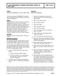
Fuel <strong>System</strong> MonitorAs fuel system components age or otherwise change over the life of the vehicle, the adaptive fuel strategy learnsdeviations from stoichiometry while running in closed loop fuel. These learned corrections are stored in KeepAlive Memory as long term fuel trim corrections. They may be stored into an 8x10 rpm/load table or they may bestored as a function of air mass. As components continue to change beyond normal limits or if a malfunctionoccurs, the long-term fuel trim values will reach a calibratable rich or lean limit where the adaptive fuel strategy isno longer allowed to compensate <strong>for</strong> additional fuel system changes. Long term fuel trim corrections at their limits,in conjunction with a calibratable deviation in short term fuel trim, indicate a rich or lean fuel system malfunction.Note that in the PCM, both long and short-term fuel trim are multipliers in the fuel pulse width equation. Scan toolsnormally display fuel trim as percent adders. If there were no correction required, a scan tool would display 0%even though the PCM was actually using a multiplier of 1.0 in the fuel pulse width equation.Fuel Mass = Air Mass * Long-term Fuel TrimShort-term Fuel Trim * 14.64Lean FaultLong-term correction limit1.25V_KAMBAR_MAXV_LAMBAR_MAXKAM_BARn/LAM_BARn1.000.75XLean Fault SetP0171 or P0174V_LAMBAR_MINV_KAMBAR_MINFuel Mass Req = … KAMREF ...LAMBSESECONDSLAM_BARnKAM_BARn1.25Rich FaultShort-term correction limitRich Fault SetP0172 or P0175XV_KAMBAR_MAXV_LAMBAR_MAXKAM_BARn/LAM_BARn1.00Long-term correction limitV_LAMBAR_MIN0.75V_KAMBAR_MINFuel Mass Req = … KAMREF ...LAMBSESECONDSLAM_BARnKAM_BARnFORD MOTOR COMPANY REVISION DATE: DECEMBER 19, 2002 PAGE 28 OF 95
Fuel Monitor <strong>Operation</strong>:DTCsMonitor executionMonitor SequenceSensors OKMonitoring DurationP0171 Bank 1 Lean, P0174 Bank 2 LeanP0172 Bank 1 Rich, P0175 Bank 2 Richcontinuous while in closed loop fuelnoneFuel Rail Pressure (if available)2 seconds to register malfunctionTypical fuel monitor entry conditions:Entry condition Minimum MaximumRPM Range idle 4,000 rpmAir Mass Range0.75 lb/minPurge Dutycycle 0% 0%Typical fuel monitor malfunction thresholds:Long Term Fuel Trim correction cell currently being utilized in conjunction with Short Term Fuel Trim:Lean malfunction: LONGFT > 25%, SHRTFT > 5%Rich malfunction: LONGFT < 25%, SHRTFT < 10%FORD MOTOR COMPANY REVISION DATE: DECEMBER 19, 2002 PAGE 29 OF 95
HO2S MonitorFront HO2S SignalThe time between HO2S switches is monitored after vehicle startup and during closed loop fuel conditions.Excessive time between switches or no switches since startup indicate a malfunction. Since “lack of switching”malfunctions can be caused by HO2S sensor malfunctions or by shifts in the fuel system, DTCs are stored thatprovide additional in<strong>for</strong>mation <strong>for</strong> the “lack of switching” malfunction. Different DTCs indicate whether the sensorwas always indicates lean/disconnected (P1131 or P2195, P1151 or P2197), or always indicates rich (P1132 orP2196, P1152 or P2198).<strong>2003</strong> <strong>MY</strong> vehicles will monitor the HO2S signal <strong>for</strong> high voltage, in excess of 1.5 volts and store a unique DTC.(P0132, P0152). An over voltage condition is caused by a HO2S heater or battery power short to the HO2S signalline.HO2S “Lack of Switching” <strong>Operation</strong>:DTCs P1131 or P2195 - Lack of switching, sensor indicates lean, Bank 1P1132 or P2196 - Lack of switching, sensor indicates rich, Bank 1P0132 Over voltage, Bank 1P1151 or P2197 - Lack of switching, sensor indicates lean, Bank 2P1152 or P2198 - Lack of switching, sensor indicates rich, Bank 2P0152 Over voltage, Bank 2Monitor executionMonitor SequenceSensors OKMonitoring Durationcontinuous, from startup and while in closed loop fuelNoneTP, MAF, ECT, IAT, FTP30 to 60 seconds to register a malfunctionTypical HO2S “Lack of Switching” entry conditions:Entry condition Minimum MaximumClosed Loop RequestedEngine Load 20% 60%Time since engine start-upInferred Exhaust Temperature180 seconds800 o FTypical HO2S “Lack of Switching” malfunction thresholds:< 5 switches since startup after 30 seconds in test conditions> 60 seconds since last switch while closed loopFORD MOTOR COMPANY REVISION DATE: DECEMBER 19, 2002 PAGE 30 OF 95
The HO2S is also tested functionally. The response rate is evaluated by entering a special 1.5 Hz. square wave,fuel control routine. This routine drives the air/fuel ratio around stoichiometry at a calibratable frequency andmagnitude, producing predictable oxygen sensor signal amplitude. A slow sensor will show reduced amplitude.Oxygen sensor signal amplitude below a minimum threshold indicates a slow sensor malfunction. (P0133 Bank 1,,P0153 Bank 2). If the calibrated frequency was not obtained while running the test because of excessive purgevapors, etc., the test will be run again until the correct frequency is obtained.HO2S Response Rate <strong>Operation</strong>:DTCs P0133 (slow response Bank 1)P0153 (slow response Bank 2)Monitor executiononce per driving cycleMonitor SequenceNoneSensors OKECT, IAT, MAF, VSS, CKP, TP, CMP, no misfire DTCs, FRPMonitoring Duration4 secondsTypical HO2S response rate entry conditions:Entry condition Minimum MaximumShort Term Fuel Trim Range 70% 130%Engine Coolant Temp 150 o F 240 o FIntake Air Temp140 o FEngine Load 20% 50%Vehicle Speed 30 mph 60 mphEngine RPM 1000 rpm 2000 rpmTime since entering closed loop fuel10 secondsTypical HO2Sresponse rate malfunction thresholds:Voltage amplitude: < 0.5 voltsJ1979 Front HO2S Mode $06 DataTest ID Comp ID Description <strong>for</strong> J1850 Units$01 $11 HO2S11 voltage amplitude and voltage threshold Volts$01 $21 HO2S21 voltage amplitude and voltage threshold Volts$03 $01 Upstream O2 sensor switch-point voltage VoltsMonitor ID Test ID Description <strong>for</strong> CAN$01 $80 HO2S11 voltage amplitude and voltage threshold Volts$01 $01 H02S11 sensor switch-point voltage Volts$05 $80 HO2S21 voltage amplitude and voltage threshold Volts$05 $01 H02S21 sensor switch-point voltage VoltsConversion <strong>for</strong> Test IDs $01 through $03: multiply by 0.00098 to get voltsFORD MOTOR COMPANY REVISION DATE: DECEMBER 19, 2002 PAGE 31 OF 95
Rear HO2S SignalA functional test of the rear HO2S sensors is done during normal vehicle operation. The peak rich and leanvoltages are continuously monitored. Voltages that exceed the calibratable rich and lean thresholds indicate afunctional sensor. If the voltages have not exceeded the thresholds after a long period of vehicle operation, theair/fuel ratio may be <strong>for</strong>ced rich or lean in an attempt to get the rear sensor to switch. This situation normally occursonly with a green catalyst (< 500 miles). If the sensor does not exceed the rich and lean peak thresholds, amalfunction is indicated.<strong>2003</strong> <strong>MY</strong> vehicles will monitor the rear HO2S signal <strong>for</strong> high voltage, in excess of 1.5 volts and store a uniqueDTC. (P0138, P0158). An over voltage condition is caused by a HO2S heater or battery power short to the HO2Ssignal line.Some <strong>2003</strong> Partial Zero Emission Vehicles (PZEV) will utilize three sets of HO2S sensors. The front sensors(HO2S11/HO2S21) are the primary fuel control sensors. The next sensors downstream in the exhaust are utilizedto monitor the light-off catalyst (HO2S12/HO2S22). The last sensors downstream in the exhaust(HO2S13/Ho2S23) are utilized <strong>for</strong> very long term fuel trim in order to optimize catalyst efficiency (Fore Aft OxygenSensor Control). Ford's first PZEV vehicle uses a 4-cylinder engine so only the Bank 1 DTCs are utilized.Rear HO2S Check <strong>Operation</strong>:DTCs Sensor 2P0136 HO2S12 No activity orP2270 HO2S12 Signal Stuck LeanP2271 HO2S12 Signal Stuck RichP0138 HO2S12 Over voltageP0156 HO2S22 No activity orP2272 HO2S22 Signal Stuck LeanP2273 HO2S22 Signal Stuck RichP0158 HO2S22 Over voltageDTCs Sensor 3Monitor executionMonitor SequenceSensors OKMonitoring DurationP2274 HO2S13 Signal Stuck LeanP2275 HO2S13 Signal Stuck RichP0144 HO2S13 Over voltageP2276 HO2S23 Signal Stuck LeanP2277 HO2S23 Signal Stuck RichP0164 HO2S23 Over voltageonce per driving cycle <strong>for</strong> activity test, continuous <strong>for</strong> over voltage testnonecontinuous until monitor completedFORD MOTOR COMPANY REVISION DATE: DECEMBER 19, 2002 PAGE 32 OF 95
Typical Rear HO2S check entry conditions:Entry condition Minimum MaximumInferred exhaust temperature range 400 o F 1400 o FRear HO2S heater-on timeThrottle position120 secondsPart throttleEngine RPM (<strong>for</strong>ced excursion only) 1000 rpm 2000 rpmTypical Rear HO2S check malfunction thresholds:Does not exceed rich and lean threshold envelope:Rich < 0.25 to 0.50 voltsLean > 0.40 to 0.65 voltsJ1979 Rear HO2S Mode $06 DataTest ID Comp ID Description <strong>for</strong> J1850 Units$03 $02 Downstream O2 sensor switch-point voltage voltsConversion <strong>for</strong> Test ID $03: multiply by 0.00098 to get voltsMonitor ID Test ID Description <strong>for</strong> CAN$02 $01 HO2S12 sensor switch-point voltage volts$06 $01 HO2S22 sensor switch-point voltage volts$03 $01 HO2S13 sensor switch-point voltage volts$07 $01 HO2S23 sensor switch-point voltage voltsFORD MOTOR COMPANY REVISION DATE: DECEMBER 19, 2002 PAGE 33 OF 95
HO2S Heaters, front and rearThe HO2S heaters are monitored <strong>for</strong> proper voltage and current. A HO2S heater voltage fault is determined byturning the heater on and off and looking <strong>for</strong> corresponding voltage change in the heater output driver circuit in thePCM.A separate current-monitoring circuit monitors heater current once per driving cycle. The heater current is actuallysampled three times. If the current value <strong>for</strong> two of the three samples falls below a calibratable threshold, theheater is assumed to be degraded or malfunctioning. (Multiple samples are taken <strong>for</strong> protection against noise onthe heater current circuit.)HO2S Heater Monitor <strong>Operation</strong>:DTCs Sensor 1 - P0135 Bank 1, P0155 Bank 2Sensor 2 - P0141 Bank 1, P0161 Bank2Sensor 3 – P0055 Bank 1, P0061 Bank 2Monitor executionMonitor SequenceSensors OKMonitoring Durationonce per driving cycle <strong>for</strong> heater current, continuous <strong>for</strong> voltage monitoringheater voltage check is done prior to heater current check< 5 secondsTypical HO2S heater monitor entry conditions:Entry condition Minimum MaximumInferred exhaust temperature range 250 o F 1400 o FHO2S heater-on time120 secondsTypical HO2S heater check malfunction thresholds:Smart driver status indicated malfunctionHeater current outside limits: < 0.220 amps or > 3 amps, (NTK)< 0.400 amps or > 3 amps, (Bosch)< 0.465 amps or > 3 amps, (NTK Fast Light Off)< 0.230 amps or > 3 amps, (Bosch Fast Light Off)FORD MOTOR COMPANY REVISION DATE: DECEMBER 19, 2002 PAGE 34 OF 95
J1979 HO2S Heater Mode $06 DataTest ID Comp ID Description <strong>for</strong> J1850 Units$04 $11 Maximum HO2S11 Heater Current Amps$04 $11 Minimum HO2S11 Heater Current Amps$04 $21 Maximum HO2S21 Heater Current Amps$04 $21 Minimum HO2S21 Heater Current Amps$04 $12 Maximum HO2S12 Heater Current Amps$04 $12 Minimum HO2S12 Heater Current Amps$04 $22 Maximum HO2S22 Heater Current Amps$04 $22 Minimum HO2S22 Heater Current AmpsConversion <strong>for</strong> Test IDs $04: multiply by 0.003906 to get ampsMonitor ID Test ID Description <strong>for</strong> CAN Units$01 $81 HO2S11 Heater Current Amps$05 $81 HO2S21 Heater Current Amps$02 $81 HO2S12 Heater Current Amps$06 $81 HO2S22 Heater Current Amps$03 $81 HO2S13 Heater Current Amps$07 $81 HO2S23 Heater Current AmpsFORD MOTOR COMPANY REVISION DATE: DECEMBER 19, 2002 PAGE 35 OF 95
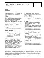
DPFE EGR <strong>System</strong> MonitorThe Delta Pressure Feedback EGR system is a closed loop EGR control system that uses Delta PressureFeedback EGR sensor (DPFE) to measure EGR flow across an orifice in the EGR tube. When the EGR valve isopen, a pressure differential is created across the orifice and measured by the DPFE sensor. This DPFEmeasurement is used to control the EGR vacuum regulator (EVR), which provides vacuum to open and modulatethe EGR valve itself.PCMCONVENTIONALDPFE EGR SYSTEMFRESH AIR INLETEVREGRVALVEINTAKEDPFESENSORDOWNSTREAM (P2)UPSTREAM (P1)FLOW CONTROLORIFICEEXHAUSTDELTA P = P1 - P2FORD MOTOR COMPANY REVISION DATE: DECEMBER 19, 2002 PAGE 36 OF 95
The Delta Pressure Feedback EGR Monitor is a series of electrical tests and functional tests that monitor variousaspects of EGR system operation.First, the Delta Pressure Feedback EGR (DPFE) sensor input circuit is checked <strong>for</strong> out of range values (P1400 orP0405, P1401 or P0406). The Electronic Vacuum Regulator (EVR) output circuit is checked <strong>for</strong> opens and shorts(P1409 or P0403).DPFE EGR Electrical Check <strong>Operation</strong>:DTCsMonitor executionMonitor SequenceSensors OKMonitoring DurationP1400 or P0405 - DPFE Circuit LowP1401 or P0406 - DPFE Circuit HighP1409 or P0403 - EVR circuit open or shortedContinuous, during EGR monitorNone4 seconds to register a malfunctionTypical DPFE EGR electrical check entry conditions:EGR system enabledTypical DPFE EGR electrical check malfunction thresholds:DPFE sensor outside voltage: > 4.96 volts, < 0.0489 voltsEVR solenoid smart driver status indicates open/shortThe DPFE sensor is a ceramic, capacitive-type pressure transducer that monitors the differential pressure across ametering orifice located in the orifice tube assembly. The differential pressure feedback sensor receives this signalthrough two hoses referred to as the downstream pressure hose (REF SIGNAL) and upstream pressure hose (HISIGNAL). The HI and REF hose connections are marked on the aluminum DPFE sensor housing <strong>for</strong> identification(note that the HI signal uses a larger diameter hose). There are two styles of DPFE sensors. The newer, plastichousing utilizes a 1.0-volt offset (zero reading) whereas the older, aluminum housing utilizes either a 0.5-volt or1.0-volt offset. See the ESM EGR section <strong>for</strong> the 0.5-volt offset transfer function. The slopes <strong>for</strong> either offset areidentical.DPFE Sensor Transfer FunctionDPFE volts = Vref [( 0.683 * Delta Pressure) + 20 ] / 100Volts A/D Counts in PCM Delta Pressure, Inches H 2 O0.0489 10 -27.90.76 156 -7.01.0 204 01.24 254 7.02.02 415 303.05 624 604.07 834 904.96 1015 116Note: EGR normally has large amounts of water vapor that are the result of the engine combustion process. Duringcold ambient temperatures, under some circumstances, water vapor can freeze in the DPFE sensor, hoses, aswell as other components in the EGR system. In order to prevent MIL illumination <strong>for</strong> temporary freezing, thefollowing logic is used:FORD MOTOR COMPANY REVISION DATE: DECEMBER 19, 2002 PAGE 37 OF 95
If an EGR system malfunction is detected above 32 o F, the EGR system and the EGR monitor is disabled <strong>for</strong> thecurrent driving cycle. A DTC is stored and the MIL is illuminated if the malfunction has been detected on twoconsecutive driving cycles.If an EGR system malfunction is detected below 32 o F, only the EGR system is disabled <strong>for</strong> the current drivingcycle. A DTC is not stored and the I/M readiness status <strong>for</strong> the EGR monitor will not change. The EGR monitor,however, will continue to operate. If the EGR monitor determined that the malfunction is no longer present (i.e., theice melts), the EGR system will be enabled and normal system operation will be restored.The differential pressure indicated by the DPFE sensor is also checked at idle with zero requested EGR flow toper<strong>for</strong>m the high flow check. If the differential pressure exceeds a calibratable limit, it indicates a stuck open EGRvalve or debris temporarily lodged under the EGR valve seat (P0402).DPFE EGR Stuck open Check <strong>Operation</strong>:DTCsMonitor executionMonitor SequenceSensors OKMonitoring DurationP0402once per driving cycleDone after electrical testsCPS, ECT, IAT, MAF, TP10 seconds to register a malfunctionTypical DPFE EGR stuck open check entry conditions:Entry Condition Minimum MaximumEVR dutycycle (EGR commanded off) 0% 0%Engine RPM (after EGR enabled) at idle IdleTypical DPFE EGR stuck open check malfunction thresholds:DPFE sensor voltage at idle versus engine-off signal: > 0.6 voltsJ1979 DPFE EGR Stuck Open Mode $06 DataTest ID Comp ID Description <strong>for</strong> J1850 Units$45 $20 Delta pressure <strong>for</strong> stuck open test and threshold voltsConversion <strong>for</strong> Test ID $45: Multiply by 0.0156 to get A/D counts (0-1024) or 0.0000763 to get voltageMonitor ID Test ID Description <strong>for</strong> CAN Conventional DPFE Units$31 $84 Delta pressure <strong>for</strong> stuck open test and threshold kPaFORD MOTOR COMPANY REVISION DATE: DECEMBER 19, 2002 PAGE 38 OF 95
On conventional Delta PFE systems, after the vehicle is started, during vehicle acceleration, the differentialpressure indicated by the DPFE sensor at zero EGR flow is checked to ensure that both hoses to the DPFEsensor are connected. Under this condition, the differential pressure should be zero. If the differential pressureindicated by the DPFE sensor exceeds a maximum positive threshold, a downstream DPFE hose malfunction isindicated (P1406). If the differential pressure falls below a minimum negative threshold, an upstream DPFE hosemalfunction is indicated (P1405).DPFE EGR Hose Check <strong>Operation</strong>:DTCsMonitor executionMonitor SequenceSensors OKMonitoring DurationP1405 - Upstream Hose Off or PluggedP1406 – Downstream Hose Off or Pluggedonce per driving cycleAfter P0402 test completedMAF4 seconds to register a malfunctionTypical DPFE EGR hose check entry conditions:Entry Condition Minimum MaximumEVR dutycycle (EGR commanded off) 0% 0%Mass Air FlowInferred exhaust backpressure13 in H 2 O8 lb/minTypical DPFE EGR hose check malfunction thresholds:DPFE sensor voltage: < 7 in H 2 O, > 7 in H 2 OJ1979 DPFE EGR Hose Check Mode $06 DataTest ID Comp ID Description <strong>for</strong> J1850 Units$42 $11 Delta pressure <strong>for</strong> upstream hose test and threshold in. H 2 0$42 $12 Delta pressure <strong>for</strong> downstream hose test and threshold in. H 2 0Conversion <strong>for</strong> Test ID $42: Take value, subtract 32,768, and then multiply result by 0.0078 to get inches ofH 2 0. The result can be positive or negative.Monitor ID Test ID Description <strong>for</strong> CAN Conventional DPFE$31 $80 Delta pressure <strong>for</strong> upstream hose test and threshold kPa$31 $81 Delta pressure <strong>for</strong> downstream hose test and threshold kPaFORD MOTOR COMPANY REVISION DATE: DECEMBER 19, 2002 PAGE 39 OF 95
After the vehicle has warmed up and normal EGR rates are being commanded by the PCM, the low flow check isper<strong>for</strong>med. Since the EGR system is a closed loop system, the EGR system will deliver the requested EGR flow aslong as it has the capacity to do so. If the EVR duty cycle is very high (greater than 80% duty cycle), the differentialpressure indicated by the DPFE sensor is evaluated to determine the amount of EGR system restriction. If thedifferential pressure is below a calibratable threshold, a low flow malfunction in indicated (P0401).EGR Flow Check <strong>Operation</strong>:DTCsMonitor executionMonitor SequenceSensors OKMonitoring DurationP0401 – Insufficient Flowonce per driving cycleDone after hose tests <strong>for</strong> conventional DPFE, after P0402 <strong>for</strong> ESMCPS, ECT, IAT, MAF, TP70 seconds to register a malfunctionTypical EGR flow check entry conditions:Entry Condition Minimum MaximumEVR Dutycycle 80% 100%Engine RPM2500 rpmMass Air Flow Rate of Change6% program loopInferred manifold vacuum 6 in Hg 10 in HgTypical EGR flow check malfunction thresholds:DPFE sensor voltage: < 6 in H 2 OJ1979 EGR Flow Check Mode $06 DataTest ID Comp ID Description <strong>for</strong> J1850 Units$49 $30 Delta pressure <strong>for</strong> flow test and threshold in. H 2 0$4B $30 EVR dutycycle <strong>for</strong> flow test and threshold percentConversion <strong>for</strong> Test ID $4B: multiply by 0.0000305 to get percent dutycycle.Conversion <strong>for</strong> Test ID $49: Take value, subtract 32,768, then multiply result by 0.0078 to get inches of H 2 0.The result can be positive or negative.Monitor ID Test ID Description <strong>for</strong> CAN Conventional DPFE Units$31 $85 Delta pressure <strong>for</strong> flow test and threshold kPaFORD MOTOR COMPANY REVISION DATE: DECEMBER 19, 2002 PAGE 40 OF 95
I/M Readiness IndicationIf the inferred ambient temperature is less than 32 o F, or greater than 140 o F, or the altitude is greater than 8,000feet (BARO < 22.5 "Hg), the EGR monitor cannot be run reliably. In these conditions, a timer starts to accumulatethe time in these conditions. If the vehicle leaves these extreme conditions, the timer starts decrementing, and, ifconditions permit, will attempt to complete the EGR flow monitor. If the timer reaches 500 seconds, the EGRmonitor is disabled <strong>for</strong> the remainder of the current driving cycle and the EGR Monitor I/M Readiness bit will be setto a “ready” condition after one such driving cycle. Starting in the 2002 <strong>MY</strong>, vehicles will require two such drivingcycles <strong>for</strong> the EGR Monitor I/M Readiness bit to be set to a "ready" condition.Note: A few 2001 and 2002 <strong>MY</strong> vehicles do have the above-described bypass logic. If an EGR malfunction isdetected below 32 o F, and the EGR system/monitor has been disabled, the EGR Monitor I/M Readiness bit willretain its current status (possibly "not ready" if DTCs had been recently erased).FORD MOTOR COMPANY REVISION DATE: DECEMBER 19, 2002 PAGE 41 OF 95
ESM DPFE EGR <strong>System</strong> MonitorIn the 2002.5 <strong>MY</strong>, Ford will introduce a revised DPFE system. It functions in the same manner as theconventional DPFE system, however, the various system components have been combined into a singlecomponent called the EGR <strong>System</strong> Module (ESM). This arrangement increases system reliability while reducingcost. By relocating the EGR orifice from the exhaust to the intake, the downstream pressure signal measuresManifold Absolute Pressure (MAP). The ESM will provide the PCM with a differential DPFE signal, identical to theconventional DPFE system. The DPFE signal is obtained by electrically subtracting the MAP and P1 presuresignals and providing this signal to the DPFE input on the PCM. <strong>2003</strong> <strong>MY</strong> and later implementation of the ESMsystem will add a separate input to the PCM <strong>for</strong> the MAP sensor signal.PCMNew ESMDPFE EGR SYSTEMEGR <strong>System</strong> Module(ESM) ComponentsDPFEsignalEVRMAP SIGNALEGRVALVEFRESH AIR INLETVREFSig RtnEGR DCP1INTAKE(MAP)MAPDPFESENSORDELTA P = P1 - MAPEXHAUSTFORD MOTOR COMPANY REVISION DATE: DECEMBER 19, 2002 PAGE 42 OF 95
The ESM Delta Pressure Feedback EGR Monitor is a series of electrical tests and functional tests that monitorvarious aspects of EGR system operation.First, the Delta Pressure Feedback EGR (DPFE) sensor input circuit is checked <strong>for</strong> out of range values (P1400 orP0405, P1401 or P0406). The Electronic Vacuum Regulator (EVR) output circuit is checked <strong>for</strong> opens and shorts(P1409 or P0403).EGR Electrical Check <strong>Operation</strong>:DTCsMonitor executionMonitor SequenceSensors OKMonitoring DurationP1400 or P0405 - DPFE Circuit LowP1401 or P0406 - DPFE Circuit HighP1409 or P0403 - EVR circuit open or shortedContinuous, during EGR monitorNone4 seconds to register a malfunctionTypical EGR electrical check entry conditions:EGR system enabledTypical EGR electrical check malfunction thresholds:DPFE sensor outside voltage: > 4.96 volts, < 0.0489 voltsEVR solenoid smart driver status indicates open/shortDPFE Sensor Transfer FunctionESM DPFE volts = Vref [( 0.683 * Delta Pressure) + 10 ] / 100Volts A/D Counts in PCM Delta Pressure, Inches H 2 O0.0489 10 -13.20.26 156 -7.00.5 204 00.74 254 7.01.52 415 302.55 624 603.57 834 904.96 1015 130.7Note: EGR normally has large amounts of water vapor that are the result of the engine combustion process. Duringcold ambient temperatures, under some circumstances, water vapor can freeze in the DPFE sensor, hoses, aswell as other components in the EGR system. In order to prevent MIL illumination <strong>for</strong> temporary freezing, thefollowing logic is used:If an EGR system malfunction is detected above 32 o F, the EGR system and the EGR monitor is disabled <strong>for</strong> thecurrent driving cycle. A DTC is stored and the MIL is illuminated if the malfunction has been detected on twoconsecutive driving cycles.If an EGR system malfunction is detected below 32 o F, only the EGR system is disabled <strong>for</strong> the current drivingcycle. A DTC is not stored and the I/M readiness status <strong>for</strong> the EGR monitor will not change. The EGR monitor,however, will continue to operate. If the EGR monitor determined that the malfunction is no longer present (i.e., theice melts), the EGR system will be enabled and normal system operation will be restored.FORD MOTOR COMPANY REVISION DATE: DECEMBER 19, 2002 PAGE 43 OF 95
The ESM may provide the PCM with a separate, analog Manifold Absolute Pressure Sensor (MAP) signal. For the<strong>2003</strong> <strong>MY</strong>, the MAP signal has limited use within the PCM. It may be used to read BARO (key on, updated at highload conditions while driving) or to modify requested EGR rates. Note that is the MAP pressure-sensing elementfails in the ESM fails, the DPFE signal is also affected. There<strong>for</strong>e, this MAP test is only checking the circuit from theMAP sensing element to the PCM.The MAP sensor is checked <strong>for</strong> opens, shorts, or out-of-range values by monitoring the analog-to-digital (A/D)input voltage.MAP Sensor Check <strong>Operation</strong>DTCsMonitor executionMonitor SequenceSensors OKMonitoring DurationP0107 (low voltage), P0108 (high voltage)continuousNonenot applicable5 seconds to register a malfunctionMAP electrical check entry conditions:Battery voltage > 11.0 voltsTypical MAP sensor check malfunction thresholds:Voltage < 0.024 volts or voltage > 4.96 voltsFORD MOTOR COMPANY REVISION DATE: DECEMBER 19, 2002 PAGE 44 OF 95
On ESM DPFE systems, after the vehicle is started, the differential pressure indicated by the ESM DPFE sensor atidle, at zero EGR flow is checked to ensure that both hoses to the ESM DPFE sensor are connected. At idle, thedifferential pressure should be zero (both hoses see manifold pressure). If the differential pressure indicated by theESM DPFE sensor exceeds a maximum threshold or falls below a minimum threshold, an upstream ordownstream hose malfunction is indicated (P1405, P1406).ESM DPFE EGR Hose Check <strong>Operation</strong>:DTCsMonitor executionMonitor SequenceSensors OKMonitoring DurationP1405 - Upstream Hose Off or PluggedP1406 – Downstream Hose Off or Pluggedonce per driving cycleafter electrical checks completedMAF10 seconds to register a malfunctionTypical ESM DPFE EGR hose check entry conditions:Entry Conditions Minimum MaximumEVR dutycycle (EGR commanded off) 0% 0%Closed throttle (warm engine idle)Engine Coolant Temperature 150 o F 220 o FTypical ESM EGR hose check malfunction thresholds:DPFE sensor voltage: < -0.122 volts (-11.06 in H 2 O), > 4.69 volts (122.82 in H 2 O)J1979 Mode $06 DataTest ID Comp ID Description <strong>for</strong> J1850 Units$43 $11 Delta pressure sensor voltage <strong>for</strong> upstream hose test and threshold volts$43 $12 Delta pressure sensor voltage <strong>for</strong> downstream hose test and threshold voltsConversion <strong>for</strong> Test ID $45: Multiply by 0.0156 to get A/D counts (0-1024) or 0.0000763 to get voltageMonitor ID Test ID Description <strong>for</strong> CAN ESM DPFE$32 $82 Delta pressure <strong>for</strong> upstream hose test and threshold kPa$32 $83 Delta pressure <strong>for</strong> downstream hose test and threshold kPaFORD MOTOR COMPANY REVISION DATE: DECEMBER 19, 2002 PAGE 45 OF 95
Next, the differential pressure indicated by the DPFE sensor is also checked at idle with zero requested EGR flowto per<strong>for</strong>m the high flow check. If the differential pressure exceeds a calibratable limit, it indicates a stuck openEGR valve or debris temporarily lodged under the EGR valve seat (P0402).EGR Stuck open Check <strong>Operation</strong>:DTCsMonitor executionMonitor SequenceSensors OKMonitoring DurationP0402once per driving cycledone after hose tests completedCPS, ECT, IAT, MAF, TP10 seconds to register a malfunctionTypical EGR stuck open check entry conditions:Entry Condition Minimum MaximumEVR dutycycle (EGR commanded off) 0% 0%Engine RPM (after EGR enabled) at idle IdleTypical EGR stuck open check malfunction thresholds:DPFE sensor voltage at idle versus engine-off signal: > 0.6 voltsJ1979 Mode $06 DataTest ID Comp ID Description <strong>for</strong> J1850 Units$45 $20 Delta pressure <strong>for</strong> stuck open test and threshold voltsConversion <strong>for</strong> Test ID $45: Multiply by 0.0156 to get A/D counts (0-1024) or 0.0000763 to get voltageMonitor ID Test ID Description <strong>for</strong> CAN ESM DPFE Units$32 $84 Delta pressure <strong>for</strong> stuck open test and threshold kPaFORD MOTOR COMPANY REVISION DATE: DECEMBER 19, 2002 PAGE 46 OF 95
After the vehicle has warmed up and normal EGR rates are being commanded by the PCM, the low flow check isper<strong>for</strong>med. Since the EGR system is a closed loop system, the EGR system will deliver the requested EGR flow aslong as it has the capacity to do so. If the EVR duty cycle is very high (greater than 80% duty cycle), the differentialpressure indicated by the DPFE sensor is evaluated to determine the amount of EGR system restriction. If thedifferential pressure is below a calibratable threshold, a low flow malfunction in indicated (P0401).EGR Flow Check <strong>Operation</strong>:DTCsMonitor executionMonitor SequenceSensors OKMonitoring DurationP0401 – Insufficient Flowonce per driving cycledone after P0402 completedCPS, ECT, IAT, MAF, TP70 seconds to register a malfunctionTypical EGR flow check entry conditions:Entry Condition Minimum MaximumEVR Dutycycle 80% 100%Engine RPM2500 rpmMass Air Flow Rate of Change6% program loopInferred manifold vacuum 6 in Hg 10 in HgTypical EGR flow check malfunction thresholds:DPFE sensor voltage: < 6 in H 2 OJ1979 Mode $06 DataTest ID Comp ID Description <strong>for</strong> J1850 Units$49 $30 Delta pressure <strong>for</strong> flow test and threshold in. H 2 0$4B $30 EVR dutycycle <strong>for</strong> flow test and threshold percentConversion <strong>for</strong> Test ID $4B: multiply by 0.0000305 to get percent dutycycle.Conversion <strong>for</strong> Test ID $49: Take value, subtract 32,768, then multiply result by 0.0078 to get inches of H 2 0.The result can be positive or negative.Monitor ID Test ID Description <strong>for</strong> CAN ESM DPFE Units$32 $85 Delta pressure <strong>for</strong> flow test and threshold kPaFORD MOTOR COMPANY REVISION DATE: DECEMBER 19, 2002 PAGE 47 OF 95
I/M Readiness IndicationIf the inferred ambient temperature is less than 32 o F, or greater than 140 o F, or the altitude is greater than 8,000feet (BARO < 22.5 "Hg), the EGR monitor cannot be run reliably. In these conditions, a timer starts to accumulatethe time in these conditions. If the vehicle leaves these extreme conditions, the timer starts decrementing, and, ifconditions permit, will attempt to complete the EGR flow monitor. If the timer reaches 500 seconds, the EGRmonitor is disabled <strong>for</strong> the remainder of the current driving cycle and the EGR Monitor I/M Readiness bit will be setto a “ready” condition after one such driving cycle. Starting in the 2002 <strong>MY</strong>, vehicles will require two such drivingcycles <strong>for</strong> the EGR Monitor I/M Readiness bit to be set to a "ready" condition.Note: A few 2001 and 2002 <strong>MY</strong> vehicles do have the above-described bypass logic. If an EGR malfunction isdetected below 32 o F, and the EGR system/monitor has been disabled, the EGR Monitor I/M Readiness bit willretain its current status (possibly "not ready" if DTCs had been recently erased).FORD MOTOR COMPANY REVISION DATE: DECEMBER 19, 2002 PAGE 48 OF 95
Stepper Motor EGR <strong>System</strong> MonitorThe Electric Stepper Motor EGR <strong>System</strong> uses an electric stepper motor to directly actuate an EGR valve ratherthan using engine vacuum and a diaphragm on the EGR valve. The EGR valve in controlled by commandingfrom 0 to 52 discreet increments or “steps” to get the EGR valve from a fully closed to fully open position. Theposition of the EGR valve determines the EGR flow. Because there is no EGR valve position feedback,monitoring <strong>for</strong> proper EGR flow requires the addition of a MAP sensor.Stepper Motor EGR <strong>System</strong>PCMFRESH AIR INLETStepper MotorEGR Valve04030400Note: Some configurations may differ slightlyMapSensorIntake ManifoldExhaustGatesFORD MOTOR COMPANY REVISION DATE: DECEMBER 19, 2002 PAGE 49 OF 95
The Stepper Motor EGR Monitor consists of an electrical and functional test that checks the stepper motor andthe EGR system <strong>for</strong> proper flow.The stepper motor electrical test is a continuous check of the four electric stepper motor coils and circuits to thePCM. A malfunction is indicated if an open circuit, short to power, or short to ground has occurred in one or moreof the stepper motor coils <strong>for</strong> a calibrated period of time. If a malfunction has been detected, the EGR system willbe disabled, and additional monitoring will be suspended <strong>for</strong> the remainder of the driving cycle, until the nextengine start-up.EGR Stepper Monitor Electrical Check <strong>Operation</strong>:DTCsMonitor executionMonitor SequenceSensors OKMonitoring DurationP0403continuousnone4 seconds to register a malfunctionStepper motor electrical check entry conditions:Battery voltage > 11.0 voltsTypical EGR electrical check malfunction thresholds:“Smart” Coil Output Driver status indicates open or short to ground, or short to powerEGR flow is monitored using an analog Manifold Absolute Pressure Sensor (MAP). If a malfunction has beendetected in the MAP sensor, the EGR monitor will not per<strong>for</strong>m the EGR flow test.The MAP sensor is checked <strong>for</strong> opens, shorts, or out-of-range values by monitoring the analog-to-digital (A/D)input voltage.MAP Sensor Check <strong>Operation</strong>DTCsMonitor executionMonitor SequenceSensors OKMonitoring DurationP0107 (low voltage), P0108 (high voltage)continuousnonenot applicable5 seconds to register a malfunctionMAP electrical check entry conditions:Battery voltage > 11.0 voltsTypical MAP sensor check malfunction thresholds:Voltage < 0.024 volts or voltage > 4.96 voltsFORD MOTOR COMPANY REVISION DATE: DECEMBER 19, 2002 PAGE 50 OF 95
The MAP sensor is also checked <strong>for</strong> rational values. The value of inferred MAP is checked against the actual valueof MAP at idle, under steady load conditions.MAP Sensor Rationality Check <strong>Operation</strong>DTCsMonitor executionMonitor SequenceSensors OKMonitoring DurationP0106continuousNonenot applicable5 seconds to register a malfunctionTypical MAP Rationality check entry conditions:Entry Conditions Minimum MaximumChange in load 5%Engine rpm 500 rpm 2500 rpmClosed throttleTypical MAP Rationality check malfunction thresholds:Difference between inferred MAP and actual MAP > 12 in HgAfter the vehicle has warmed up and normal EGR rates are being commanded by the PCM, the EGR flow check isper<strong>for</strong>med. The flow test is per<strong>for</strong>med once per drive-cycle when a minimum amount of EGR is requested and theremaining entry conditions required to initiate the test are satisfied. If a malfunction is detected, the EGR system aswell as the EGR monitor is disabled until the next engine start-up.The EGR flow test is done by observing the behavior of two different values of MAP - the analog MAP sensorreading, and inferred MAP, (MAP calculated from the Mass Air Flow Sensor, throttle position, rpm, BARO, etc.).During normal, steady-state operating conditions, EGR is intrusively commanded on to a specified percentage.Then, EGR is commanded off. If the EGR system is working properly, there is a significant difference in both theobserved and the calculated values of MAP, between the EGR-on and the EGR-off states.When the flow test entry condition have been satisfied, EGR is commanded to flow at a calibrated test rate (about10%). At this time, the value of MAP is recorded (EGR-On MAP). The value of inferred MAP EGR-On IMAP is alsorecorded. Next the EGR is commanded off (0%). Again, the value of MAP is recorded (EGR-Off MAP). The valueof EGR-Off IMAP is also recorded. Typically, 7 such On/Off samples are taken. After all the samples have beentaken, the average EGR-On MAP, EGR-On IMAP, EGR-Off MAP and EGR-Off IMAP values are stored.Next, the differences between the EGR-On and EGR-Off values are calculated:MAP-delta = EGR-On MAP - EGR-Off MAPIMAP delta = EGR-On IMAP - EGR-Off IMAP(analog MAP)(inferred MAP)If the sum of MAP-delta and IMAP-delta exceeds a maximum threshold or falls below a minimum threshold, aP0400 high or low flow malfunction is registered.As an additional check, if the EGR-On MAP exceeds a maximum threshold (BARO - a calibrated value), a P0400low flow malfunction is registered. This test detects reduced EGR flow on systems where the MAP pickup point isnot located in the intake manifold, but is located just upstream of the EGR valve, in the EGR delivery tube.FORD MOTOR COMPANY REVISION DATE: DECEMBER 19, 2002 PAGE 51 OF 95
Note: BARO is inferred at engine startup using the KOEO MAP sensor reading. It is updated during high, partthrottle,high rpm engine operation.EGR Flow Check <strong>Operation</strong>:DTCsMonitor executionMonitor SequenceSensors OKMonitoring DurationP0400once per driving cycleNoneCPS, ECT, IAT, MAF, MAP, TP, BARO not available yet15 seconds to register a malfunction (assumes 4 samples)Typical EGR flow check entry conditions:Entry Condition Minimum MaximumDesired EGR Mass Flow> 0 lb/minEngine RPM 1450 rpm 2700 rpmInferred Ambient Air Temperature 20 o F 140 o FEngine Coolant Temperature164 o FRelative Throttle Position 0.09 volts 0.6 voltsEngine Load 42 % 63 %Vehicle Speed 47 mph 56 mphEngine RPM Steady (change/0.050 sec)Throttle Position Steady (change/0.050 sec)50 rpm0.024 voltsEngine Load Steady (change/0.050 sec) 1.5 %BAROO2 sensor tests not running: amplitude test, openloopdownstream <strong>for</strong>ced-excursion testNo accessory state changes:22.5 "HgNeutral/Drive,A/C On/Off,Low Speed Fan On/Off,Power Steering On/Off,High Speed Fan On/OffTypical EGR flow check malfunction thresholds:Sum of MAP-delta and IMAP delta < 0.62 " Hg orSum of MAP-delta and IMAP delta > 8.00 " Hg orEGR-On MAP > BARO – 0FORD MOTOR COMPANY REVISION DATE: DECEMBER 19, 2002 PAGE 52 OF 95
J1979 Mode $06 DataTest ID Comp ID Description <strong>for</strong> J1850 Units$4E $31 Sum of MAP-delta and IMAP delta and max. threshold in Hg$4E $31 Sum of MAP-delta and IMAP delta and min. threshold in Hg$4F $00 EGR-On MAP and max threshold in HgConversion <strong>for</strong> Test ID 4E and 4F: Take value and multiply result by 0.0078125 to get inches of Hg. Theresult is always positive.Monitor ID Test ID Description <strong>for</strong> CAN Units$33 $80 Sum of MAP-delta and IMAP delta, min and max thresholds kPa$33 $81 EGR-On MAP and max threshold kPaI/M Readiness IndicationIf the inferred ambient temperature is less than 20 o F, greater than 130 o F, or the altitude is greater than 8,000 feet(BARO < 22.5 "Hg), the EGR flow test cannot be reliably done. In these conditions, the EGR flow test issuspended and a timer starts to accumulate the time in these conditions. If the vehicle leaves these extremeconditions, the timer starts decrementing, and, if conditions permit, will attempt to complete the EGR flow monitor.If the timer reaches 500 seconds, the EGR flow test is disabled <strong>for</strong> the remainder of the current driving cycle andthe EGR Monitor I/M Readiness bit will be set to a “ready” condition after one such driving cycle. Starting in the2002 <strong>MY</strong>, vehicles will require two such driving cycles <strong>for</strong> the EGR Monitor I/M Readiness bit to be set to a "ready"condition.FORD MOTOR COMPANY REVISION DATE: DECEMBER 19, 2002 PAGE 53 OF 95
PCV <strong>System</strong> MonitorFord plans to comply with the PCV monitoring requirements by modifying the current PCV system design. ThePCV valve will be installed into the rocker cover using a quarter-turn cam-lock design to prevent accidentaldisconnection. High retention <strong>for</strong>ce molded plastic lines will be used from the PCV valve to the intake manifold.The diameter of the lines and the intake manifold entry fitting will be increased so that inadvertent disconnectionof the lines after a vehicle is serviced will cause either an immediate engine stall or will not allow the engine to berestarted. Some vehicles will incorporate such designs beginning in the 2001 <strong>MY</strong>. In the event that the vehicledoes not stall if the line between the intake manifold and PCV valve is inadvertently disconnected, the vehicle willhave a large vacuum leak that will cause the vehicle to run lean at idle. This will illuminate the MIL after twoconsecutive driving cycles and will store one or more of the following codes: Lack of O2 sensor switches, Bank1(P1131 or P2195), Lack of O2 sensor switches Bank 2 (P1151 or P2197), Fuel <strong>System</strong> Lean, Bank1 (P0171),,Fuel <strong>System</strong> Lean, Bank 2 (P0174)Thermostat MonitorFord plans to comply with the thermostat monitoring requirement by using a slightly-modified version of thecurrent “Insufficient temperature <strong>for</strong> closed-loop” test (P0125 or P0128). If the engine is being operated in amanner that is generating sufficient heat, the engine coolant temperature (ECT) or cylinder head temperature(CHT) should warm up in a predictable manner. A timer is incremented while the engine is at moderate load andvehicle speed is above a calibrated limit. The target/minimum timer value is based on ambient air temperature atstart-up. If the timer exceeds the target time and ECT/CHT has not warmed up to the target temperature, amalfunction is indicated. The test runs if the start-up IAT temperature is below the target temperature. A 2-hourengine-off soak time is required to erase a pending or confirmed DTC. This feature prevents false-passes whereengine coolant temperature rises after the engine is turned off during a short engine-off soak. The targettemperature is calibrated to the thermostat regulating temperature minus 20 o F. For a typical 195 o F thermostat,the warm-up temperature would be calibrated to 175 o F. This test is being phased in starting in the 2000 <strong>MY</strong>. Avehicle, which is not part of the thermostat monitor phase-in, utilizes a 140 o F warm-up temperature.Insufficient Temperature <strong>for</strong> Closed Loop Check <strong>Operation</strong>:DTCsMonitor executionMonitor SequenceMonitoring DurationP0125 or P0128Once per driving cycleNone300 to 800 seconds within test entry conditions, based on ambient temperatureTypical P0125/P0128 check entry conditions:Entry Condition Minimum MaximumVehicle speed15 mphIntake Air Temp at Start-up 20 o F Target ECT temp.Engine Load 30%Engine off (soak) time to clear pending/confirmed DTC2 hoursTypical P0125/P0128 check malfunction thresholds:Time period expired without reaching 175 o F target ECT temperature.Time period is 300 to 800 seconds based on ambient temperature at start-up.FORD MOTOR COMPANY REVISION DATE: DECEMBER 19, 2002 PAGE 54 OF 95
Electronic Throttle ControlThe Gen 2 Electronic Throttle Control system uses a strategy that delivers output shaft torque, based on driverdemand, utilizing an electronically controlled throttle body. Gen 2 ETC strategy was developed mainly to improvefuel economy. This is possible by decoupling throttle angle (produces engine torque) from pedal position (driverdemand). This allows the powertrain control strategy to optimize fuel control and transmission shift scheduleswhile delivering the requested wheel torque. Gen 2 ETC is being introduced on the <strong>2003</strong> <strong>MY</strong> Lincoln LS and FordThunderbird.Because safety is a major concern with ETC systems, a complex safety monitor strategy (hardware andsoftware) was developed. The monitor system is distributed across two processors: the main powertrain controlprocessor and a monitoring processor called an Enhanced-Quizzer (E-Quizzer) processor.The primary monitoring function is per<strong>for</strong>med by the Independent Plausibility Check (IPC) software, which resideson the main processor. It is responsible <strong>for</strong> determining the driver-demanded torque and comparing it to anestimate of the actual torque delivered. If the generated torque exceeds driver demand by specified amount, theIPC takes appropriate mitigating action.Since the IPC and main controls share the same processor, they are subject to a number of potential, commonfailuremodes. There<strong>for</strong>e, the E-Quizzer processor was added to redundantly monitor selected PCM inputs and toact as an intelligent watchdog and monitor the per<strong>for</strong>mance of the IPC and the main processor. If it determinesthat the IPC function is impaired in any way, it takes appropriate Failure Mode and Effects Management (FMEM)actions.FORD MOTOR COMPANY REVISION DATE: DECEMBER 19, 2002 PAGE 55 OF 95
ETC <strong>System</strong> Failure Mode and Effects Management:EffectNo Effect on DriveabilityDisable Speed ControlRPM Guard w/ PedalFollowerRPM Guard w/ DefaultThrottleRPM Guard w/ ForcedHigh IdleShutdownFailure ModeA loss of redundancy or loss of a non-critical input could result in a fault that does not affectdriveability. The ETC light will turn on, but the throttle control and torque control systems willfunction normally.If certain failures are detected, speed control will be disabled. Throttle control and torquecontrol will continue to function normally.In this mode, torque control is disabled due to the loss of a critical sensor or PCM fault. Thethrottle is controlled in pedal-follower mode as a function of the pedal position sensor inputonly. A maximum allowed RPM is determined based on pedal position (RPM Guard.) If theactual RPM exceeds this limit, spark and fuel are used to bring the RPM below the limit. TheETC light and the MIL are turned on in this mode and a P2106 is set. EGR, VCT, and IMRCoutputs are set to default values.In this mode, the throttle plate control is disabled due to the loss of Throttle Position, theThrottle Plate Position Controller, or other major Electronic Throttle Body fault. A defaultcommand is sent to the TPPC, or the H-bridge is disabled. Depending on the fault detected,the throttle plate is controlled or springs to the default (limp home) position. A maximumallowed RPM is determined based on pedal position (RPM Guard.) If the actual RPMexceeds this limit, spark and fuel are used to bring the RPM below the limit. The ETC lightand the MIL are turned on in this mode and a P2110 is set. EGR, VCT, and IMRC outputsare set to default values.This mode is caused by the loss of 2 or 3 pedal position sensor inputs due to sensor, wiring,or PCM faults. The system is unable to determine driver demand, and the throttle is controlledto a fixed high idle airflow. There is no response to the driver input. The maximum allowedRPM is a fixed value (RPM Guard.) If the actual RPM exceeds this limit, spark and fuel areused to bring the RPM below the limit. The ETC light and the MIL are turned on in this modeand a P2104 is set. EGR, VCT, and IMRC outputs are set to default values.If a significant processor fault is detected, the monitor will <strong>for</strong>ce vehicle shutdown by disablingall fuel injectors. The ETC light and the MIL are turned on in this mode and a P2105 is set.Note: ETC illuminates or displays a message on the message center immediately, MILilluminates after 2 driving cyclesElectronic Throttle MonitorElectronic Throttle Monitor <strong>Operation</strong>:DTCsMonitor executionMonitor SequenceSensors OKMonitoring DurationP0606 - PCM processor failure (MIL, ETC light)P2106 – ETC FMEM – <strong>for</strong>ced limited power; sensor fault: MAF, one TP, CKP, TSS,OSS, stuck throttle, throttle actuator circuit fault (MIL, ETC light)P2110 – ETC FMEM – <strong>for</strong>ced limited rpm; two TPs failed; TPPC detected fault (MIL,ETC light)P2104 – ETC FMEM – <strong>for</strong>ced idle, two or three pedal sensors failed (MIL, ETC light)P2105 – ETC FMEM – <strong>for</strong>ced engine shutdown; EQuizzer detected fault (MIL, ETClight)U0300 – ETC software version mismatch, IPC, EQuizzer or TPPC (MIL, ETC light)ContinuousNonenot applicable< 1 seconds to register a malfunctionFORD MOTOR COMPANY REVISION DATE: DECEMBER 19, 2002 PAGE 56 OF 95
Accelerator and Throttle Position Sensor InputsAccelerator Pedal Position Sensor Check <strong>Operation</strong>:DTCsMonitor executionMonitor SequenceSensors OKMonitoring DurationP2122, P2123 – APP D circuit continuity (ETC light, non-MIL)P2121 – APP D range/per<strong>for</strong>mance (ETC light, non-MIL)P2138 – APP D / APP E correlation (ETC light, non-MIL)P2127, P2128 – APP E circuit continuity (ETC light, non-MIL)P2126 – APP E range/per<strong>for</strong>mance (ETC light, non-MIL)P2140 – APP E / APP F correlation (ETC light, non-MIL)P2132, P2133 – APP F circuit continuity (ETC light, non-MIL)P2131 – APP F range/per<strong>for</strong>mance (ETC light, non-MIL)P2139 – APP D / APP F correlation (ETC light, non-MIL)continuousnonenot applicable< 1 seconds to register a malfunctionAPP sensor check malfunction thresholds:Circuit continuity - Voltage < 0.25 volts or voltage > 4.75 voltsCorrelation and range/per<strong>for</strong>mance – sensor disagreement between processors (PCM and EQuizzer)Throttle Position Sensor Check <strong>Operation</strong>:DTCsMonitor executionMonitor SequenceSensors OKMonitoring DurationP0122, P0123 – TP A circuit continuity (MIL, ETC light)P0121 – TP A range/per<strong>for</strong>mance (non-MIL)P2135 – TP A / TP B correlation (ETC light, non-MIL)P0222, P0223 – TP B circuit continuity (MIL, ETC light)P0221 – TP B range/per<strong>for</strong>mance (non-MIL)ContinuousNonenot applicable< 1 seconds to register a malfunctionTP sensor check malfunction thresholds:Circuit continuity - Voltage < 0.25 volts or voltage > 4.75 voltsCorrelation and range/per<strong>for</strong>mance – sensor disagreement between processors (PCM and EQuizzer), TPinconsistent with TPPC throttle plate positionFORD MOTOR COMPANY REVISION DATE: DECEMBER 19, 2002 PAGE 57 OF 95
Throttle Plate Position Controller (TPPC) OutputsThe purpose of the TPPC is to control the throttle position to the desired throttle angle. It is a separate chipembedded in the PCM. The desired angle is communicated from the main CPU via a 312.5 Hz duty cycle signal.The TPPC interprets the duty cycle signal as follows:0%
Comprehensive Component Monitor - EngineEngine InputsAnalog inputs such as Intake Air Temperature (P0112, P0113), Engine Coolant Temperature (P0117, P0118),Cylinder Head Temperature (P1289. P1290), Mass Air Flow (P0102, P0103) and Throttle Position (P0122, P0123,P1120), Fuel Temperature (P0182, P0183), Engine Oil Temperature (P0197, P0198), Fuel Rail Pressure (p0192,P0193) are checked <strong>for</strong> opens, shorts, or rationality by monitoring the analog -to-digital (A/D) input voltage.Engine Coolant Temperature Sensor Check <strong>Operation</strong>:DTCsMonitor executionMonitor SequenceSensors OKMonitoring DurationP0117 (low input), P0118 (high input)continuousNonenot applicable5 seconds to register a malfunctionTypical ECT sensor check malfunction thresholds:Voltage < 0.244 volts or voltage > 4.96 voltsThe ECT rationality test checks to make sure that ECT is not stuck high in a range that causes other <strong>OBD</strong> to bedisabled. If after a long soak, ECT is very high (> 230 o F) and is also much higher than IAT at start, it is assumedthat ECT is stuck high.ECT Sensor Rationality Check <strong>Operation</strong>:DTCsMonitor executionMonitor SequenceSensors OKMonitoring DurationP0116 (ECT stuck high)Once per driving cycleNoneECT, CHT, IAT100 seconds to register a malfunctionTypical ECT Sensor Rationality check entry conditions:Entry Condition Minimum MaximumEngine-off time (soak time)Difference between ECT and IATEngine Coolant Temperature360 min230 o F50 degTypical ECT Sensor Rationality check malfunction thresholds:Catalyst, Misfire, Fuel <strong>System</strong> or HO2S Monitors have not run this drive cycleFORD MOTOR COMPANY REVISION DATE: DECEMBER 19, 2002 PAGE 59 OF 95
Currently, vehicles use either an ECT sensor or CHT sensor, not both. The CHT sensor measures cylinder headmetal temperature as opposed to engine coolant temperature. At lower temperatures, CHT temperature isequivalent to ECT temperature. At higher temperatures, ECT reaches a maximum temperature (dictated bycoolant composition and pressure) whereas CHT continues to indicate cylinder head metal temperature. If there isa loss of coolant or air in the cooling system, the CHT sensor will still provides an accurate measure of cylinderhead metal temperature. If a vehicle uses a CHT sensor, the PCM software calculates both CHT and ECT values<strong>for</strong> use by the PCM control and <strong>OBD</strong> systems.Cylinder Head Temperature Sensor Check <strong>Operation</strong>:DTCsMonitor executionMonitor SequenceSensors OKMonitoring DurationP1289 (high input), P1290 (low input), P1299 (fail-safe cooling activated)continuousnonenot applicable5 seconds to register a malfunctionTypical CHT sensor check malfunction thresholds:Voltage < 0.244 volts or voltage > 4.96 voltsFor P1299, MIL illuminates immediately if CHT > 270 o. Fuel shut-off is activated to reduce engine and coolanttemperatureIntake Air Temperature Sensor Check <strong>Operation</strong>:DTCsMonitor executionMonitor SequenceSensors OKMonitoring DurationP0112 (low input), P0113 (high input)continuousnonenot applicable5 seconds to register a malfunctionTypical IAT sensor check malfunction thresholds:Voltage < 0.244 volts or voltage > 4.96 voltsEngine Oil Temperature Sensor Check <strong>Operation</strong>:DTCsMonitor executionMonitor SequenceSensors OKMonitoring DurationP0197 (low input), P0198 (high input)continuousnonenot applicable5 seconds to register a malfunctionTypical EOT sensor check malfunction thresholds:Voltage < 0.20 volts or voltage > 4.96 voltsFORD MOTOR COMPANY REVISION DATE: DECEMBER 19, 2002 PAGE 60 OF 95
Fuel Rail Pressure Sensor Check <strong>Operation</strong>:DTCsMonitor executionMonitor SequenceSensors OKMonitoring DurationP0192 (low input), P0193 (high input)continuousNonenot applicable8 seconds to register a malfunctionTypical FRP sensor check malfunction thresholds:Voltage < 0.049 volts or voltage > 4.88 voltsThe FRP range/per<strong>for</strong>mance test checks to make sure that fuel rail pressure can be properly controlled by theelectronic returnless fuel system. The FPS sensor is also checked <strong>for</strong> in-range failures that can be caused by lossof Vref to the sensor. Note that the FRP is referenced to manifold vacuum (via a hose) while the fuel rail pressuresensor is not referenced to manifold vacuum. It uses gage pressure. As a result, a mechanical gage in the fuel railwill display a different pressure than the FPR PID on a scan tool. The scan tool PID will read higher because ofmanifold vacuum.FRP Range/Per<strong>for</strong>mance Check <strong>Operation</strong>:DTCsMonitor executionMonitor SequenceSensors OKMonitoring DurationP0191 (FRP range/per<strong>for</strong>mance), P1090 (stuck in range)ContinuousNoneFRP8 seconds to register a malfunctionTypical FRP Sensor Range/Per<strong>for</strong>mance check entry conditions:Entry Condition Minimum MaximumDemand pressure reasonable 35 psig 60 psigFuel level 15%Typical FRP Range/Per<strong>for</strong>mance check malfunction thresholds:Fuel pressure error (demand – actual pressure) > 40 psigTypical FRP Sensor Stuck check entry conditions:Entry Condition Minimum MaximumFRP sensor input 0 psig 46 psigFRP input not moving1 psig / secTypical FRP Stuck check malfunction thresholds:Fuel pressure error (demand – actual pressure) > 5 psigFORD MOTOR COMPANY REVISION DATE: DECEMBER 19, 2002 PAGE 61 OF 95
Throttle Position Sensor Check <strong>Operation</strong>:DTCsMonitor executionMonitor SequenceSensors OKMonitoring DurationP0122 (low input), P0123 (high input), P1120 (closed throttle too low)continuousnonenot applicable5 seconds to register a malfunctionTypical TP sensor check malfunction thresholds:Voltage < 0.20 volts or voltage > 4.80 volts or voltage < 0.488MAF Sensor Check <strong>Operation</strong>:DTCsMonitor executionMonitor SequenceSensors OKMonitoring DurationP0102 (low input), P0103 (high input)continuousnonenot applicable5 seconds to register a malfunctionTypical MAF sensor check malfunction thresholds:Voltage < 0.244 volts and engine running or voltage > 4.785 volts engine rpm < 4,000 rpmThe MAF and TP sensors are cross-checked to determine whether the sensor readings are rational andappropriate <strong>for</strong> the current operating conditions. (P1121/P0068)MAF/TP Rationality Check <strong>Operation</strong>:DTCsMonitor executionMonitor SequenceSensors OKMonitoring DurationP1121 or P0068ContinuousNone3 seconds within test entry conditionsTypical MAF/TP rationality check entry conditions:Entry Condition Minimum MaximumEngine RPM 1000 rpm minimum of 3800 rpmEngine Coolant Temp100 o FTypical MAF/TP rationality check malfunction thresholds:Load > 60% and TP < 2.4 volts or Load < 30% and TP > 2.4 voltsFORD MOTOR COMPANY REVISION DATE: DECEMBER 19, 2002 PAGE 62 OF 95
MiscellaneousLoss of Keep Alive Memory (KAM) power (a separate wire feeding the PCM) results is a P1633 DTC andimmediate MIL illumination on most applications.Vehicles that require tire/axle in<strong>for</strong>mation to be programmed into the Vehicle ID block (VID) will store a P1639 if theVID block is not programmed or corrupted.The PCM "engine off" or "soak" timer is tested to ensure that it is functional.The value of engine coolant temperature decays after the engine is turned off. This decay is modeled as a functionof ECT, IAT and soak time. If, during a cold start, (difference between ECT and IAT is low), the actual ECT at startis much lower than the predicted ECT at start, it means that the soak timer is not functioning and a P0606 DTC isstored. (If the timer fails, it will read zero seconds and the model will predict that ECT will be the same temperatureas when the engine was last turned off.)IgnitionDistributor Ignition systems (TFI) are no longer in production. Electronic Ignition systems (Electronic DistributorlessIgnition <strong>System</strong> - EDIS or Coil on Plug - COP) systems are being used on all applications.The EDIS system uses a chip to process the 36 (or 40) tooth crankshaft position signal, generate a low data ratePIP signal <strong>for</strong> the PCM microprocessor and control a 4 or 6 terminal coil pack which fires a pair of spark plugs. Oneof these sparkplugs is on the compression stroke, while the other is on the exhaust stroke. The EDIS chip can beincorporated within the PCM or in a separate ignition control module.The COP system also uses an EDIS chip in the same way as described above, however, each sparkplug has it’sown coil which is fired only once on the compression stroke.The ignition system is checked by monitoring three ignition signals during normal vehicle operation:Profile Ignition Pickup (CKP, commonly known as PIP), the timing reference signal derived from thecrankshaft 36-tooth wheel and processed by the EDIS chip. PIP is a 50% duty cycle, square wave signalthat has a rising edge at 10 deg BTDC.Camshaft IDentification (CMP, commonly known at CID), a signal derived from the camshaft to identify the#1 cylinderIgnition Diagnostic Monitor (IDM), a signal that indicates that the primary side of the coil has fired. Thissignal is received as a digital pulse width signal from the EDIS chip. The EDIS chip determines if thecurrent flow to the ignition coil reaches the required current (typically 5.5 Amps <strong>for</strong> COP, 3.0 to 4.0 Amps<strong>for</strong> DIS) within a specified time period (typically > 200 microseconds <strong>for</strong> both COP and DIS). The EDISchip also outputs status in<strong>for</strong>mation when the engine is not running.First, the relationship between successive PIP events is evaluated to determine whether the PIP signal is rational.Too large a change in 3 successive PIP indicates a missing or noisy PIP signal (P0320). Next, the CMP edgecount is compared to the PIP edge count. If the proper ratio of CMP events to PIP events is not being maintained(<strong>for</strong> example, 1 CMP edge <strong>for</strong> every 8 PIP edges <strong>for</strong> an 8-cylinder engine), it indicates a missing or noisy CMPsignal (P0340). Finally, the relationship between IDM edges and PIP edges is evaluated. If there is not an IDMedge (coil firing) <strong>for</strong> every PIP edge (commanded spark event), the PCM will look <strong>for</strong> a pattern of failed IDM eventsto determine which ignition coil has failed. If the ignition coil cannot be identified or if the engine is running andthere are no IDM edges, the IDM circuit is malfunctioning (P1351).FORD MOTOR COMPANY REVISION DATE: DECEMBER 19, 2002 PAGE 63 OF 95
Ignition <strong>System</strong> Check <strong>Operation</strong>:DTCsMonitor executionMonitor SequenceSensors OKMonitoring DurationP0320 (CKP),P0340 (CMP)P0351 - P0360 (Coil primary)continuousnone< 5 secondsTypical ignition check entry conditions:Entry Condition Minimum MaximumEngine RPM <strong>for</strong> CKP, CMP200 rpmEngine RPM <strong>for</strong> coil primary 200 rpm minimum of 3200 rpmTypical ignition check malfunction thresholds:For PIP: Time between PIP edges: > 350 millisecondsRatio of current PIP period to last two periods: < 0.75, > 1.75For CMP: Ratio of PIP events to CMP events: 4:1, 6:1, 8:1 or 10:1 based on engine cyl.For coils: Ratio of PIP events to IDM events: 1:1FORD MOTOR COMPANY REVISION DATE: DECEMBER 19, 2002 PAGE 64 OF 95
Engine OutputsThe Idle Air Control (IAC) solenoid is checked electrically <strong>for</strong> open and shorts (P1504 or P0511) and is functionallychecked by monitoring the closed loop idle speed correction required to maintain the desired idle rpm. If the properidle rpm cannot be maintained and the system has a high rpm (+100) or low rpm error (-200) greater than themalfunction threshold, an IAC malfunction is indicated. (P1506 or P0507, P1507or P0506)IAC Check <strong>Operation</strong>:DTCsMonitor executionMonitor SequenceSensors OKMonitoring DurationP1504/P0511 (opens/shorts)P1506/P0507 (functional - overspeed)P1507/P0506 (functional - underspeed)once per driving cycleNone30 secondsTypical IAC functional check entry conditions:Entry Condition Minimum MaximumEngine Coolant Temp150 o FTime since engine start-up30 secondsClosed loop fuelYesThrottle Position (at idle, closed throttle, no dashpot) Closed ClosedTypical IAC functional check malfunction thresholds:For underspeed error: Actual rpm 100 rpm below target, closed-loop IAC correction > 1 lb/minFor overspeed error: Actual rpm 200 rpm above target, closed-loop IAC correction < .2 lb/minStarting in the 2002 <strong>MY</strong>, some vehicle application will per<strong>for</strong>m a fuel injector continuity test. The PCM will monitorthe "smart" driver fault status bit that indicates either an open circuit, short to power or short to ground.Injector Check <strong>Operation</strong>:DTCsMonitor executionMonitor SequenceMonitoring DurationP0201 through P0210 (opens/shorts)Continuous within entry conditionsNone10 secondsTypical injector circuit check entry conditions:Entry Condition Minimum MaximumBattery VoltageEngine Coolant TempIntake Air Temp11.0 volts240 o F150 o FFORD MOTOR COMPANY REVISION DATE: DECEMBER 19, 2002 PAGE 65 OF 95
Electronic Returnless Fuel <strong>System</strong>s (ERFS) utilize a Fuel Pump Driver Module (FPDM) to control fuel pressure.The PCM uses a Fuel Rail Pressure Sensor (FRP) <strong>for</strong> feedback. The PCM outputs a duty cycle to the FPDM tomaintain the desired fuel rail pressure. During normal operation, the PCM will output a FP duty cycle from 5% to51%. The FPDM will run the fuel pump at twice this duty cycle, e.g. if the PCM outputs a 42% duty cycle, theFPDM will run the fuel pump at 84%. If the PCM outputs a 75% duty cycle, the FPDM will turn off the fuel pump.The FPDM returns a duty cycled diagnostic signal back to the PCM on the Fuel Pump Monitor (FPM) circuit toindicate if there are any faults in the FPDM.If the FPDM does not out any diagnostic signal, (0 or 100% duty cycle), the PCM sets a P1233 DTC. This DTC isset if the FPDM loses power. This can also occur if the Inertia Fuel Switch is tripped.If the FPDM outputs a 25% duty cycle, it means that the fuel pump control duty cycle is out of range. This mayoccurs if the FPDM does not receive a valid control duty cycle signal from the PCM. The FPDM will default to100% duty cycle on the fuel pump control output. The PCM sets a P1235 DTC.If the FPDM outputs a 75% duty cycle, it means that the FPDM has detected an open or short on the fuel pumpcontrol circuit. The PCM sets a P1237 DTC.If the FPDM outputs a 50% duty cycle, the FPDM is functioning normally.Fuel Pump Driver Module Check <strong>Operation</strong>:DTCsMonitor executionMonitor SequenceMonitoring DurationP1233 – FPDM disabled of offlineP1235 – Fuel pump control out of rangeP1237 – Fuel pump secondary circuitContinuous, voltage > 11.0 voltsNone3 secondsSome vehicle applications (2.3L Ranger) use an electric thermostat heater. These vehicles use a high temperaturethermostat (220 o F versus 192 o F) to achieve faster warm-up times. The heater circuit can be energized by thePCM whenever additional cooling is required. (The PCM energizes the heater based primarily on ECT/CHT, butcan allow <strong>for</strong> additional cooling based on inputs from rpm, load, IAT and TFT.) The heat generated by the heatercauses the thermostat to open at a lower temperature than the rated temperature of the thermostat (up to 50 o Flower), thereby, providing additional engine and transmission cooling. The PCM duty cycles the heater output at100% to open the open the thermostat, 70% to keep it open and 0% to provided rated thermostat function. ThePCM monitors the "smart" driver fault status bit that indicates either an open circuit, short to power or short toground. If the heater circuit fails such that it is always off, the vehicle can run hotter than normal. If the heater failssuch that it is always on, the vehicle may also fail the thermostat test (P0125/P0128).Thermostat Heater Check <strong>Operation</strong>:DTCsMonitor executionMonitor SequenceMonitoring DurationP1432 or P0597 (opens/shorts)Continuous at 0 and 100% dutycycleNone5 secondsTypical thermostat heater check entry conditions:Entry Condition Minimum MaximumBattery Voltage11.0 voltsFORD MOTOR COMPANY REVISION DATE: DECEMBER 19, 2002 PAGE 66 OF 95
There are several different styles of hardware used to control airflow within the engine air intake system. In general,the devices are defined based on whether they control in-cylinder motion (charge motion) or manifold dynamics(tuning).<strong>System</strong>s designed to control charge motion are defined to be Intake Manifold Runner Controls. IMRC systemsgenerally have to modify spark when the systems are active because altering the charge motion affects the burnrate within the cylinder.<strong>System</strong>s designed to control intake manifold dynamics or tuning are defined to be Intake Manifold Tuning Valves.IMTV systems generally do not require any changes to spark or air/fuel ratio because these systems only alter theamount of airflow entering the engine.Intake Manifold Runner Control <strong>System</strong>sThe Intake Manifold Runner Control (IMRC) consists of a remote mounted, electrically motorized actuator with anattaching cable <strong>for</strong> each housing on each bank. Some applications will use one cable <strong>for</strong> both banks. The cable orlinkage attaches to the housing butterfly plate levers. (The 2.0L (2V) Focus/Escort IMRC uses a motorized actuatormounted directly to a single housing without the use of a cable.)The IMRC housing is an aluminum casting with two intake air passages <strong>for</strong> each cylinder. One passage is alwaysopen and the other is opened and closed with a butterfly valve plate. The housing uses a return spring to hold thebutterfly valve plates closed. The motorized actuator houses an internal switch or switches, depending on theapplication, to provide feedback to the PCM indicating cable and butterfly valve plate position.Below approximately 3000 rpm, the motorized actuator will not be energized. This will allow the cable to fullyextend and the butterfly valve plates to remain closed. Above approximately 3000 rpm, the motorized actuator willbe energized. The attaching cable will pull the butterfly valve plates into the open position. (Some vehicles willactivate the IMRC near 1500 rpm.)The Intake Manifold Swirl Control used on the 2.3L Ranger consists of a manifold mounted vacuum actuator and aPCM controlled electric solenoid. The linkage from the actuator attaches to the manifold butterfly plate lever. TheIMSC actuator and manifold are composite/plastic with a single intake air passage <strong>for</strong> each cylinder. The passagehas a butterfly valve plate that blocks 60% of the opening when actuated, leaving the top of the passage open togenerate turbulence. The housing uses a return spring to hold the butterfly valve plates open. The vacuumactuator houses an internal monitor circuit to provide feedback to the PCM indicating butterfly valve plate position.Below approximately 3000 rpm, the vacuum solenoid will be energized. This will allow manifold vacuum to beapplied and the butterfly valve plates to remain closed. Above approximately 3000 rpm, the vacuum solenoid willbe de-energized. This will allow vacuum to vent from the actuator and the butterfly valve plates to open.IMRC <strong>System</strong> Check <strong>Operation</strong>:DTCs P1516/P2014 - IMRC input switch electrical check, Bank 1P1517/P0219 - IMRC input switch electrical check, Bank 2P1520/P2008 - IMRC output electrical checkP1518/P2004 - IMRC stuck open, electric operatedP1537/P2004 – IMRC stuck open, vacuum operated, Bank 1P1538/P2005 – IMRC stuck open, vacuum operated, Bank 2Monitor executioncontinuousMonitor SequenceNoneSensors OKMonitoring Duration5 secondsFORD MOTOR COMPANY REVISION DATE: DECEMBER 19, 2002 PAGE 67 OF 95
Typical IMRC functional check malfunction thresholdsIMRC plates do not match commanded position (functional)IMRC switches open/shorted (electrical)Intake Manifold Tuning Valve <strong>System</strong>sThe intake manifold tuning valve (IMTV) is a motorized actuated unit mounted directly to the intake manifold. TheIMTV actuator controls a shutter device attached to the actuator shaft. There is no monitor input to the PCM withthis system to indicate shutter position.The motorized IMTV unit will not be energized below approximately 2600 rpm or higher on some vehicles. Theshutter will be in the closed position not allowing airflow blend to occur in the intake manifold. Above approximately2600 rpm or higher, the motorized unit will be energized. The motorized unit will be commanded on by the PCMinitially at a 100 percent duty cycle to move the shutter to the open position and then falling to approximately 50percent to continue to hold the shutter open.IMTV Check <strong>Operation</strong>:DTCsMonitor executionMonitor SequenceSensors OKMonitoring DurationP1549 or P0660 - IMTV output electrical check (does not illuminate MIL)continuousNone5 secondsVariable Cam Timing <strong>System</strong>sVariable Cam Timing (VCT) enables rotation of the camshaft(s) relative to the crankshaft (phase-shifting) as afunction of engine operating conditions. There are four possible types of VCT with DOHC engines:• Intake Only (phase-shifting only the intake cam);• Exhaust Only (phase-shifting only the exhaust cam);• Dual Equal (phase-shifting the intake and exhaust cams equally);• Dual Independent (phase-shifting the intake and exhaust cams independently).All four types of VCT are used primarily to increase internal residual dilution at part throttle to reduce NOx, and toimprove fuel economy. This allows <strong>for</strong> elimination the external EGR system. Ford currently uses Exhaust Only butis introducing Intake Only on the <strong>2003</strong> <strong>MY</strong> Lincoln LS.With Exhaust Only VCT, the exhaust camshaft is retarded at part throttle to delay exhaust valve closing <strong>for</strong>increased residual dilution and to delay exhaust valve opening <strong>for</strong> increased expansion work.With Intake Only VCT, the intake camshaft is advanced at part throttle and WOT (at low to mid-range enginespeeds) to open the intake valve earlier <strong>for</strong> increased residual dilution and close the intake valve earlier in thecompression stroke <strong>for</strong> increased power.The VCT system hardware consists of a control solenoid and a pulse ring on the camshaft. The PCM calculatesrelative cam position using the CMP input to process variable reluctance sensor pulses coming from the pulse ringmounted on the camshaft. Each pulse wheel has N + 1 teeth where N = the number of cylinders per bank. The Nequally spaced teeth are used <strong>for</strong> cam phasing; the remaining tooth is used to determine cylinder # 1 position.Relative cam position is calculated by measuring the time between the rising edge of profile ignition pickup (PIP)and the falling edges of the VCT pulses.FORD MOTOR COMPANY REVISION DATE: DECEMBER 19, 2002 PAGE 68 OF 95
The PCM continually calculates a cam position error value based on the difference between the desired and actualposition and uses this in<strong>for</strong>mation to calculate a commanded duty cycle <strong>for</strong> the VCT solenoid valve. Whenenergized, engine oil is allowed to flow to the VCT unit thereby advancing and retarding cam timing. The variablecam timing unit assembly is coupled to the camshaft through a helical spline in the VCT unit chamber. When theflow of oil is shifted from one side of the chamber to the other, the differential change in oil pressure <strong>for</strong>ces thepiston to move linearly along the axis of the camshaft. This linear motion is translated into rotational camshaftmotion through the helical spline coupling. A spring installed in the chamber is designed to hold the camshaft in thelow-overlap position when oil pressure is too low (~15 psi) to maintain adequate position control. The camshaft isallowed to rotate up to 30 degrees.The VCT output driver in the PCM is checked electrically <strong>for</strong> opens and shorts (P1380/P0010, P1385/P0020). TheVCT system is checked functionally by monitoring the closed loop cam position error correction. If the proper camposition cannot be maintained and the system has an advance or retard error greater than the malfunctionthreshold, a VCT control malfunction is indicated (P1381/P0011, P1383/P0012, P1386/P0021, P1388/P0022).Camshaft Position Control <strong>System</strong> Check <strong>Operation</strong>:]DTCs P1380/P0010 Camshaft Position Actuator Circuit (Bank 1)P1381/P0011 Cam Position Actuator Over Advanced (Bank 1)P1383/P0012 Cam Position Actuator Over Retarded (Bank 1)P1385/P0020 - Camshaft Position Actuator Circuit (Bank 2)P1386/P0021 - Cam Position Actuator Over Advanced (Bank 2)P1388/P0022 - Cam Position Actuator Over Retarded (Bank 2)Monitor executionMonitor SequenceSensors OKMonitoring DurationContinuousECT > 150 o F5 secondsTypical CPC functional check malfunction thresholds:timing over-advanced/over-retarded by > 10 crankshaft degreesFORD MOTOR COMPANY REVISION DATE: DECEMBER 19, 2002 PAGE 69 OF 95
Comprehensive Component Monitor - TransmissionGeneralThe MIL is illuminated <strong>for</strong> all emissions related electrical component malfunctions. For malfunctions attributable toa mechanical component (such as a clutch, gear, band, valve, etc.), some transmissions are capable of notcommanding the mechanically failed component and providing the remaining maximum functionality (functionalityis reassessed on each power up)- in such case a non-MIL Diagnostic Trouble Code (DTC) will be stored and, ifso equipped, a Transmission Control Indicator Light (TCIL) will flash.Transmission InputsTransmission Range Sensor Check <strong>Operation</strong>:DTCsMonitor executionMonitor SequenceSensors OKMonitoring DurationP0708, P0705 (open/invalid pattern <strong>for</strong> digital TRS)P0707, P0708 (opens/shorts <strong>for</strong> analog TRS)P0705 (Out of range signal frequency <strong>for</strong> PWM TRS)P0706, P0707 (Low /High duty cycle <strong>for</strong> PWM TRS)ContinuousNone30 secondsTypical TRS check entry conditions:Auto Transmission Entry Conditions Minimum MaximumGear selector position each position <strong>for</strong> up to 30 seconds 480 secondsTypical TRS malfunction thresholds:For digital sensor: Invalid pattern from 3 or 5 digital inputs and/or 1 analog circuit open <strong>for</strong> 5 secondsFor analog sensor: Voltage > 4.8 volts or < 0.2 voltage <strong>for</strong> 5 secondsFor Pulse Width Modulated (PWM) sensor : Frequency > 160 Hz or < 100 Hz,Duty Cycle > 90% or < 10%FORD MOTOR COMPANY REVISION DATE: DECEMBER 19, 2002 PAGE 70 OF 95
Most vehicle applications no longer have a standalone vehicle speed sensor input. The PCM sometimes obtainsvehicle speed in<strong>for</strong>mation from another module on the vehicle, i.e. ABS module. In most cases, however, vehiclespeed is calculated in the PCM by using the transmission output shaft speed sensor signal and applying aconversion factor <strong>for</strong> axle ratio and tire programmed into the Vehicle ID block. A Vehicle Speed Output pin on thePCM provides the rest of the vehicle with the standard 8,000 pulses/mile signal.Note: If the Vehicle ID block has not been programmed or has been programmed with an out-of-range (uncertified)tire/axle ratio, a P1639 DTC will be stored and the MIL will be illuminated immediately.Vehicle Speed Sensor Functional Check <strong>Operation</strong>:DTCsMonitor executionMonitor SequenceSensors OKMonitoring DurationP0500ContinuousNone30 secondsTypical VSS functional check entry conditions:Auto Transmission Entry Conditions Minimum MaximumGear selector positionEngine rpm (above converter stall speed) ORTurbine shaft rpm (if available) OROutput shaft rpmVehicle speed (if available)drive3000 rpm1500 rpm650 rpm15 mphManual Transmission Entry ConditionsEngine load 50 %Engine rpm2400 rpmTypical VSS functional check malfunction thresholds:Vehicle is inferred to be moving with positive driving torque and VSS is < 1 - 5 mph <strong>for</strong> 5 secondsFORD MOTOR COMPANY REVISION DATE: DECEMBER 19, 2002 PAGE 71 OF 95
Output Shaft Speed Sensor Functional Check <strong>Operation</strong>:DTCsMonitor executionMonitor SequenceSensors OKMonitoring DurationP0720ContinuousNone30 secondsTypical OSS functional check entry conditions:Auto Transmission Entry Conditions Minimum MaximumGear selector positionEngine rpm (above converter stall speed) ORTurbine shaft rpm (if available) OROutput shaft rpmVehicle speed (if available)drive3000 rpm1500 rpm650 rpm15 mphTypical OSS functional check malfunction thresholds:Vehicle is inferred to be moving with positive driving torque and OSS < 100 to 200 rpm <strong>for</strong> 5 secondsIntermediate Shaft Speed Sensor Functional Check <strong>Operation</strong>:DTCsMonitor executionMonitor SequenceSensors OKMonitoring DurationP0791ContinuousNone30 secondsTypical ISS functional check entry conditions:Auto Transmission Entry Conditions Minimum MaximumGear selector positionEngine rpm (above converter stall speed) ORTurbine shaft rpm (if available) OROutput shaft rpmVehicle speed (if available)drive3000 rpm1500 rpm650 rpm15 mphTypical ISS functional check malfunction thresholds:Vehicle is inferred to be moving with positive driving torque and ISS < 250 rpm <strong>for</strong> 5 secondsFORD MOTOR COMPANY REVISION DATE: DECEMBER 19, 2002 PAGE 72 OF 95
Turbine Shaft Speed Sensor Functional Check <strong>Operation</strong>:DTCsMonitor executionMonitor SequenceSensors OKMonitoring DurationP0715ContinuousNone30 secondsTypical TSS functional check entry conditions:Auto Transmission Entry Conditions Minimum MaximumGear selector positionEngine rpm (above converter stall speed) ORTurbine shaft rpm (if available) OROutput shaft rpmVehicle speed (if available)Torque converter lock-up (some applications)drive3000 rpm1500 rpm650 rpm15 mph3 rd gear onlyTypical TSS functional check malfunction thresholds:vehicle is inferred to be moving with positive driving torque and TSS < 200 rpm <strong>for</strong> 5 secondsFORD MOTOR COMPANY REVISION DATE: DECEMBER 19, 2002 PAGE 73 OF 95
Transmission Fluid Temperature Sensor Functional Check <strong>Operation</strong>:DTCs (non-MIL)Monitor executionMonitor SequenceSensors OKMonitoring DurationP0712, P0713 (open/short)P1713,(stuck low), P1718 (stuck high) or P0711 (stuck low/high)continuousnone(ECT substituted if TFT has malfunction)5 seconds <strong>for</strong> electrical, 600 seconds <strong>for</strong> functional checkTypical TFT functional check entry conditions:Auto Transmission Entry Conditions Minimum MaximumEngine Coolant Temp (hot or cold, not midrange) > 100 o F < 20 o FTime in run modeTime in gear, vehicle moving, positive torqueTime with engine off (soak time)Vehicle Speed500 sec150 sec420 min15 mphTypical TFT malfunction thresholds:Electrical check:TFT voltage 4.6 volts <strong>for</strong> 5 secondsTFT functional check (TFT stuck at high temperature or stuck at low temperature):< 6 o F rise or fall in TFT after startupFORD MOTOR COMPANY REVISION DATE: DECEMBER 19, 2002 PAGE 74 OF 95
Transmission OutputsShift Solenoid Check <strong>Operation</strong>:DTCsMonitor executionMonitor SequenceSensors OKMonitoring DurationSS A - P0750 electrical,P1714 ISIG functional, or P0751 mechanical functionalSS B - P0755 electrical,P1715 ISIG functional, or P0756 mechanical functionalSS C - P0760 electrical,P1716 ISIG functional, or P0761 mechanical functionalSS D - P0765 electrical,P1717 ISIG functional, or P0766 mechanical functionalSS E - P0770 electrical, or P0771 mechanical functionalelectrical - continuous, functional - during off to on solenoid transitionsNone10 solenoid eventsTypical Shift Solenoid ISIG functional check entry conditions:Entry Conditions Minimum MaximumTransmission Fluid Temp 70 o F 225 o FThrottle positionpositive drive torque (actual TPvaries)Typical Shift Solenoid mechanical functional check entry conditions:Entry Conditions (with turbine speed) Minimum MaximumGear ratio calculatedThrottle positioneach gearpositive drive torqueTypical Shift Solenoid mechanical functional check entry conditions:Entry Conditions (without turbine speed) Minimum MaximumRpm drop is obtainedThrottle positioneach shiftpositive drive torqueTypical SS malfunction thresholds:Electrical check: Output driver feedback circuit does not match commanded driver state <strong>for</strong> 5 secondsISIG functional check: ISIG chip hardware circuit does not detect characteristic current dip and rise producedby solenoid movement.Mechanical functional check: Actual obtained gear or shift pattern indicates which shift solenoid is stuck on oroff.FORD MOTOR COMPANY REVISION DATE: DECEMBER 19, 2002 PAGE 75 OF 95
Torque Converter Clutch Check <strong>Operation</strong>:DTCsMonitor executionMonitor SequenceSensors OKMonitoring DurationP0743 electrical,P1740 ISIG functional, or P1744 mechanical functionalP1742 or P0741 mechanical functional, stuck onelectrical - continuous,mechanical - during lockupnoneVSS5 lock-up eventsTypical Torque Converter Clutch ISIG functional check entry conditions:Entry Conditions Minimum MaximumTransmission Fluid Temp 70 o F 225 o FEngine Torquepositive drive torqueCommanded TCC dutycycle <strong>for</strong> 0 rpm slip 60% 90%Typical Torque Converter Clutch mechanical functional check entry conditions:Entry Conditions Minimum MaximumThrottle PositionsteadyEngine Torquepositive drive torqueTransmission Fluid Temp 70 o F 225 o FCommanded TCC dutycycle (0 rpm slip) 60% 100%Not shiftingTypical TCC malfunction thresholds:Electrical check:Output driver feedback circuit does not match commanded driver state <strong>for</strong> 5 seconds(> 1.0 volt ifcommanded on, < 2.0 volts if commanded off.)ISIG functional check:ISIG chip hardware circuit does not detect characteristic current dip and rise produced by solenoidmovement.Mechanical check:Slip across torque converter > 100 rpm or (on some applications) speed ratio < 0.93Mechanical check:Slip across torque converter < 20 rpm with converter commanded off (some applications)FORD MOTOR COMPANY REVISION DATE: DECEMBER 19, 2002 PAGE 76 OF 95
Electronic Pressure Control Check <strong>Operation</strong>:DTCsMonitor executionMonitor SequenceSensors OKMonitoring DurationP1747 or P0962 electrical,P1789 or P0966, P0797 or P0970(some applications)short to ground (low pressure)P0745, P0775, P0795 mechanical functional (someapplications)ContinuousnoneElectrical: 5 seconds,Mechanical functional: up to 30 secondsTypical Electronic Pressure Control mechanical functional check entry conditions:Entry Conditions Minimum MaximumGear ratio calculatedeach gearTransmission Fluid Temperature 70 o F 225 o FThrottle Positionpositive drive torqueTypical EPC malfunction thresholds:Electrical check:Current feedback circuit is less than commanded current <strong>for</strong> 5 secondsMechanical functional check:Actual obtained gear pattern indicates EPC faultInductive Signature Chip Communication Check <strong>Operation</strong>:DTCsMonitor executionMonitor SequenceSensors OKMonitoring DurationP1636 loss of communicationoff-to-on solenoid transitionsnone< 100 solenoid eventsTypical Inductive Signature Chip Communication Check entry conditions:Entry Conditions Minimum MaximumTransmission Fluid Temp 70 o F 225 o FSolenoid commanded off duration< 2 secondsTypical Inductive Signature Communication Chip malfunction thresholds:Checksum error, chip not respondingFORD MOTOR COMPANY REVISION DATE: DECEMBER 19, 2002 PAGE 77 OF 95
4R70W (RWD) Transmission(no turbine speed sensor)Transmission InputsThe Digital Transmission Range (DTR) sensor provides a single analog and three digital inputs to the PCM. ThePCM decodes the inputs to determine the driver-selected gear position (Park, Rev, Neutral, OD, 2, 1). This inputdevice is checked <strong>for</strong> opens and invalid input patterns. (P0708 P0705)The Vehicle Speed Sensor (VSS) and Output Shaft Speed (OSS) sensor, if equipped, are inputs that arechecked <strong>for</strong> rationality. If the engine rpm is above the torque converter stall speed and engine load is high, it canbe inferred that the vehicle must be moving. If there is insufficient output from the VSS sensor, a malfunction isindicated (P0500). If there is insufficient output from the OSS sensor, a malfunction is indicated (P0720).Transmission OutputsShift SolenoidsThe Shift Solenoid (SSA and SSB) output circuits are checked <strong>for</strong> opens and shorts by the PCM by monitoringthe status of a feedback circuit from the output driver (P0750 SSA, P0755 SSB).All vehicle applications will utilize an inductive signature circuit to monitor the shift solenoids functionally. The ISIGcircuit monitors the current signature of the shift solenoid as the solenoid is commanded on. A solenoid thatfunctions properly will show a characteristic decrease in current as the solenoid starts to move. If the solenoid ismalfunctioning, the current will not change (P1714 SSA, P1715 SSB). The lack of communication between theISIG chip and the PCM microprocessor is also monitored (P1636).Torque Converter ClutchThe Torque Converter Clutch (TCC) output circuit is a duty-cycled output that is checked electrically <strong>for</strong> opensand shorts by the PCM by monitoring the status of a feedback circuit from the output driver (P0743).All vehicle applications will utilize an inductive signature circuit to monitor the torque converter clutch. The ISIGcircuit monitors the current signature of the TCC solenoid as the solenoid is commanded on. A solenoid thatfunctions properly will show a characteristic decrease in current as the solenoid starts to move. If the solenoid ismalfunctioning, the current will not change (P1740) . In some applications, the ISIG test is run in conjunction withthe other transmission functional tests. The lack of communication between the ISIG chip and the PCMmicroprocessor is also monitored (P1636).Electronic Pressure ControlThe EPC solenoid is a variable <strong>for</strong>ce solenoid that controls line pressure in the transmission. The EPC solenoidhas a feedback circuit in the PCM that monitors EPC current. If the current indicates a short to ground (lowpressure), engine torque may be reduced to prevent damage to the transmission. (P1747, PCA)FORD MOTOR COMPANY REVISION DATE: DECEMBER 19, 2002 PAGE 78 OF 95
AX4S/4F50N (AX4N) (FWD) Transmission(has turbine speed sensor)Transmission InputsThe Digital Transmission Range (DTR) sensor provides a single analog and three digital inputs to the PCM. ThePCM decodes the inputs to determine the driver-selected gear position (Park, Rev, Neutral, OD, D, 1). This inputdevice is checked <strong>for</strong> opens and invalid input patterns. (P0708 P0705)The Turbine Shaft Speed (TSS) sensor and Output Shaft Speed (OSS) sensor, if equipped, are analog inputs thatare checked <strong>for</strong> rationality. If the engine rpm is above the torque converter stall speed and engine load is high, itcan be inferred that the vehicle must be moving. If there is insufficient output from the TSS sensor, a malfunction isindicated (P0715). If there is insufficient output from the OSS sensor, a malfunction is indicated (P0720).Transmission OutputsShift SolenoidsThe Shift Solenoid (SSA SSB and SSC) output circuits are checked <strong>for</strong> opens and shorts by the PCM bymonitoring the status of a feedback circuit from the output driver (P0750 SSA, P0755 SSB, P0760 SSC).All vehicle applications will utilize an inductive signature circuit to monitor the shift solenoids functionally. The ISIGcircuit monitors the current signature of the shift solenoid as the solenoid is commanded on. A solenoid thatfunctions properly will show a characteristic decrease in current as the solenoid starts to move. If the solenoid ismalfunctioning, the current will not change (P1714 SSA, P1715 SSB, P1716 SSC). The ISIG test runs inconjunction with the other transmission functional tests. The lack of communication between the ISIG chip and thePCM microprocessor is also monitored (P1636).Torque Converter ClutchThe Torque Converter Clutch (TCC) output circuit is a duty-cycled output that is checked electrically <strong>for</strong> opens andshorts by the PCM by monitoring the status of a feedback circuit from the output driver (P0743).All vehicle applications will utilize an inductive signature circuit to monitor the torque converter clutch. The ISIGcircuit monitors the current signature of the TCC solenoid as the solenoid is commanded on. A solenoid thatfunctions properly will show a characteristic decrease in current as the solenoid starts to move. If the solenoid ismalfunctioning, the current will not change (P1740). The ISIG test runs in conjunction with the other transmissionfunctional tests. The lack of communication between the ISIG chip and the PCM microprocessor is also monitored(P1636).Electronic Pressure ControlThe EPC solenoid is a variable <strong>for</strong>ce solenoid that controls line pressure in the transmission. The EPC solenoidhas a feedback circuit in the PCM that monitors EPC current. If the current indicates a short to ground (lowpressure), engine torque may be reduced to prevent damage to the transmission. (P1747, PCA)FORD MOTOR COMPANY REVISION DATE: DECEMBER 19, 2002 PAGE 79 OF 95
CD4E (FWD) Transmission(has turbine speed sensor)Transmission InputsThe Analog Transmission Range (TR) sensor provides a single analog input to the PCM. The voltage correspondsto the driver-selected gear position (Park, Rev, Neutral, OD, 2, 1). This input is checked <strong>for</strong> opens and shorts.(P0707, P0708)The Turbine Shaft Speed (TSS) sensor and Output Shaft Speed (OSS) sensors are analog inputs that arechecked <strong>for</strong> rationality. If the engine rpm is above the torque converter stall speed and engine load is high, it can beinferred that the vehicle must be moving. If there is insufficient output from the TSS sensor, a malfunction isindicated (P0715). If there is insufficient output from the OSS sensor, a malfunction is indicated (P0720).Transmission OutputsShift SolenoidsThe Shift Solenoid (SSA and SSB) output circuits are checked <strong>for</strong> opens and shorts by the PCM by monitoring thestatus of a feedback circuit from the output driver (P0750 SSA, P0755 SSB).All vehicle applications will utilize an inductive signature circuit to monitor the shift solenoids functionally. The ISIGcircuit monitors the current signature of the shift solenoid as the solenoid is commanded on. A solenoid thatfunctions properly will show a characteristic decrease in current as the solenoid starts to move. If the solenoid ismalfunctioning, the current will not change (P1714 SSA, P1715 SSB). The ISIG test runs in conjunction with theother transmission functional tests. The lack of communication between the ISIG chip and the PCMmicroprocessor is also monitored (P1636).Torque Converter ClutchThe Torque Converter Clutch (TCC) output circuit is a duty-cycled output that is checked electrically <strong>for</strong> opens andshorts by the PCM by monitoring the status of a feedback circuit from the output driver (P0743).The PWM used to control CD4E's TCC does not have sufficient inductive signature, there<strong>for</strong>e on theseapplications the TCC solenoid is functionally tested by monitoring converter slip. If the TCC is failed on whencommanded off, a P1742 fault code will be stored. If the TCC off when commanded on, a P1744 fault code will bestored.Electronic Pressure ControlThe EPC solenoid is a variable <strong>for</strong>ce solenoid that controls line pressure in the transmission. The EPC solenoidhas a feedback circuit in the PCM that monitors EPC current. If the current indicates a short to ground (lowpressure), engine torque may be reduced to prevent damage to the transmission. (P1747, PCA)FORD MOTOR COMPANY REVISION DATE: DECEMBER 19, 2002 PAGE 80 OF 95
5R44E (RWD) Transmission(has turbine speed sensor)Transmission InputsThe Digital Transmission Range (DTR) sensor provides a single analog and three digital inputs to the PCM. ThePCM decodes these inputs to determine the driver-selected gear position (Park, Rev, Neutral, OD, 2, 1).This input device is checked <strong>for</strong> opens and invalid input patterns. (P0708 P0705)The Turbine Shaft Speed (TSS) sensor and Output Speed Sensor (OSS) are inputs that are checked <strong>for</strong>rationality. Provided one of the two speed sensors has sufficient signal and engine load is high enough and theengine speed is above the torque converter stall speed, it can be inferred that the vehicle must be moving. If thereis insufficient output from the TSS sensor, a malfunction is indicated (P0715). If there is insufficient output from theOSS sensor, a malfunction is indicated (P0720).Transmission OutputsShift SolenoidsThe Shift Solenoid (SSA, SSB, SSC, and SSD) output circuits are checked <strong>for</strong> opens and shorts by the PCM bymonitoring the status of a feedback circuit from the output driver (P0750 SSA, P0755 SSB, P0760 SSC, andP0765 SSD).All vehicle applications will utilize an inductive signature circuit to monitor the shift solenoids functionally. The ISIGcircuit monitors the current signature of the shift solenoid as the solenoid is commanded on. A solenoid thatfunctions properly will show a characteristic decrease in current as the solenoid starts to move. If the solenoid ismalfunctioning, the current will not change (P1714 SSA, P1715 SSB, P1716 SSC, P1717 SSD). The ISIG testruns in conjunction with the other transmission functional tests. The lack of communication between the ISIG chipand the PCM microprocessor is also monitored (P1636).Torque Converter ClutchThe Torque Converter Clutch (TCC) output circuit is a duty-cycled output that is checked electrically <strong>for</strong> opens andshorts by the PCM by monitoring the status of a feedback circuit from the output driver (P0743).These vehicle applications will utilize an inductive signature circuit to monitor the torque converter clutch. The ISIGcircuit monitors the current signature of the TCC solenoid as the solenoid is commanded on. A solenoid thatfunctions properly will show a characteristic decrease in current as the solenoid starts to move. If the solenoid ismalfunctioning, the current will not change (P1740). The ISIG test is run in conjunction with the other transmissionfunctional tests. The lack of communication between the ISIG chip and the PCM microprocessor is also monitored(P1636).Electronic Pressure Control OutputThe EPC solenoid is a variable <strong>for</strong>ce solenoid that controls line pressure in the transmission. The EPC solenoidhas a feedback circuit in the PCM that monitors EPC current. If the current indicates a short to ground (lowpressure), engine torque may be reduced to prevent damage to the transmission. (P1747, PCA)FORD MOTOR COMPANY REVISION DATE: DECEMBER 19, 2002 PAGE 81 OF 95
5R55E (RWD) Transmission(has turbine speed sensor)Transmission InputsThe Digital Transmission Range (DTR) sensor provides a single analog and three digital inputs to the PCM. ThePCM decodes these inputs to determine the driver-selected gear position (Park, Rev, Neutral, OD, 2, 1). This inputdevice is checked <strong>for</strong> opens and invalid input patterns. (P0708, P0705)The Turbine Shaft Speed (TSS) and Output Shaft Speed (OSS) sensors are inputs that are checked <strong>for</strong> rationality.Provided one of the twp speed sensors has sufficient signal and engine load is high enough and the engine rpm isabove the torque converter stall speed, it can be inferred that the vehicle must be moving. If there is insufficientoutput from the TSS sensor, a malfunction is indicated (P0715). If there is insufficient output from the OSS sensor,a malfunction is indicated (P0720).Transmission OutputsShift SolenoidsThe Shift Solenoid (SSA, SSB, SSC and SSD) output circuits are checked <strong>for</strong> opens and shorts by the PCM bymonitoring the status of a feedback circuit from the output driver (P0750 SSA, P0755 SSB, P0760 SSC, P0765SSD).These vehicle applications will utilize an inductive signature circuit to monitor the shift solenoids functionally. TheISIG circuit monitors the current signature of the shift solenoid as the solenoid is commanded on. A solenoid thatfunctions properly will show a characteristic decrease in current as the solenoid starts to move. If the solenoid ismalfunctioning, the current will not change (P1714 SSA, P1715 SSB, P1716 SSC, P1717 SSD). The ISIG test isrun in conjunction with the other transmission functional tests. The lack of communication between the ISIG chipand the PCM microprocessor is also monitored (P1636).Torque Converter ClutchThe Torque Converter Clutch (TCC) output circuit is a duty-cycled output that is checked electrically <strong>for</strong> opens andshorts by the PCM by monitoring the status of a feedback circuit from the output driver (P0743).These vehicle applications will utilize an inductive signature circuit to monitor the torque converter clutch. The ISIGcircuit monitors the current signature of the TCC solenoid as the solenoid is commanded on. A solenoid thatfunctions properly will show a characteristic decrease in current as the solenoid starts to move. If the solenoid ismalfunctioning, the current will not change (P1740). The ISIG test runs in conjunction with the other transmissionfunctional tests. The lack of communication between the ISIG chip and the PCM microprocessor is also monitored(P1636).Electronic Pressure Control OutputThe EPC solenoid is a variable <strong>for</strong>ce solenoid that controls line pressure in the transmission. The EPC solenoidhas a feedback circuit in the PCM that monitors EPC current. If the current indicates a short to ground (lowpressure), engine torque may be reduced to prevent damage to the transmission. (P1747, PCA)FORD MOTOR COMPANY REVISION DATE: DECEMBER 19, 2002 PAGE 82 OF 95
5R55S (RWD) Transmission – without ETC(has turbine speed sensor)The 5R55S replaces the 5R55W transmission from 2002 <strong>MY</strong>. The diagnostics <strong>for</strong> the 5R55S and 5R55W areidentical. The controls are slightly different <strong>for</strong> vehicles that use Electronic Throttle Control (ETC) versus vehiclesthat do not use ETC.Transmission InputsThe Digital Transmission Range (DTR) sensor provides a single analog and three digital inputs to the PCM. ThePCM decodes these inputs to determine the driver-selected gear position. This input device is checked <strong>for</strong> opensand invalid input patterns. (P0708, P0705)Turbine Shaft Speed (TSS) and Output Shaft Speed (OSS) sensors are analog inputs that are checked <strong>for</strong>rationality. If the engine rpm is above the torque converter stall speed and engine load is high, it can be inferredthat the vehicle must be moving. If there is insufficient output from the TSS sensor, a malfunction is indicated(P0715). If there is insufficient output from the OSS sensor, a malfunction is indicated (P0720).Transmission OutputsShift SolenoidsThe Shift Solenoid (SSA, SSB, SSC, SSD) output circuits are checked <strong>for</strong> opens and shorts by the PCM bymonitoring the status of a feedback circuit from the output driver (P0750 SSA, P0755 SSB, P0760 SSC, P0765SSD).These vehicle applications will utilize an inductive signature circuit to monitor the shift solenoids functionally. TheISIG circuit monitors the current signature of the shift solenoid as the solenoid is commanded on. A solenoid thatfunctions properly will show a characteristic decrease in current as the solenoid starts to move. If the solenoid ismalfunctioning, the current will not change (P1714 SSA, P1715 SSB, P1716 SSC, P1717 SSD). The ISIG testruns in conjunction with the other transmission functional tests. The lack of communication between the ISIG chipand the PCM microprocessor is also monitored (P1636).Electronic Pressure Control OutputsThe VFS solenoids are variable <strong>for</strong>ce solenoids that control line pressure and gear selection in the transmission.The VFS solenoids have a feedback circuit in the PCM that monitors VFS current. If the current indicates a short toground (low pressure), engine torque may be reduced to prevent damage to the transmission. (P1747, P1789,P0797).The VFS solenoids are also checked <strong>for</strong> functionality by utilizing a rationality test that looks at gear ratios. IfVFS/shift solenoid electrical faults and shift solenoid ISIG faults are not present, then actual ratios versus expectedratios are used to infer VFS failures. (P0745 PCA, P0775 PCB, P0795 PCC)Torque Converter ClutchThe Torque Converter Clutch (TCC) output circuit is a duty-cycled output that is checked electrically <strong>for</strong> opens andshorts by the PCM by monitoring the status of a feedback circuit from the output driver (P0743).These vehicle applications will utilize an inductive signature circuit to monitor the torque converter clutch. The ISIGcircuit monitors the current signature of the TCC solenoid as the solenoid is commanded on. A solenoid thatfunctions properly will show a characteristic decrease in current as the solenoid starts to move. If the solenoid ismalfunctioning, the current will not change (P1740). The ISIG test runs in conjunction with the other transmissionfunctional tests. The lack of communication between the ISIG chip and the PCM microprocessor is also monitored(P1636).FORD MOTOR COMPANY REVISION DATE: DECEMBER 19, 2002 PAGE 83 OF 95
Direct One Way ClutchThe Direct One Way Clutch is checked <strong>for</strong> functionality by utilizing a rationality test that looks at transmission inputtorque relative to commanded throttle position while in 1 st , 3 rd , or 4 th gear. If a direct one way clutch fault is present,then the transmission will not be able to carry torque at high throttle angles in 1 st , 3 rd , or 4 th gears. (P1700)FORD MOTOR COMPANY REVISION DATE: DECEMBER 19, 2002 PAGE 84 OF 95
5R55S (RWD) Transmission – with ETC(has turbine speed sensor)The 5R55S replaces the 5R55W transmission from 2002 <strong>MY</strong>. The diagnostics <strong>for</strong> the 5R55S and 5R55W areidentical. The controls are slightly different <strong>for</strong> vehicles that use Electronic Throttle Control (ETC) versus vehiclesthat do not use ETC.Transmission InputsThe Digital Transmission Range (DTR) sensor provides a single analog and three digital inputs to the PCM. ThePCM decodes these inputs to determine the driver-selected gear position. This input device is checked <strong>for</strong> opensand invalid input patterns. (P0708, P0705)Turbine Shaft Speed (TSS) and Output Shaft Speed (OSS) sensors are analog inputs that are checked <strong>for</strong>rationality. If the engine rpm is above the torque converter stall speed and engine load is high, it can be inferredthat the vehicle must be moving. If there is insufficient output from the TSS sensor, a malfunction is indicated(P0715). If there is insufficient output from the OSS sensor, a malfunction is indicated (P0720).Transmission OutputsShift SolenoidsThe Shift Solenoid (SSA, SSB, SSC, SSD) output circuits are checked <strong>for</strong> opens and shorts by the PCM bymonitoring the status of a feedback circuit from the output driver (P0750 SSA, P0755 SSB, P0760 SSC, P0765SSD).These vehicle applications will utilize an inductive signature circuit to monitor the shift solenoids functionally. TheISIG circuit monitors the current signature of the shift solenoid as the solenoid is commanded on. A solenoid thatfunctions properly will show a characteristic decrease in current as the solenoid starts to move. If the solenoid ismalfunctioning, the current will not change (P1714 SSA, P1715 SSB, P1716 SSC, P1717 SSD). The ISIG testruns in conjunction with the other transmission functional tests. The lack of communication between the ISIG chipand the PCM microprocessor is also monitored (P1636).Electronic Pressure Control OutputsThe VFS solenoids are variable <strong>for</strong>ce solenoids that control line pressure and gear selection in the transmission.The VFS solenoids have a feedback circuit in the PCM that monitors VFS current. If the current indicates a short toground (low pressure), engine torque may be reduced to prevent damage to the transmission. (P0962, P0966,P0970).The VFS solenoids are also checked <strong>for</strong> functionality by utilizing a rationality test that looks at gear ratios. IfVFS/shift solenoid electrical faults and shift solenoid ISIG faults are not present, then actual ratios versus expectedratios are used to infer VFS failures. (P0745 PCA, P0775 PCB, P0795 PCC)Torque Converter ClutchThe Torque Converter Clutch (TCC) output circuit is a duty-cycled output that is checked electrically <strong>for</strong> opens andshorts by the PCM by monitoring the status of a feedback circuit from the output driver (P0743).These vehicle applications will utilize an inductive signature circuit to monitor the torque converter clutch. The ISIGcircuit monitors the current signature of the TCC solenoid as the solenoid is commanded on. A solenoid thatfunctions properly will show a characteristic decrease in current as the solenoid starts to move. If the solenoid ismalfunctioning, the current will not change (P1740). The ISIG test runs in conjunction with the other transmissionfunctional tests. The lack of communication between the ISIG chip and the PCM microprocessor is also monitored(P1636).FORD MOTOR COMPANY REVISION DATE: DECEMBER 19, 2002 PAGE 85 OF 95
Direct One Way ClutchThe Direct One Way Clutch is checked <strong>for</strong> functionality by utilizing a rationality test that looks at transmission inputtorque relative to commanded throttle position while in 1 st , 3 rd , or 4 th gear. If a direct one way clutch fault is present,then the transmission will not be able to carry torque at high throttle angles in 1 st , 3 rd , or 4 th gears. (P1700)FORD MOTOR COMPANY REVISION DATE: DECEMBER 19, 2002 PAGE 86 OF 95
4R100 (E4OD) (RWD) Transmission(turbine speed sensor in most applications)Transmission InputsThe Digital Transmission Range (DTR) sensor provides a single analog and three digital inputs to the PCM. ThePCM decodes the inputs to determine the driver-selected gear position (Park, Rev, Neutral, OD, 2, 1). This inputdevice is checked <strong>for</strong> opens and invalid input patterns. (P0708, P0705)The Vehicle Speed Sensor (VSS), Turbine Shaft Speed (TSS) sensor and Output Shaft Speed (OSS) sensor, ifequipped, are analog inputs that are checked <strong>for</strong> rationality. If the engine rpm is above the torque converter stallspeed and engine load is high, it can be inferred that the vehicle must be moving. If there is insufficient output fromthe VSS sensor, a malfunction is indicated (P0500). If there is insufficient output from the TSS sensor, amalfunction is indicated (P0715). If there is insufficient output from the OSS sensor, a malfunction is indicated(P0720).Transmission OutputsShift SolenoidsThe Shift Solenoid (SSA and SSB) output circuits are checked <strong>for</strong> opens and shorts by the PCM by monitoring thestatus of a feedback circuit from the output driver (P0750 SSA, P0755 SSB).All vehicle applications will utilize an inductive signature circuit to monitor the shift solenoids functionally. The ISIGcircuit monitors the current signature of the shift solenoid as the solenoid is commanded on. A solenoid thatfunctions properly will show a characteristic decrease in current as the solenoid starts to move. If the solenoid ismalfunctioning, the current will not change (P1714 SS1, P1715 SS2). The ISIG test runs in conjunction with theother transmission functional tests. In all applications, the lack of communication between the ISIG chip and thePCM microprocessor is also monitored (P1636).Torque Converter ClutchThe Torque Converter Clutch (TCC) output circuit is a duty-cycled output that is checked electrically <strong>for</strong> opens andshorts internally in the PCM by monitoring the status of a feedback circuit from the output driver (P0743).4R100's TCC solenoid does not have sufficient inductive signature, there<strong>for</strong>e the solenoid is functionally tested thruratio. All vehicle applications use duty-cycled output drivers which utilize a rationality check <strong>for</strong> TCC operation.Actuation of the TCC on and off will result in a change of the calculated speed ratio under high engine load. If aspeed ratio delta does not occur, a malfunction is indicated (P1744).Electronic Pressure ControlThe EPC solenoid is a variable <strong>for</strong>ce solenoid that controls line pressure in the transmission. The EPC solenoidhas a feedback circuit in the PCM that monitors EPC current. If the current indicates a short to ground (lowpressure), engine torque may be reduced to prevent damage to the transmission. (P1747, PCA)FORD MOTOR COMPANY REVISION DATE: DECEMBER 19, 2002 PAGE 87 OF 95
5R110W (RWD) TransmissionTransmission InputsTransmission Range SensorThe Non-contacting Pulse Width Modulated Transmission Range Sensor (TRS) provides a duty cycle signal <strong>for</strong>each position. This signal is transmitted at a frequency of 125 Hz. The PCM decodes the duty cycle to determinethe driver-selected gear position (Park, Rev, Neutral, OD, 3, 2, 1). This input device is checked <strong>for</strong> out of rangefrequency, low duty cycle and high duty cycle input signals. (P0706, P0707, P0708)Speed SensorsThe Turbine Shaft Speed (TSS) sensor, Intermediate Shaft Speed (ISS) sensor and Output Shaft Speed (OSS)sensor, if equipped, are hall effect inputs that are checked <strong>for</strong> rationality. The vehicle speed signal is provided fromthe ABS system to the PCM. If the engine rpm is above the torque converter stall speed and engine load is high, itcan be inferred that the vehicle must be moving. If there is insufficient output from the VSS sensor, a malfunction isindicated (P0500). If there is insufficient output from the TSS sensor, a malfunction is indicated (P0715). If there isinsufficient output from the ISS sensor, a malfunction is indicated (P0791). If there is insufficient output from theOSS sensor, a malfunction is indicated (P0720).Transmission Fluid Temperature5R110W has a feature called "Cold mode". If TFT is below 0 deg F, the transmission will limit operation to 1 st , 2 nd ,3 rd , and 4 th gears (5 th and 6 th gears are disabled). Cold mode remains in effect until TFT rises above 0 deg F orvehicle operation (based on shift times or heat generated by driving) indicates that TFT should not be in the coldmode range, at which point normal operation is enabled.Direct clutch apply times cold have <strong>for</strong>ced the addition of this cold mode (DC takes excessive times to apply below–10 deg F), and require revisions to TFT failure management – if TFT is failed at start up the transmission will beplaced in cold mode and remain there until TFT is no longer failed and above 0 deg F or the vehicle operatingconditions listed above trigger an exit from cold mode.Once out of cold mode a TFT failure will not trigger cold mode (can only go into cold mode once/power-up); but thismode is new to 5R110W.TFT is monitored <strong>for</strong> circuit faults (P0712, P0713) and in-range failures (P0711)For this reason all TFT diagnostics illuminate the MIL on 5R110W.Transmission OutputsShift SolenoidsThe Shift Solenoid (SSA, SSB, SSC, SSD, and SSE) output circuits are checked <strong>for</strong> opens and shorts by the PCMby monitoring the status of a feedback circuit from the output driver (SSA P0750, P0973, P0974; SSB P0755,P0976, P0977; SSC P0760, P0979, P0980; SSD P0765, P0982, P0983; SSE P0770, P0985, P0986).FORD MOTOR COMPANY REVISION DATE: DECEMBER 19, 2002 PAGE 88 OF 95
The shift solenoids will be tested <strong>for</strong> function. This is determined by vehicle inputs such as gearcommand, and gear. Shift solenoid malfunction codes (SSA P2700, SSB P2701, SSC P2702, SSDP2703, SSE P2704)Torque Converter ClutchThe Torque Converter Clutch (TCC) output circuit is a duty-cycled output that is checked electrically <strong>for</strong> opens andshorts internally in the PCM by monitoring the status of a feedback circuit from the output driver (P0740, P0742,P0744).The TCC solenoid is checked functionally by evaluating torque converter slip under steady state conditions whenthe torque converter is fully applied. If the slip exceeds the malfunction thresholds when the TCC is commandedon, a TCC malfunction is indicated (P0741).Electronic Pressure ControlThe EPC solenoid is a variable <strong>for</strong>ce solenoid that controls line pressure in the transmission. The EPC solenoidhas a feedback circuit in the PCM that monitors EPC current. If the current indicates a short to ground (lowpressure), a high side switch will be opened. This switch removes power from all 7 VFS's, providing Park, Reverse,Neutral, and 5M (in all <strong>for</strong>ward ranges) with maximum line pressure based on manual lever position. (P0960,P0962, P0963)High Side Switch5R110W has a high side switch that can be used to remove power from all 7 VFS's simultaneously. If the high sideswitch is opened, all 7 solenoids will be electrically off, providing Park, Reverse, Neutral, and 5M (in all <strong>for</strong>wardranges) with maximum line pressure based on manual lever position. The switch is tested <strong>for</strong> open faults (switchfailed closed will provide normal control). If the switch fails, a P0657 fault code will be stored.CAN Communications errorThe TCM receives critical in<strong>for</strong>mation from the ECM via CAN. If the CAN link fails, the TCM no longer has torqueor engine speed in<strong>for</strong>mation available – the high side switch will be opened. The TCM will store a U0100 fault codeif unable to communicate with the TCM.FORD MOTOR COMPANY REVISION DATE: DECEMBER 19, 2002 PAGE 89 OF 95
4F27E (FN) (FWD) Transmission(has turbine speed sensor)Transmission InputsThe Transmission Range Sensor (TRS) provides five digital inputs, one <strong>for</strong> Park and Neutral, one <strong>for</strong> Reverse, one<strong>for</strong> Drive, one <strong>for</strong> Second and one <strong>for</strong> First. These inputs are monitored <strong>for</strong> opens and shorts (P0705).The Turbine Shaft Speed (TSS) sensor and Output Shaft Speed (OSS) sensors are analog inputs that arechecked <strong>for</strong> rationality. If the engine rpm is above the torque converter stall speed or one of the two speed sensorshas sufficient signal and engine load is high enough, it can be inferred that the vehicle must be moving. If there isinsufficient output from the TSS sensor, a malfunction is indicated (P0715). If there is insufficient output from theOSS sensor, a malfunction is indicated (P0720).Transmission OutputsShift SolenoidsThe Shift Solenoid (SSA, SSB, SSC, SSD, and SSE) output circuits are checked <strong>for</strong> opens and shorts by the PCMby monitoring the status of a feedback circuit from the output driver (P0750, P0755, P0760, P0765 and P0770respectively).The shift solenoids are functionally (mechanically) checked by means of a comprehensive malfunction pattern test.This monitor examines learned gear states and the TCC function to determine if a shift solenoid mechanical failurehas occurred(P0751, P0756, P0761, P0766 and P0771 respectively).Torque Converter ClutchNo single solenoid controls the TCC in the FN. Electrical checks <strong>for</strong> all shift solenoids are per<strong>for</strong>med as indicatedabove. The TCC is checked functionally by evaluating torque converter slip under steady state conditions when thetorque converter is fully applied. If the slip exceeds the malfunction thresholds when the TCC is commanded on, aTCC malfunction is indicated (P0741). If slip is below an open converter threshold when the TCC is commandedoff, a TCC malfunction is indicated through the shift solenoid functional test (P0756).FORD MOTOR COMPANY REVISION DATE: DECEMBER 19, 2002 PAGE 90 OF 95
On Board Diagnostic ExecutiveThe On-Board Diagnostic (<strong>OBD</strong>) Executive is a portion of the PCM strategy that manages the sequencingand execution of all diagnostic tests. It is the "traffic cop" of the diagnostic system. Each test/monitor can beviewed as an individual task, which may or may not be able to run concurrently with other tasks. TheDiagnostic Executive enables/disables <strong>OBD</strong> monitors in order to accomplish the following:• Sequence the <strong>OBD</strong> monitors such that when a test runs, each input that it relies upon has alreadybeen tested.• Controls and co-ordinates the execution of the individual <strong>OBD</strong> system monitors: Catalyst, Misfire,EGR, O2, Fuel, AIR, EVAP and, Comprehensive Component Monitor (CCM).• Stores freeze frame and "similar condition" data• Manages storage and erasure of Diagnostic Trouble Codes as well as MIL illumination• Controls and co-ordinates the execution of the On-Demand tests: Key On Engine Off (KOEO), KeyOn Engine Running (KOER), and the Output Test Mode (OTM).• Per<strong>for</strong>ms transitions between various states of the diagnostic and powertrain control system tominimize the effects on vehicle operation.• Interfaces with the diagnostic test tools to provide diagnostic in<strong>for</strong>mation (I/M readiness, various J1979 testmodes) and responds to special diagnostic requests (J1979 Mode 08 and 09).The diagnostic also executive controls several overall, global <strong>OBD</strong> entry conditions.• The Diagnostic Executive waits <strong>for</strong> 4 seconds after the PCM is powered be<strong>for</strong>e initiating any <strong>OBD</strong>monitoring. For the 2001 <strong>MY</strong> and beyond, this delay has been eliminated to meet the "zero startup delay"misfire monitoring requirements.• The Diagnostic Executive suspends <strong>OBD</strong> monitoring when battery voltage falls below 11.0 volts.• The Diagnostic Executive suspends monitoring of fuel-system related monitors (catalyst, misfire, evap,O2, AIR and fuel system) when fuel level falls below 15%FORD MOTOR COMPANY REVISION DATE: DECEMBER 19, 2002 PAGE 91 OF 95
Exponentially Weighted Moving AverageExponentially Weighted Moving Averaging is a well-documented statistical data processing technique that is usedto reduce the variability on an incoming stream of data. Use of EWMA does not affect the mean of the data,however, it does affect the distribution of the data. Use of EWMA serves to “filter out” data points that exhibitexcessive and unusual variability and could otherwise erroneously light the MIL.The simplified mathematical equation <strong>for</strong> EWMA implemented in software is as follows:New Average = [New data point * “filter constant”] + [( 1 - “filter constant” ) * Old Average]This equation produces an exponential response to a step-change in the input data. The "Filter Constant"determines the time constant of the response. A large filter constant (i.e. 0.90 ) means that 90% of the new datapoint is averaged in with 10% of the old average. This produces a very fast response to a step change.Conversely, a small filter constant (i.e. 0.10 ) means that only 10% of the new data point is averaged in with 90%of the old average. This produces a slower response to a step change.When EWMA is applied to a monitor, the new data point is the result from the latest monitor evaluation. A newaverage is calculated each time the monitor is evaluated and stored in Keep Alive Memory (KAM). This normallyoccurs each driving cycle. The MIL is illuminated and a DTC is stored based on the New Average store in KAM.In order to facilitate repair verification and DDV demonstration, 2 different filter constants are used. A “fast filterconstant” is used after KAM is cleared/DTCs are erased and a “normal filter constant” is used <strong>for</strong> normalcustomer driving. The “fast filter” is used <strong>for</strong> 2 driving cycles after KAM is cleared/DTCs are erased, and then the“normal filter” is used. The “fast filter” allows <strong>for</strong> easy repair verification and monitor demonstration in 2 drivingcycles, while the normal filter is used to allow up to 6 driving cycles, on average, to properly identify a malfunctionand illuminate the MIL.In order to relate filter constants to driving cycles <strong>for</strong> MIL illumination, filter constants must be converted to timeconstants. The mathematical relationship is described below:Time constant = [ ( 1 / filter constant ) - 1 ] * evaluation periodThe evaluation period is a driving cycle. The time constant is the time it takes to achieve 68% of a step-change toan input. Two time constants achieve 95% of a step change input.FORD MOTOR COMPANY REVISION DATE: DECEMBER 19, 2002 PAGE 92 OF 95
Catalyst Monitor EWMAEWMA has been incorporated in the catalyst monitor. There are 3 calibrateable parameters that determine the MILillumination characteristics.“Fast” filter constant, used <strong>for</strong> 2 driving cycles after DTCs are cleared or KAM is reset“Normal” filter constant, used <strong>for</strong> all subsequent, “normal” customer drivingNumber of driving cycles to use fast filter after KAM clear (normally set to 2 driving cycles)Several examples <strong>for</strong> a typical calibration (4.6L Mark VIII ) are shown in the tables below. Specific calibrationin<strong>for</strong>mation can be obtained from the parameter listing provided <strong>for</strong> each strategy.Monitorevaluation(“new data”)EWMA Filter Calculation,“normal” filter constantset to 0.4Malfunction threshold = .75WeightedAverage(“newaverage”)DrivingcyclenumberAction/Comment0.15 .15 * (0.4) + .15 * ( 1 - 0.4) 0.15 normal 100K system1.0 1.0 * (0.4) + .15 * ( 1 - 0.4) 0.49 1 catastrophic failure1.0 1.0 * (0.4) + .49 * ( 1 - 0.4) 0.69 21.0 1.0 * (0.4) + .69 * ( 1 - 0.4) 0.82 3 exceeds threshold1.0 1.0 * (0.4) + .82 * ( 1 - 0.4) 0.89 4 MIL on0.15 .15 * (0.4) + .15 * ( 1 - 0.4) 0.15 normal 100K system0.8 0.8 * (0.4) + .15 * ( 1 - 0.4) 0.41 1 1.5 * threshold failure0.8 0.8 * (0.4) + .41 * ( 1 - 0.4) 0.57 20.8 0.8 * (0.4) + .57 * ( 1 - 0.4) 0.66 30.8 0.8 * (0.4) + .66 * ( 1 - 0.4) 0.72 40.8 0.8 * (0.4) + .72 * ( 1 - 0.4) 0.75 5 exceeds threshold0.8 0.8 * (0.4) + .75 * ( 1 - 0.4) 0.77 6 MIL onFORD MOTOR COMPANY REVISION DATE: DECEMBER 19, 2002 PAGE 93 OF 95
I/M Readiness CodeThe readiness function is implemented based on the J1979 <strong>for</strong>mat. A battery disconnection or clearing codesusing a scan tool results in the various I/M readiness bits being set to a “not-ready” condition. As each noncontinuousmonitor completes a full diagnostic check, the I/M readiness bit associated with that monitor is set to a“ready” condition. This may take one or two driving cycles based on whether malfunctions are detected or not.The readiness bits <strong>for</strong> comprehensive component monitoring, misfire and fuel system monitoring are consideredcomplete once all the non-continuous monitors have been evaluated. Because the evaporative system monitorrequires ambient conditions between 40 and 100 o F and BARO > 22.5 " Hg (< 8,000 ft.) to run, special logic can“bypass” the running the evap monitor <strong>for</strong> purposes of clearing the evap system I/M readiness bit due to thecontinued presence of these extreme conditions.Evap bypass logic <strong>for</strong> 1997, 1998 and 1999 <strong>MY</strong> c/o vehicles:If the evaporative system monitor cannot complete because ambient temperature conditions were encounteredoutside the 40 to 100 o F and BARO range at speeds above 40 mph during a driving cycle in which all continuousand non-continuous monitors were evaluated, the evaporative system monitor is then considered complete dueto the continued presence of extreme conditions. If the above conditions are repeated during a second drivingcycle, the I/M readiness bit <strong>for</strong> the evaporative system is set to a “ready” condition. (Note: Some 1997 and 1998vehicles do not require catalyst monitor completion to bypass.)Evap bypass logic <strong>for</strong> new 1999 <strong>MY</strong>, 2000 <strong>MY</strong>, and beyond vehicles:If the evaporative system monitor conditions are met with the exception of the 40 to 100 o F ambient temperaturesor BARO range, a timer is incremented. The timer value is representative of conditions where the Evap monitorcould have run (all entry conditions met except IAT and BARO) but did not run due to the presence of thoseextreme conditions. If the timer continuously exceeds 30 seconds during a driving cycle in which all continuousand non-continuous monitors were evaluated, the evaporative system monitor is then considered complete. If theabove conditions are repeated during a second driving cycle, the I/M readiness bit <strong>for</strong> the evaporative system isset to a “ready” condition.Power Take Off ModeWhile PTO mode is engaged, the I/M readiness bits are set to a “not-ready” condition. When PTO mode isdisengaged, the I/M readiness bits are restored to their previous states prior to PTO engagement. During PTOmode, only CCM circuit checks continue to be per<strong>for</strong>med.FORD MOTOR COMPANY REVISION DATE: DECEMBER 19, 2002 PAGE 94 OF 95
Catalyst Temperature ModelA catalyst temperature model is currently used <strong>for</strong> entry into the catalyst and oxygen sensor monitors. Thecatalyst temperature model uses various PCM parameters to infer exhaust/catalyst temperature. For the 1998<strong>MY</strong>, the catalyst temperature model has been enhanced and incorporated into the Type A misfire monitoringlogic. The model has been enhanced to include a misfire-induced exotherm prediction. This allows the model topredict catalyst temperature in the presence of misfire.The catalyst damage misfire logic (Type A) <strong>for</strong> MIL illumination has been modified to require that both the catalystdamage misfire rate and the catalyst damage temperature is being exceeded prior to MIL illumination. Thischange is intended to prevent the detection of unserviceable, unrepeatable, burst misfire during cold engine startupwhile ensuring that the MIL is properly illuminated <strong>for</strong> misfires that truly damage the catalyst.Serial Data Link MIL IlluminationThe instrument cluster on some vehicles uses the J1850 serial data link to receive and display various types ofin<strong>for</strong>mation from the PCM. For example, the engine coolant temperature in<strong>for</strong>mation displayed on the instrumentcluster comes from the same ECT sensor used by the PCM <strong>for</strong> all its internal calculations.These same vehicles use the J1850 serial data link to illuminate the MIL rather than a circuit, hard-wired to thePCM. The PCM periodically sends the instrument cluster a message that tells it to turn on the MIL, turn off theMIL or blink the MIL. If the instrument cluster fails to receive a message within a 5-second timeout period, theinstrument cluster itself illuminates the MIL. If communication is restored, the instrument cluster turns off the MILafter 5 seconds. Due to its limited capabilities, the instrument cluster does not generate or store DiagnosticTrouble Codes.FORD MOTOR COMPANY REVISION DATE: DECEMBER 19, 2002 PAGE 95 OF 95