Ring and Pinion Gears - gDMJoe
Ring and Pinion Gears - gDMJoe
Ring and Pinion Gears - gDMJoe

You also want an ePaper? Increase the reach of your titles
YUMPU automatically turns print PDFs into web optimized ePapers that Google loves.
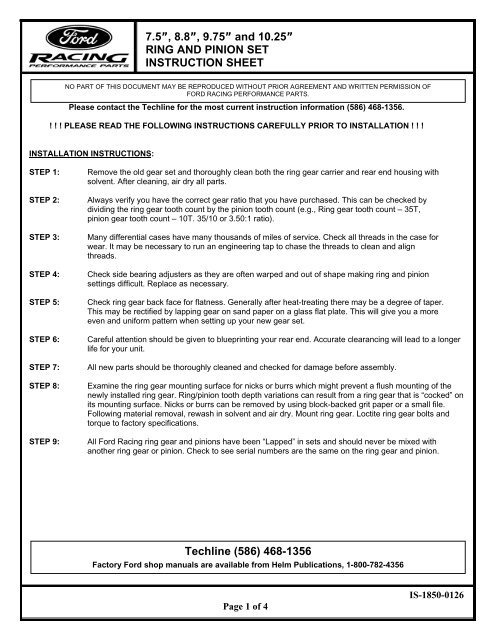
7.5”, 8.8”, 9.75” <strong>and</strong> 10.25”RING AND PINION SETINSTRUCTION SHEETNO PART OF THIS DOCUMENT MAY BE REPRODUCED WITHOUT PRIOR AGREEMENT AND WRITTEN PERMISSION OFFORD RACING PERFORMANCE PARTS.Please contact the Techline for the most current instruction information (586) 468-1356.! ! ! PLEASE READ THE FOLLOWING INSTRUCTIONS CAREFULLY PRIOR TO INSTALLATION ! ! !INSTALLATION INSTRUCTIONS:STEP 1:STEP 2:STEP 3:STEP 4:STEP 5:STEP 6:STEP 7:STEP 8:STEP 9:Remove the old gear set <strong>and</strong> thoroughly clean both the ring gear carrier <strong>and</strong> rear end housing withsolvent. After cleaning, air dry all parts.Always verify you have the correct gear ratio that you have purchased. This can be checked bydividing the ring gear tooth count by the pinion tooth count (e.g., <strong>Ring</strong> gear tooth count – 35T,pinion gear tooth count – 10T. 35/10 or 3.50:1 ratio).Many differential cases have many thous<strong>and</strong>s of miles of service. Check all threads in the case forwear. It may be necessary to run an engineering tap to chase the threads to clean <strong>and</strong> alignthreads.Check side bearing adjusters as they are often warped <strong>and</strong> out of shape making ring <strong>and</strong> pinionsettings difficult. Replace as necessary.Check ring gear back face for flatness. Generally after heat-treating there may be a degree of taper.This may be rectified by lapping gear on s<strong>and</strong> paper on a glass flat plate. This will give you a moreeven <strong>and</strong> uniform pattern when setting up your new gear set.Careful attention should be given to blueprinting your rear end. Accurate clearancing will lead to a longerlife for your unit.All new parts should be thoroughly cleaned <strong>and</strong> checked for damage before assembly.Examine the ring gear mounting surface for nicks or burrs which might prevent a flush mounting of thenewly installed ring gear. <strong>Ring</strong>/pinion tooth depth variations can result from a ring gear that is “cocked” onits mounting surface. Nicks or burrs can be removed by using block-backed grit paper or a small file.Following material removal, rewash in solvent <strong>and</strong> air dry. Mount ring gear. Loctite ring gear bolts <strong>and</strong>torque to factory specifications.All Ford Racing ring gear <strong>and</strong> pinions have been “Lapped” in sets <strong>and</strong> should never be mixed withanother ring gear or pinion. Check to see serial numbers are the same on the ring gear <strong>and</strong> pinion.Techline (586) 468-1356Factory Ford shop manuals are available from Helm Publications, 1-800-782-4356Page 1 of 4IS-1850-0126
7.5”, 8.8”, 9.75” <strong>and</strong> 10.25”RING AND PINION SETINSTRUCTION SHEETNO PART OF THIS DOCUMENT MAY BE REPRODUCED WITHOUT PRIOR AGREEMENT AND WRITTEN PERMISSION OFFORD RACING PERFORMANCE PARTS.STEP 10:Each Ford Racing ring gear <strong>and</strong> pinion is prerun <strong>and</strong> marked on the pinion face with its proper depthsetting called the “Checking Distance” (See Fig. 1). This dimension is from the face of the pinion to theaxle center-line. A setting tool must be used to measure the checking distance. <strong>Pinion</strong> depth is adjustedby adding or subtracting shim thickness. Stay +/-.002 of the pinion dimension (See Fig. 2).Fig. 1Fig. 2STEP 11:STEP 12:STEP 13:Once pinion depth is achieved using a new crush collar, set pinion bearing preload (see specificationchart on page 4). Once preload is set, install the seal <strong>and</strong> loctite pinion nut.Once the pinion gear is installed, position ring gear <strong>and</strong> carrier into housing. Ford Racing ring gear <strong>and</strong>pinions are developed to be run at .008” to .012” backlash for street gear sets.Adjustments for backlash are done by shim packs behind the carrier bearing cups. Always be sure carrierbearings are preloaded. The carrier should not fall out of the housing, but should have to be “tapped” induring final installation. Replace bearing caps <strong>and</strong> torque to factory specifications.Techline (586) 468-1356Factory Ford shop manuals are available from Helm Publications, 1-800-782-4356Page 2 of 4IS-1850-0126
7.5”, 8.8”, 9.75” <strong>and</strong> 10.25”RING AND PINION SETINSTRUCTION SHEETNO PART OF THIS DOCUMENT MAY BE REPRODUCED WITHOUT PRIOR AGREEMENT AND WRITTEN PERMISSION OFFORD RACING PERFORMANCE PARTS.STEP 14:You are now ready to verify the tooth contact pattern. A gear-marking compound should be used.Paint gear teeth with compound in several spots <strong>and</strong> rotate ring gear several revolutions. A toothcontact pattern will appear <strong>and</strong> should be similar to the pattern shown in Fig. 3. If the pattern is notin the approximate position shown, reset pinion depth <strong>and</strong> backlash to correct pattern. <strong>Pinion</strong> shimsusually must be moved in .003” increments to notice a pattern change. If a pattern is heavy toe,subtract shims (See Fig. 4). If a pattern is heavy heel, add shims (See Fig. 5).8620 Material (Street Sets)Correct Load PatternFig. 3Incorrect Pattern (Coast Side)Incorrect Pattern (Drive side)Fig. 4 Fig. 5STEP 15:Fill the case with required amount of EP85-90 gear lube, <strong>and</strong> maintain the proper level at all times.Proper maintenance is a must to protect your safety <strong>and</strong> the working life of your gear set.Properly designed, manufactured <strong>and</strong> maintained Ford Racing ring gear <strong>and</strong> pinions, correctly assembled by you ina clean, rigid gear box, <strong>and</strong> operated with the proper lubricant, should result in safe <strong>and</strong> satisfactory performance.Be sure application of your gear set is a correct one.Techline (586) 468-1356Factory Ford shop manuals are available from Helm Publications, 1-800-782-4356Page 3 of 4IS-1850-0126
7.5”, 8.8”, 9.75” <strong>and</strong> 10.25”RING AND PINION SETINSTRUCTION SHEETNO PART OF THIS DOCUMENT MAY BE REPRODUCED WITHOUT PRIOR AGREEMENT AND WRITTEN PERMISSION OFFORD RACING PERFORMANCE PARTS.TORQUE SPECIFICATIONSDescription 9.75” <strong>and</strong> 10.25” <strong>Ring</strong> Gear 7.5” <strong>and</strong> 8.8” <strong>Ring</strong> GearDriveshaft flange bolts 76 lb-ft with loctite 70-95 lb-ft with loctiteFiller Plug 22 lb-ft 15-30 lb-ftMinimum torque requiredto tighten pinion flange nut - 140 lb-ftto obtain correct pinionbearing preloadDifferential ring gear bolts 111 lb-ft 70-84 lb-ftDifferential pinion shaft lock bolt 22 lb-ft 15-30 lb-ftDifferential bearing cap bolts 77 lb-ft 76-89 lb-ftDifferential housing cover bolts 33 lb-ft 28-38 lb-ftSPECIFICATIONSDescription 9.75” <strong>and</strong> 10.25” <strong>Ring</strong> Gear 7.5” <strong>and</strong> 8.8” <strong>Ring</strong> GearBacklash between ring gear 0.203 mm-0.381 mm 0.203 mm-0.381 mm<strong>and</strong> pinion teeth (0.008 in-0.012 in) (0.008 in-0.012 in)<strong>Ring</strong> gear maximum variationbetween teeth 0.102 mm (0.004 in) 0.102 mm (0.004 in)Differential case maximum runout 0.076 mm (0.003 in) 0.076 mm (0.003 in)<strong>Pinion</strong> bearing preload(used pinion bearings) 0.9-1.5 Nm (8-14 lb-in) 0.9-1.5 Nm (8-14 lb-in)<strong>Pinion</strong> bearing preload(new pinion bearings) 1.8-3.3 Nm (16-29 lb-in) 1.8-3.3 Nm (16-28 lb-in)Techline (586) 468-1356Factory Ford shop manuals are available from Helm Publications, 1-800-782-4356Page 4 of 4IS-1850-0126