
You also want an ePaper? Increase the reach of your titles
YUMPU automatically turns print PDFs into web optimized ePapers that Google loves.
<strong>SIDE</strong>-<strong>POWER</strong>Thruster systemsSR 80/185 TSR 100/185 TGBNInstallation & User GuideInstallasjons- og brukerveiledningSLEIPNER MOTOR ASP.O. Box 519N-1612 FredrikstadNorwayTel: +47 69 30 00 60Fax: +47 69 30 00 70www.side-power.comsidepower@sleipner.noMade in Norway© Sleipner Motor AS 2009
GBContentsInstallation instructionsMeasurements, thruster..............................................................3Technical specifications ..............................................................4Thruster installationPositioning of the thruster unit ...................................................5Hatch cut out ..............................................................................6Fitting the hatch ........................................................................ 7Moulding .....................................................................................8Fitting the electromotor ..............................................................9Electrical installation .................................................................10Maintenance .............................................................................11Measurements, hatch ...............................................................12Template, holes in hatch ...........................................................13S-link installationSystem overview ......................................................................14Planning & precautions ............................................................15System schematics...................................................................16User’s manualGeneral use & alarm indications ..............................................17Installation checklist................................................................. 18Important user precautions ...................................................... 19Troubleshooting ....................................................................... 20Warranty statement .............................................................. 22Spareparts list & drawing .................................................... 23Service centres ..................................................................... 24DECLARATION OF CONFORMITYWe, Sleipner Motor ASP.O. Box 519N-1612 Fredrikstad, Norwaydeclare that this product with accompanyingstandard remote control systems complies withthe essential health and safety requirementsaccording to the Directive 89/336/EEC of 23May 1989 amended by 92/31/EEC and93/68/EEC.NInnholdInstallasjonsinstrukserMålskisse, truster........................................................................3Tekniske spesifikasjoner .............................................................4TrusterinstallasjonPlassering av enheten ...............................................................5Utskjæring av luke ......................................................................6Tilpassing av luke ..................................................................... 7Laminering ..................................................................................8Montering av elektromotor .........................................................9Elektrisk installasjon .................................................................10Vedlikehold ...............................................................................11Målskisse, luke .........................................................................12Mal, hull i luke ...........................................................................13S-link installasjonSystemoversikt .........................................................................14Planlegging og forbehold .........................................................15Koblingsskjema ........................................................................16BrukermanualBetjening og alarmindikering ...................................................17Sjekkliste ................................................................................. 18Viktige brukerforbehold ............................................................ 19Problemer og løsninger ........................................................... 20Warranty statement .............................................................. 22Deleliste/tegning ................................................................... 23Servicesentre ........................................................................ 24SAMSVARS ERKLÆRINGSleipner Motor ASPostboks 519N-1612 Fredrikstad, NorgeErklærer at dette produktet med tilhørendestandard kontrollsystemer er i samsvar medhelse, og sikkerhetskravene i henhold til Direktiv89/336/EEC FRA 23 Mai 89, korrigert av92/31/EEC og 93/68/EEC.
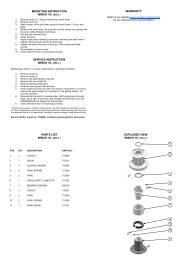
Loosen actuatorfrom frontmounting pointHullThruster casingCut, 45 degreechamfer outwardsWedges/shims inall four cornersGBFitting the hatchNTilpassing av luke7. Place unit according to marks and check that hull opening is correctlyplaced and is of correct size.Loosen actuator from front mounting point and carefully swing theretracting unit out of hull (people outside hull recommended to controlmoving part of thruster)Mount the hatch to the retract mechanism, fold mechanism back intohull, and remount actuator.With hach and actuator mounted, use wedges/shims in each corner ofthruster grp casing to make the hatch fit tight in the opening. The hatchshould be parallel with the hull on all edges, and the gap betweenhatch and hull should be equal on all four sides.When the casing is secured with the hatch in the correct place withwedges/shims, mould in the casing.Sleipner Motor AS recomends to use resin and fiberglass cuttingmixed to a paste to be used between casing and hull before moulding/laminating the casing to the hull - to avoid resin to flow into the casing,and to avoid the risk of getting the hatch stuck to the opening.7. Sett deretter enheten på plass over hullet, og kontroller at hullet erkorrekt og i riktig størrelse.Ta av aktuator i fremre innfesting og sving retracten forsiktig ut avskroget. Til denne jobben anbefales det at du har en hjelper på utsidenav skroget for å ta imot den utsvingbare delen på trusteren.Deretter skrus luken på plass på bunnrammen, og foldes inn og aktuatormonteres på igjen.Det er en fordel å se til at luken har en jevn tykkelse over det hele førden skrus fast, dette for en penest og best mulig installasjon.Når luke og aktuator er montert, shimses / kiles kassen i hvert hjørneinnvendig opp slik at luken passer perfekt i hullet.Luken skal ligge parallelt med skroget rundt og glippen mellom luke ogskrog skal være lik hele veien rundt.Når det er gjort, lamineres enheten fast.Sleipner Motor AS anbefaler å bruke f. eks. epoxy og glassfiberkuttingblandet til en fast masse som legges mellom enheten og skrogfør laminering. Dette for å unngå at det renner epoxy inn i enheten oglimer igjen luke til skrog.SR80/185T - SR100/185T 1.0.0 - 20097
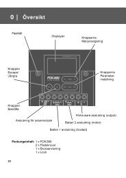
Profile, moulding 1Profile, moulding 2Profile, moulding 3 GBMouldingN Laminering8. The unit is now almost ready to be moulded to the hull (Epoxy andWR - woven rowing - recommended) Before starting to grind the hulland thuster casing, please cover thuster unit and inside of boat carefully.(Note, if the hull has a sandwich construction, all core material mustbe removed, and be rebuilt with WR by qualified personel)Begin grinding from inside of line drawn around thuster unit insidehull, starting with a depth of 2/3 hull thickness moving outwards withdecreasing depth.Grind thruster casing in similar manner, deepest on lower edge, decreasingupwards. Grind with power tool or by hand on inside of casing and inside ofmarking line on hull to accommodate 2-3 layers of WR9. After grinding and cleaning, place unit in final location and preparefor moulding. Mould the unit thoroughly to the inside of hull and fromoutside into casingRef illustration ”Profile, molding 1-3”.8. Nå er enheten klar for laminering (Sleipner Motor AS anbefalerepoxy og WR(vevd matte) glassfiber matte). Før du starter med å slipei skrog og glassfiberkassen på enheten må du være nøye med ogmaskere alt i båten og på enheten. (NB; Er skroget av sandwich type,må alt av kjernemateriale fjernes helt ut til det ytre skinnet av skrog, forså å bygges opp igjen med WR glassfiber matte)Slipingen starter på innsiden av streken som ble trukket rundt enheten på innsiden av skroget, og igjennom 2/3 av skroget og mindre ogmindre lengre ut til du er i null.Det samme gjøres på glassfiber kassen på enheten, slip mest på nedre kant og mindre oppover kasse.Slip også med verktøy eller for hånd på innsiden av glassfiber kassenpå enheten og på innsiden av streken på skrog, dette for og få heft tilto-tre lag med glassfiber matte her også.9. Etter sliping og grundig rengjøring plasseres enheten på plass,og du er nå klar for laminering. Enheten lamineres fast grundig påinnsiden av skroget, og på utsiden av skroget og inn i kassen.Se illustrasjon ”Profil laminering 1-3”.8 SR80/185T - SR100/185T 1.0.0 - 2009
Bolt tightening force (4x):SR80/100: 33 Nm (24 lb/ft)GBFitting the electromotorNMontering av elektromotor1. Remove the 4 bolts in the motor bracket.2. Place the motor gently on the motor bracket. Be careful, the motor isheavy! Ensure that key on axle and keyway in one-piece coupling arealigned. Ensure that you are placing the motor so that the cable terminalson it are available for electric installation later.3. Fasten the motor to the bracket with the 4 bolts and tighten them.4. Check if the springs for the brushes sit correctly on the brushes(see through the metal web around the top of the electromotor).5. Check the drive system by turning the propeller, it will be a littlehard to turn (because of the gear reduction and the motor), but youshould easily be able to turn it by hand.NB! Paint the gearhouse and propeller with antifouling for propellersto prevent growth of barnacles or similar which would reduce theperformance dramatically. Do not paint the propeller shaft, the zincanodesor the end face of the gearhouse.NB! Do not run the thruster for more than very short bursts withoutbeing in the water.NB! If the boat is still being built when the electromotor is installed, itmust be covered up to avoid dust from the building going into the motorand the solenoids. This cover must be removed before the thrusteris being used.1. Fjern de 4 boltene i motorbraketten.2. Plasser motoren på braketten. Plasser motoren slik at releene ertilgjengelige for tilkobling senere. Ta hensyn til at motoren er tung nården bæres og håndteres.Sjekk at kilespor i gummikobling og kile på aksel er på linje.3. Fest motoren til braketten med de fire boltene.4. Sjekk at børstefjærene sitter korrekt på børstene (gjøres ved å segjennom gitteret på siden av motoren).5. Test installasjonen ved å dreie på propellen. Det vil være motstandpga. girutveksling og motor, men det skal enkelt la seg gjøre å dreiepropellen for hånd.NB ! Påfør bunnstoff på girhus og propell for å unngå vekst som kan virkesterkt hemmende på thrusterens effekt. Sinkanoder propellaksling ogtetninger skal ikke stoffes.NB ! Thrusteren må kun kjøres i meget korte perioder når den ligger påland.NB ! Hvis båten fortsatt er under bygging når thrusteren blir montert måmotoren dekkes til for å unngå at støv og lignende trenger inn i girhus ogelektromotor. Dekket må fjernes før motoren tas i bruk.SR80/185T - SR100/185T 1.0.0 - 20099
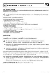
Check and relubricatewith waterproof grease ifneccessaryZinc anode,retract mechanismZinc anode,gearlegGBMaintenanceNVedlikehold» Retighten the bolts holding the gearhouse to the motor bracketduring the first on-land service with the specified bolt tighteningforce (see page 9).» Keep the propeller and gearhouse clean from growth by paintingwith antifouling before every season.PS! The zinc anode, sealing and propeller shafts must absolutelynot be painted. Be careful that you don’t fill paint in the “tracks”in the gearhouse that the propeller hub moves in.» Change the zinc anode before every season, or when about halfthe anode is gone. Always use a sealant on the screw holding thezincanode to ensure that it does not fall off. Please observe that insome waterconditions it can be necessary to install an extrazincanode to ensure that it lasts for the whole period betweenregular service lifts of the boat. Consult your dealer for informationon how to do this.» As a part of the seasonal service of your boat, and before everyseason, always check that:• The propeller is securely fastened• The bolts holding the electric motor to the motor bracket arefastened correctly.• The universal joint in the retract mechanism is lubricated• The area where the thruster is installed is clean and dry. If thereare signs of water you must try to find the source and eliminate it.• All electrical connections are clean and fastened firmly.• Make sure that your batteries are in a good condition so that thethruster gets a good voltage. Old or bad batteries will give areduced performance from the thruster.» Etterstram boltene som holder girhuset sammen med braketten vedførste på-land servicen med oppgitt moment (s. 9).» Hold propellen og girhuset fritt for algevekst ved å påføre bunnstoff førhver sesong.PS ! Sinkanoder, tetninger og propellaksel skal ikke påføresbunnstoff, pass på så det ikke kommer bunnstoff i gjengesporenetil propellmutteren.» Skift sinkanode før hver sesong, eller når ca. halvparten av sinkanodenhar tæret bort. Bruk Locktite eller lignende på skruen tilsinkanoden for at den ikke skal falle av. Ta i betraktning at under noenvannforhold er det nødvendig å montere en ekstra sink-anode for åvære sikker på at de skal vare i hele perioden mellom vedlikehold. Takontakt med din forhandler for informasjon om hvordan å gjøre dette.» Som en del av det periodiske vedlikeholdet av din båt, og før hversesong må følgende ting sjekkes:• Propellen sitter godt festet.• Boltene som holder elektromotoren til braketten sitter.• At universalleddet i retract-mekansimen er smurt• Skottet der baugpropellen er montert skal være rent, og tørt. Hvis deter vann i skottet må lekkasjen finnes og tettes.• Alle elektriske tilkoblingspunkter er rene, og godt festet.• Pass på at batteriene er i god stand slik at de kan gi høy spenning tiltrusteren. Redusert spenning vil gi redusert effekt på trusteren.SR80/185T - SR100/185T 1.0.0 - 200911
GBMeasurements, hatchNMålskisse, lukeMeasurements, outside - gelcoat sideInner cut lineMeasurements, inside12 SR80/185T - SR100/185T 1.0.0 - 2009
GBTemplate, holes in hatchNMal, hull i lukeAlign with inner rear cut-out line,hatchRett inn etter indre bakrekuttmarkering for luke SR80/185T - SR100/185T 1.0.0 - 200913
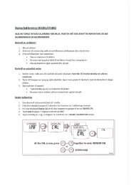
Retractpanelred5A+12VBatteryPower supplycableblackyellow12VManual main switchT-connector T-connector T-connectorMain fuseTerminator120 ohm8730Terminator120 ohm+ -MController6 1242FootSwitches( opt.)Remote control(opt.)ActuatorRetractthrusteroptionalSetup with manual main switchRetractpanelPower supplyWiring cable Retract thrusterW / manual main switchred5Ablackyellow+12VBatterySleipner Motor ASP.O. Box 51912VN-1612 FredrikstadNorwayTel: +47 69 30 00 60Drawn:L.G. 8.6.09Draw no:RTS-A00-652-01T-connector T-connector T-connectorAutomaticMain Switchw/S-linkTerminator120 ohm8730Terminator120 ohm+ -MController6 1242FootSwitches( opt.)Remote control(opt.)ActuatorRetractthrusteroptionalSetup with automatic main switchGBS-link system schematicsNS-link koblingsskjemaThe S-link control system is powered by a dedicated power cable connectedto the system backbone as a normal spur cable.The cable ends connect to battery pos. and battery neg. and the cableshield connects to battery neg.The battery pos. must be connected through a 5A fuse.S-link systemeter strømforsynt via en dediker strømkabel som kobles tilsystemets “backbone” som en normal “spur”-kabel.Kabelendene kobles til batteriets pluss- og minuspol og skjermkabelenkobles til batteriets minuspol.Sleipner Motor AS Drawn:L.G. 8.6.09Wiring Retract thrusterP.O. Box 519W / Automatic Ledningen Main som SwitchN-1612 Fredrikstadkobles til batteriets plusspol må Norway sikres med en Draw 5A no: sikringRTS-A00-651-01Tel: +47 69 30 00 6016 SR80/185T - SR100/185T 1.0.0 - 2009
Green status LEDRED status LEDYELLOW status/on-off LEDGBGeneral use & alarm indicationPANEL ON: push both “ON” buttons simultaneously, thruster deploys.PANEL OFF: push “OFF” button, thruster retracts.Operate thruster by pushing red and green arrows.STATUS/ALARM LEDS:GREEN LED flashes during deploy phase, Solid GREEN LED indicatesthruster deployed and ready to operate.RED LED flashes during retract phase, all LEDs out when panel/thrusteris shut down.If something unexpected happens while deploying/retracting thruster,the LEDs will show alarm codes according to form below:NBetjening og alarmindikeringPANEL PÅ: Trykk begge “ON”-knappene samtidlig og trusteren felles utPANEL AV: Trykk på “OFF”-knappen og trusteren felles inn.Betjen trusteren ved hjelp av den røde og grønne pilknappen.STATUS OG ALARM LED:GRØNN LED blinker mens trusteren felles ut, fast lysende GRØNN LEDforteller at trusteren er ute og klar til bruk.RØD LED blinker under innfelling av trusteren, alle LED-er slukkes nårtrusteren er inne og systemet er slått av.Hvis noe uforutsett inntreffer mens trusteren felles ut eller inn, vilLED-ene vise alarmkoder i henhold til tabellen under: •• 1 flash YELLOW & GREEN - Pause Thruster, overtemp Retracts Turn off panel, wait for 20 mins.•• 2 flashes YELLOW & GREEN - Pause Thruster, low power Retracts Turn off panel, charge batteries.•• 2 flashes YELLOW & RED - Pause Thruster IPC error Retracts Turn off panel - thruster must be serviced byauthorized personel.•• 3 flashes YELLOW & GREEN - Pause Deploy operation obstructed Retracts Turn off panel. Go for lower speed/deeperwater. Retry.•• 3 flashes YELLOW & RED - Pause Retract operation obstructed Aborts retract, deploys and retries toretract 3 times. If operation still isobstructed, retract stops on obstructionPress both ON-buttons to deploy thruster.Turn main switch off. Remove obstruction.•• 1 flash YELLOW & RED - Pause Power failure, Actuator System shuts down Turn off panel. Check actuator connections .Retry.••• 4 flashes YELLOW, GREEN & RED -PauseNo contact with thruster None Turn off panel. Check main switch, fuse, cableconnections, cables. Retry. •• 1 blink GUL & GRØNN - Pause Truster, overtemperatur Felles inn Slå av panel, vent 20 minutter.•• 2 blink GUL & GRØNN - Pause Truster, lite strøm Felles inn Slå av panel, lad batteriene.•• 2 blink GUL & RØD - Pause Truster IPC feil Felles inn Slå av panel - trusteren må repareres avkvalifisert personell.•• 3 blink GUL & GRØNN - Pause Utfellingav truster hindres Felles inn Slå av panel. Kjør saktere eller på størredybde. Prøv igjen .•• 3 blink GUL & RØD - Pause Innfelling av thruster hindres Avbryter innfelling, felles ut og prøver åfelle inn 3 ganger. Hvis innfellingenfremdeles er hindret, stopper bevegelsenTrykk begge ON-knappene for å felle trusterenut. Skru av hovedstrømsbryter. Fjern det somhindrer bevegelsen.ved hindringen•• 1 v GUL & RØD - Pause Strømfeil, Aktuator Systemet slår seg av Slå av panel. Sjekk elektriske koblinger tilaktuator. Prøv igjen.••• 4 blink GUL, GRØNN & RØD - Pause Ingen kontakt med truster Ingen Slå av panel. Sjekk hovedbryter, sikringer, el.koblinger, kabler. Prøv igjen.NB: THE MAIN SWITCH MUST BE TURNED OFF IMMEDIATELYWHEN AN IPC-ERROR OCCURS, TO PREVENT OVERHEATING OFTHE THRUSTER MAIN RELAYS!THRUSTER WILL NOT RETRACT WHILE REVERSING AT “HIGH”SPEED. THIS WILL TRIGGER THE “Retract operation obstructed”ALARM.IF ALARM IS TRIGGERED, REDUCE SPEED AND PRESS BOTH “ON”BUTTONS BEFORE RETRYING “OFF” BUTTONNB: VED IPC-FEIL MÅ HOVEDSTRØMSBRYTER SLÅS AV UMID-DELBART FOR Å FORHINDRE VARMEUTVIKLING I TRUSTERENSHOVEDRELER !THRUSTER FELLES IKKE INN VED BAKKING I ”HØY” FART.DETTE VIL UTLØSE ALARM ”Innfelling av thruster hindres”.HVIS ALARM UTLØSES, REDUSER FARTEN OG TRYKK BEGGE”ON” KNAPPENE FØRST FØR ”OFF” TRYKKES PÅ NYTT.C:\Documents and Settings\kai\Desktop\retract alarms.xlsx SR80/185T - SR100/185T 1.0.0 - 200917
GBChecklistNSjekkliste Propeller is fastened correctly to the shaft. Propeller turns freely in tunnel. The zinc-anode holding screw is tightened well with thread glue. Anti-fouling have been applied to the gearhouse and propeller butNOT on the zincanode or the gearhouse lid where the propeller isfastened. The brush springs are fitted correctly on the brushes in the electromotor(check through the grid around the top end of the motor). Correct drive direction as per controlpanel. All electrical connections are clean, dry and tight, and the correctcable, fuse and main switch sizes have been used. With a ohm meter check that there is no electrical connectionbetween electromotor body and positive terminal on the motor andbetween the electromotor body and the negative (A1) terminal onthe motor. The bolts holding the gearhouse and motorbracket together aretightened correctly. The bolts holding the electromotor to its bracket are tightenedcorrectly.Propellen er festet til akselen på korrekt vis.Propellen roterer fritt i tunnel.Festeskruen til sinkanoden er festet med gjengelim.Bunnstoff er påført girhus og propell, men ikke på sinkanode,tetninger eller propellaksel.Børstefjærene er riktig plassert mot børstene. Dette sjekkes ved å segjennom gitteret på siden av motoren.Kontrollpanel gir korrekt kjøreretning på thrusteren.Alle elektriske koblinger er rene, tørre og tette. Korrekte kabler,sikringer og hovedstrømsbryter er brukt.Boltene som festet braket til girhus er festet korrekt.Boltene som festet motor til braket er festet korrekt.The thruster has been installed as per the instructions in this manual andall points in checklist above have been controlled.Thrusteren er installert i henhold til instuksene gitt i denne manualen, ogalle punkter i sjekklisten er kontrolert.Signed: ................................................ Date:...............................Extra pre-delivery tests by installer/yard who does not use otherquality control systems !Thruster type: .................................................. Voltage: ....................Serial number: ................................. Date of delivery: .......................Correct drive direction as per control panel: .....................................Voltage at thruster when running: ......................................................Battery cable size used: .....................................................................The compartment where the thruster is fitted is isolated from general bilgewater and has no obvious or suspected risks for flooding.Other comments by installer:Signatur: ............................................... Dato: ................................Anbefalt før leverings test for installør / verft som ikke bruker andrekvalitetskontroll systemer!Thrustertype: ................................................ Volt: .............................Serienummer: .....................................................................................Leveringsdato: ....................................................................................Korrekt kjørerettning per kontrollpanel: ..............................................Spenning målt på thruster under kjøring: ...........................................Strømkabler: .......................................................................................Skottet hvor thrusteren er montert er isolert fra kjølvann og har ingenåpenbar risiko for lekkasje.Kommentar fra installør:18 SR80/185T - SR100/185T 1.0.0 - 2009
GBImportant user precautionsNViktige brukerforbehold• Ensure that you know the location of the main battery switch thatdisconnects the thruster from all power sources (batteries) so thatthe thruster can be turned off in case of a malfunction.• Always turn the main power switch off before touching any part ofthe thruster, as an incidental start while touching moving parts cancause serious injuries.• Always turn the control device off when the thruster is not in use.• The maximum continous usage time of the electrical thruster isapproximately 3 minutes. The electromotor has a built in thermalcut-off switch that will shut off the electromotor if it is overheatingand re-engage it when it has cooled down some. This should beconsidered when planning your maneuvering.• This also means that the thruster will limit its total running time pertime period so that you can not count on the thruster to hold youin a current and side wind for extensive time periods. Dependingon the surrounding temperatures etc. the thruster will be able torun approximately 10 % of the time.• Never use a thruster close to somebody in the water, as thethruster will draw objects close by into the tunnel and contact withthe rotating propellers will cause serious injuries.• With the boat on land, only run the thruster for a fraction of asecond, as without resistance it will accelerate very fast to adamaging rpm. Also, while the thruster is in air, make sure that thepropellers have come to a complete stop before performing adirections change of the thruster, as it might cause damage to thethruster.• If the thruster stops giving thrust while the electromotor is running,chances are that there is a problem in the drive-system. You mustthen immediately stop trying to run it, and turn it off, as running theelectromotor for more than a few seconds without resistance fromthe propeller, can cause serious damage to the electromotor.• When leaving the boat always turn off the main power switch forthe thruster.• We advice to always keep the main engine(s) running while using athruster. This will keep the batteries in a good charge condition. Thiswill also give better performance to the thruster, as a higher voltageat the thruster results in a higher torque (power) in the electromotor.• Please note that the performance of a thruster strongly depends onthe voltage available at the electromotor. This voltage will decreaseby time because aging batteries have a reduction of capacity. Byinstalling new batteries the effect of the thruster should be back atthe original level.• Forviss deg om at du kjenner plasseringen av hovedstrømsbryterentil baugtrusteren, som kutter all strøm til trusteren, så trusteren kanskrus av i nødstilfelle.• Før berøring av noen del av trusteren må alltid strømmen skrus av.En uønsket start kan volde stor fysisk skade.• Skru alltid av kontrollpanelet etter bruk.• Den maksimale sammenhengende kjøretiden for en elektrisk trusterer ca. 3 min. - da vil en føler automatisk skru av motoren når dennår en viss temperatur. Dette må tas i betraktning når en manøverplanlegges.• Dette betyr at ved manøvere som tar lang tid vil ikke trusteren kunnebrukes hele kontinuerlig. Ved manøvere som tar lang tid kan manbruke trusteren i ca 10 % av tiden, avhengig av temperaturen i vannet.• Bruk aldri trusteren når noen er i vannet, trusteren vil trekke gjenstandertil seg og kontakt med propellen vil volde alvorlig skade.• Kjør aldri trusteren i mer enn 1 sek. når båten er på land. Uten motstandfra vannet vil thrusteren nå ødeleggende turtall svært fort.• Hvis thrusterne stopper å gi skyvekraft mens motoren er i gang, erdet trolig oppstått problemer i girsystemet. Stopp umiddelbart å kjøremotoren, og skru den av. Uten motstand fra vannet vil thrusteren nåødelegende turtall svært fort.• Når man forlater båten skal alltid hovedstrømsbryteren slås av.• Vi anbefaler å ha motoren i gang når trusteren kjøres. Da vil batterienvedlikeholdes, og det vil være høyere spenning til elektromotoren.Høyere spenning gir høyere turtall og bedre ytelse.• Ytelsen til en baugtruster avhenger av hvilken spenning motorenmottar under kjøring. Kapasiteten til batterier avtar etter hvert somde blir eldre, og dermed også ytelsen til trusteren. Ved å installerenye batterier vil trusteren yte maksimalt igjen.• Kun en kontroll skal brukes av gangen, hvis to kontroller brukesmotsatt vei vil trusteren stoppe automatisk. Hvis to paneler opereressamme vei vil ikke dette skje.• Hvis trusteren ikke fungerer tilfredsstillende må feilen lokaliseresog rettes så snart som mulig, for at ikke trusteren skal ta ytterligereskade, skru av hovestrømsbryteren hvis feilen er av elektrisk art.• Make sure that only one control is used at the same time, if twopanels are operated in opposite directions at the same time thethruster will not run at all. If they are operated in the same directionthe thruster will run in this direction.• If the thruster is not performing or functioning as usual, the cause forthis must be found and corrected as soon as possible so to avoidcausing any other or further damage to the equipment. You mustalso turn off the main battery switch immediately in case theproblem is of electric origin.• Never store anything (e.g. equipment, sails, ropes etc.) in thesame compartment as the thruster. When the thruster runs fora longer period it will get hot and will cause damage.SR80/185T - SR100/185T 1.0.0 - 200919
GBTroubleshootingBefore seeking assistance at the help desk of your Sidepower dealer/distributor please perform these tests and make notes ofall measurements to ensure that they have as much information as possible to work on.NB! All check points and solutions must be carried out after consulting the relevant information elsewhere in this manual to understandhow the system is intended to work. If you are unable to understand what to check, you must consult a professional.Check» The electromotor runs, but there is no thrust.If the flexible coupling between the motor and driveshaft isnot fitted correct inside the boat.SolutionCheck the flexible coupling/shear pin and the motor installation to ensure correct connectionof the flexible coupling before re-fitting the electromotor.Are the propellers in the tunnel fastened correctly on theprop-shaft (key/drive pin present)With the motor removed, turn the driveshaft from insidethe boat to feel if the gears are engaging and turning theprop-shaft.Re-fasten or replace the propeller and/or key/drive pin.In case of a failure inside the gearhouse, we advice to get a replacement gear-houseinstead of attempting to repear the internal gear and bearing system.» The thruster does not start at all or works only in one direction.Check that the voltage of the electromotor is correct foryour installation by their labels.If wrong, contact your dealer or distributor to obtain parts with the correct voltage.Check the voltage at the thruster between main minus input(A1 on motor) and main plus input point:Check the voltage at the thruster while you are trying torun it. Keep main engine(s) running to have continouscharge to the batteries.The no load voltage should be:12V system =12,7V / 24V system = 25,4 V. If below 12,3V / 24,6V your batteries arenot in a good charge state or worn out and must be recharged or replaced before tryingto run the thruster.If less than 8,5V at the thruster the voltage is to low for the thruster to operate correctly.Find and correct the reason for this low voltage which will probably be one or more ofthese points: main battery cable sizes and connections, battery size and condition, fuseand main power switch performance.If the main solenoids on the thruster are not even trying toengage (clicking) they are probably not getting a "run" signalfrom the control system. Try to run the thruster withoutthe panel by directly connecting the red and the blue or thered and the grey wires in the controlcable contact comingfrom the thruster.If the thruster runs in both directions, try the same in the connector that goes into theback of the control panel. If it also works in this position, check the contact and wireson the back of the panel and try to engage this again by pushing both ON buttonssimultaneously. If the panel does not turn on (see control light), measure the voltagebetween the Red and the Black in the contact going into the thruster. If the voltage isgood, chances are that the panel is not working.If it works by the thruster, and not by the panel there is a bad contact or a broken leadthe control cables between these two test points.Measure that you have the correct voltage between the Red (+) and all the other coloursin the contact. If you do not get a reading.If the thruster does not run at all, or only in one direction inthe above tests, check the internal wiring on the thrustermotor, solenoids and electronic motor inter-face box to bein accordance with the wiring diagram and ensure that allconnections are clean and tight.Between main minus (A1 on motor) and the blue and the grey wire connected to thesides of the main solenoids you should have the same voltage as betweenthe main battery cables on the thruster. If not, check that the internal wiring on the solenoidis ok and measure that there is contact through the magnetising spools of eachside of the solenoid (measure between the red and blue on one side, and red and greyon the other side with an Ohm meter.). If there is nocontact between these, the solenoid is broken and needs replacing.» The thruster has an unexpected low performance.Check voltage at thruster when running.Check that all the brush-springs sits correctly on the brushesin the electromotor.Check that the propeller, gearhouse and tunnel is freefrom growth/barnacles etc.If less than 10,5 V / 21V the thruster will not perform at specified effect.If one or more brushes are loose/has no tension from the brush-spring, the performancewill be low.If there is growth in the tunnel, this will disturb/block the waterflow and especially barnacleson the propeller will greatly reduce performance.» The thruster runs for approximately 0,5 seconds every 4 seconds.Solenoid flapping, most probable cause:low voltage.Re-charge battery(ies), if this is not sufficient, replace battery(ies).Check for bad cable connections, if necessary tighten/re-adjust connections.Check cable size in accordance to manual.» The thruster runs for approximately 0,5 seconds every 10 seconds.Solenoid lock-in, auto stop of thruster, auto retry every 10seconds.Shut off thruster main switch, tap slightly on the solenoid to see if it will release. Turnon thruster main switch. If solenoid is still in lock-in mode, replace solenoid.20 SR80/185T - SR100/185T 1.0.0 - 2009
NProblemer og løsningerFør du søker hjelp hos din forhandler kan du foreta noen tester, og notere ned resultatet for at forhandleren skal ha mestmulig informasjon til rådighet.NB ! Alle sjekkpunktene på listen må sammenlignes med informasjon gitt tidligere i manualen for å forstå hvordan systemetskal fungere. Hvis du ikke forstår sjekklisten eller de relevante opplysningene gitt i manualen så må du ta kontakt medprofesjonell hjelp.Kontroller» Elektromotoren går, men det er ingen skyvekraft.LøsningBrytepinnen mellom motoren og drivakselen kan være hablitt brutt av.Er propellen festet til propellakselen, og er drivpinne påplass.Med elektromotoren avmontert, kan drivakselen vris forhånd for å sjekke om gir, og lager er i orden.Sett i ny brytepinne og sjekk motorinstallasjonen.Fest eller erstatt propellen og drivpinnen.I tilfelle girhuset er skadet anbefaler vi skifte girhus, fremfor å prøve å reparere innvendigegir og lagre.» Trusteren går bare i en retning, eller ikke i det hele tatt.Kontroller at elektromotoren er beregnet for riktig spenningi forhold til dinKontakt din forhandler for å skaffe deler beregnet for riktig spenning.installasjon.Sjekk spenningen mellom positiv og negative koblingenepå motoren.Spenningen skal være 12,7 V / 25,4 V når thrusteren ikke kjøres.Hvis spenningen er under 12,3 V / 24,6 V må batteriene lades, eller skiftes ut før thrusterenkjøres.Sjekk spenningen mellom motorens negative og positivekoblinger under kjøring av trusteren. Hold hovedmotoren igang for å sikre kontinuerlig ladning av batteriene.Ved 8,5 V spenning, eller lavere vil ikke motoren kunne kjøres. Finn og rett opp feilensom skaper lav spenning. Feilen vil ofte være hovedstrømkablene og koblingene,Spenningsfall over sikring eller hovedstrømsbryter, batteriets størrelse/tilstand.Hvis hovedreleet på trusteren ikke slår inn i det hele tatt(det skal klikke når du prøver å kjøre trusteren), så er detet tegn på at det ikke får signal fra kontrollpanelet. Prøvda å kjøre trusteren uten panelet ved å koble Rød og Blå,eller Rød og Grå kabel sammen på kontrolpanelkabelensom kommer fra trusteren.Hvis trusteren kjører i begge retninger prøv samme framgangsmåte på koblingen somgår inn bak på kontrollpanelet. Hvis trusteren fungerer må koblingene og kontaktpunktenepå kontrollpanelet sjekkes. Prøv panelet igjen ved å trykke inn begge ON knappenesamtidig. Hvis panelet ikke fungerer (sjekk kontroll lyset mellom ON knappene)må spenningen mellom Rød og Svart ledning som går inn i panelet. Hvis spenningener bra er trolig panelet defekt.Hvis du får motoren til å kjøre ved trusteren, men ikke ved panelet så er problemetdårlig kontakt eller ledningsbrudd.I tilfelle trusteren ikke går i det hele tatt, eller bare i enretning i de tidligere testene. Sjekk at koblinger gjort påelektromotoren, rele og forsinkelsesrele er i henhold tilkoblingskjema, og at alle kontakter sitter godt, og er rene.Spenningen målt mellom hovedstrøms minus (A1 på motor), og blå eller grønn ledningpå releet skal være lik spenningen mellom de to hovedbatterikablene på trusteren. Hvisspenningen ikke er riktig, må det kontroleres at det er kontakt mellom de magnetiskespolene på hver side av releet (mål mellom rød og blå på motsatte sider, og rød og gråpå motsatte sider, med et OHM-Meter).Hvis det ikke er kontakt mellom disse må releet skiftes ut.» Trusteren yter mindre enn ventet.Mål spenningen på motoren under kjøring.Sjekk at alle børstefjærene ligger riktig an mot børstene.Er spenningen lavere en 10,5V / 21V vil trusteren sunke i turtall og skyvekraften senkes.Trusteren vil ha lav skyvekraft hvis en eller flere børster ikke får trykk fra fjærene.Kontroller propell, girhus og tunnel, og fjern eventuellalgevekst og lignende.Algevekst i tunnelen vil redusere vannstrømmen, algevekst på propellen kan redusereytelsen betydelig.» Trusteren kjører i ca. 0,5 sekunder hvert 4 sekund.Relé ”slår / klapprer” – forårsakes som oftest av for lavspenning .Batterilading er nødvendig – eventuelt bytt ut defekte batterier.Kontroller alle kabeltilkoblinger for dårlig kontakt – sørg for god kontakt.Kontroller at kabler har riktig tverrsnitti henhold til manual.» Trusteren kjører i ca. 0,5 sekunder hvert 10 sekund.Relèet er brent fast – Automatisk stopp av trøster. Forsøkerreststart av trøster hvert 10 sekund for å se om feilener rettet.Bryt hovedstrømmen til trøster med hovedstrømsbryteren og dunk forsiktig på relé forå se om kontaktflatene slipper. Slå på hovedstrømbryter og se om feilen er fikset. Omden vedvarer må relé byttes.SR80/185T - SR100/185T 1.0.0 - 200921
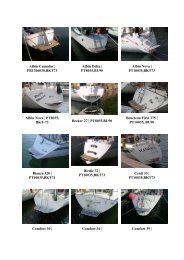
Partslist, SR80/185T & SR100/185TSP 75 Ti27 3024 2720 16 19 1729 26 28 25 26 23 25 22 24 21 23 20 22 19 21 1815 16 14 18 13171215 1110 141312 9761187108 88911345 126 2 1345 1 22 1 3 4 5Ref: 12V 24V30. Complete electric motor assembly Part # 6 0101 12 6 Part 0101 24 #29. Nut for solenoid cover 6 8810 6 8810Ref:12V 24V 12V 24V28. Solenoid cover 6 2025 6 202527 Complete electric motor assembly 6 0104 12 6 0104 24 8 0105 12 8 0105 2427. Complete solenoid kit 6 0131 12 6 0131 2426 Nut for 26. solenoid cover Solenoid 6 8810 6 8810 41371123 6 8810 41371243 6 881025 Solenoid 25. Cover Internal w iring loom 6 2025 6 2025 6 1226B 6 2025 6 1226B 6 202524 Complete 24. solenoid Electronic kit control box 6 0132 12 6 0132 24 6 1232i 6 0132 12 6 1232i 6 0132 2423. Solenoid bracket kit 6 0135 6 013523 Solenoid 41371123 41371243 1013713 4137124322. Key for electric motor shaft 10 1440 10 144022 Internal wiring loom 6 1227 61227 6 1227 6 122721. Electric motor N/A N/A21 Electronic control box 6 1242 6 1242 6 1242 6 124220. Brush springs for electric motor (kit) 6 0170 12* 6 0170 24*20 Solenoid 19. bracket Brushes kit for electric motor 6 0136 (kit) 6 0136 6 0180 8 12* 0136 6 0180 8 24* 013619 Key for 18. eletric Complete motor shaft flexible coupling 10 1440 10 1440 7 1450 10 1440 7 1450 10 144018 Electric 17. motor Rubber element N/A N/A 7 1451 N/A 7 1451 N/A17 Brush 16. springs Oil container for motor (kit) w ith holder 6 0170 12* 6 0170 24* 20 0300 8 0170 12* 20 0300 8 0170 24*15. Oil hose w ith hose clamps 20 0400 20 040016 Brushes for motor (kit) 6 0180 12* 6 0180 24* 8 0180 12* 8 0180 24*14. Complete motor bracket 8 0500 8 050015 Actuator, complete 6 2300 6 2301 6 2300 6 230113. O-ring seals in motor bracket 7 1340 7 134014 End stop12.sensorCompletekitgearleg6 2103 6 2104 8 0600 6 2103 8 0600 6 210413 Complete 11. flexible Gearleg coupling bolt 7 1462 7 1462 7 1080 7 1462 7 1080 7 146212 Support 10. stay set Drive shaft seal 6 2200 6 2200 7 1350 6 2200 7 1350 6 220011 Zink Anode, 9. retract Drive mechanism shaft key 3 1180 3 1180 6 1440 3 1150 6 1440 3 11808. Propeller shaf t seal 6 1350 6 135010 Complete motor bracket 8 0503 8 0503 8 0503 8 05037. Gasket 8 0610 8 06109 Complete gearleg 8 0601 8 0601 8 0601 8 06016. Oil drain screw w ith gasket 6 1220 6 12208 Gearleg bolt 7 1080 7 1080 7 1080 7 10805. Zinc anode 7 1190 7 11907 Driveshaft 4. key Locknut 6 1440 6 1440 4 1260 6 1440 4 1260 6 14406 Gasket 3. Propeller w asher 8 0610 8 0610 7 1181 8 0610 7 1181 8 06105 Zink anode 2. Propeller drive pin 7 1190 7 1190 6 1241 7 1190 6 1241 7 11904 Locknut 1. Propeller 4 1260 4 1260 7 1260 4 1260 7 1260 4 12603 Propeller washer 7 1181 7 1181 7 1181 7 1181Other comments:2 Propeller drivepin 6 1241 6 1241 6 1241 6 1241*Original modelOriginal modelModel periodModel periodSR 80/185T06/09
Service CentresArgentinaTrimer SABuenos AiresTel: +54 11 4580 0444Fax: +54 11 4580 0440www.trimer.com.artrimer@trimer.com.arAustraliaAMI SalesFreemantle, WATel: +61 89 331 0000Fax: +61 89 314 2929ami@amisales.com.auAustriaG. Ascherl GmbHHard, BregenzTel: +43 5574 899000Fax: +43 5574 89900-10www.ascherl.atoffice@ascherl.atBeneluxASA Boot ElectroWatergangTel: +31 20 436 9100Fax: +31 20 436 9109www.asabootelectro .nlinfo@asabootelectro.nlBrazilElectra Service Ltda.GuarujaTel: +55 13 3354 3599Fax: +55 13 3354 3471www.electraservice.br.comalbertoni@electraservice.com.brBulgariaYachting BGBurgastel: +359 56 919090fax: +359 56 919091www.yachting.bginfo@yachting.bgCanadaImtra CorporationNew Bedford, MATel: +1 508 995 7000Fax: +1 508 998 5359www.imtra.comside-power@imtra.comChina/Hong KongStorm Force Marine Ltd.Wanchai, Hong KongTel: +852 2866 0114Fax: +852 2866 9260www.stormforcemarine.comsales@stormforcemarine.comCroatiaAC Yacht & nautical supportIciciTel: +385 51 704 500Fax: +385 51 704 600acy@net.hrCyprusOcean Marine Equipment LtdLimassolTel: +357 253 69731Fax: +357 253 52976oceanm@spidernet.com.cyDenmarkGertsen & Olufsen ASHørsholmTel: +45 4576 3600Fax: +45 4576 1772www.gertsen-olufsen.dkinfo@gertsen-olufsen.dkEstonia/Latvia/LithuaniaMiltec Systems OÜTallinTel: +372 5013997Fax: +372 6442211www.miltec.eetony@miltec.eeFinlandNautikulma OYTurkuTel: +358 2 2503 444Fax: +358 2 2518 470www.nautikulma.finautikulma@nautikulma.fiFranceKent Marine EquipmentNantesTel: +33 240 921 584Fax: +33 240 921 316www.kent-marine.comcontact@kent-marine.comGermanyJabsco GmbHNorderstedtTel: +49 40 535 373-0Fax: +49 40 535 373-11GreeceAmaltheia MarineAthensTel: +30 210 2588 985Fax: +30 210 2588 986www.amaltheiamarine.comamalmar@otenet.grIcelandMaras EHFReykjavikTel: +354 555 6444Fax: +354 565 7230www.maras .isgummi@maras .isIndiaIndo Marine Engineering Co. Pvt. LtdPune, MaharashtraTel: +91 20 2712 3003Fax: +91 20 2712 2295siddharth@indogroup-asia.comIrelandSleipner Motor Ltd.South BrentTel: +44 1364 649 400Fax: +44 1364 649 399andy@sleipner.co.ukIsraelAtlantis Marine Ltd.Tel AvivTel: +972 3 522 7978Fax: +972 3 523 5150www.atlantis-marine.comatlantis@inter.net.ilItalySaim S.P.A.Assago-MilanTel: +39 02 488 531Fax: +39 02 488 254 5www.saim-group.comJapanTurtle Marine Inc.NagasakiTel: +81 95 840 7977Fax: +81 95 840 7978www.turtle-marine.cominfo@turtle-marine.comMaltaS & D Yachts Ltd.CaliTel: +356 21 339 908Fax: +356 21 332 259www.sdyachts.cominfo@sdyachts.comNew ZealandAdvance Trident Ltd.AucklandTel: +64 9 845 5347Fax: +64 9 415 5348www.advancetrident.comservice@advancetrident.comNorwaySleipner Motor ASFredrikstadTel: +47 69 30 00 60Fax: +47 69 30 00 70www.side-power.comsidepower@sleipner.noPolandTaurus Sea Power SP. Z.O.OGdanskTel: +48 58 344 30 50Fax: +48 58 341 67 62PortugalKrautli Portugal Lda.LisboaTel: +351 21 953 56 00Fax: +351 21 953 56 01www.krautli.comcontact@krautli.ptRussiaStandarteStarbeyevoTel: +7 495 575 67 23Fax: +7 495 575 39 77www.standarte.ruinfo@standarte.ruSouth AfricaC-DynamicsCape TownTel: +27 21 555 3232Fax: +27 21 555 3230www.c-dynamics.co.zainfo@c-dynamics.co.zaSpainImnasa Marine ProductsGironaTel: +34 902 300 214Fax: +34 902 300215www.imnasa.comimnasa@imnasa.comSwedenSleipner ABStrömstadTel: +46 526 629 50Fax: +46 526 152 95www.sleipnerab.seSwitzerlandMarine Parts Technics AGVolketswilTel: +41 1 997 40 90Fax: +41 1 997 40 94www.marineparts.chinfo@marineparts.chSingapore/Malaysia/Indonesia/Vietnam/PhillipinesIsland Marine Services Pte LtdSingaporeTel: +65 6795 2250Fax: +65 6795 2250www.island-marine.comkarl@island-marine.comTaiwanMercury Marine SupplyKaohsiungTel: +886 7 3317 293Fax: +886 7 3314 232TurkeyDenpar Ltd.IstanbulTel: +90 212 346 1332Fax: +90 212 346 1329seda@denpar.comU KSleipner Motor Ltd.South BrentTel: +44 1364 649 400Fax: +44 1364 649 399andy@sleipner.co.ukUnited Arab EmiratesTeignbridge Propellers & MarineEquipment Co. Ltd.DubaiTel: +971 4 324 0084Fax: +971 4 324 0153teignpro@emirates.net.aeUSAImtra CorporationNew Bedford, MATel: +1 508 995 7000Fax: +1 508 998 5359www.imtra.comside-power@imtra.comSleipner Motor AS • P. O. Box 519, N-1612 Fredrikstad • NorwayTel: +47 69 30 00 60 • Fax: +47 69 30 00 70 • sidepower@sleipner.no • www.side-power.com