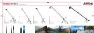
HandyMan G-Force PRO Manual eng Apr07 - ABC Products
HandyMan G-Force PRO Manual eng Apr07 - ABC Products
HandyMan G-Force PRO Manual eng Apr07 - ABC Products

You also want an ePaper? Increase the reach of your titles
YUMPU automatically turns print PDFs into web optimized ePapers that Google loves.
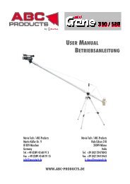
www.abc-products.de<br />
e-mail: info@movietech.de<br />
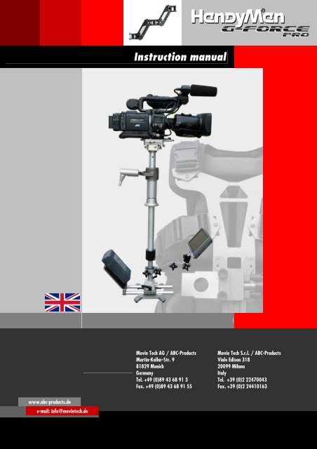
Instruction manual<br />
Movie Tech AG / <strong>ABC</strong>-<strong>Products</strong><br />
Martin-Kollar-Str. 9<br />
81829 Munich<br />
Germany<br />
Tel. +49 (0)89 43 68 91 3<br />
Fax. +49 (0)89 43 68 91 55<br />
Movie Tech S.r.l. / <strong>ABC</strong>-<strong>Products</strong><br />
Viale Edison 318<br />
20099 Milano<br />
Italy<br />
Tel. +39 (0)2 22470043<br />
Fax. +39 (0)2 24410163
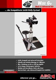
Welcome to <strong>ABC</strong>-<strong>Products</strong><br />
Our vision ist to help our customers achieve the moving shot with any type of<br />
camera in any situation. This is a chall<strong>eng</strong>e that we are pleased to pursue and<br />
that we can only master with constant feedback from our customers.<br />
We wish you great pleasure using our products.
Overview<br />
APR07<br />
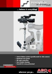
We congratulate you on your purchase of the <strong>HandyMan</strong> G-<strong>Force</strong> pro.<br />
It was specifically developed for demanding users. Without compromise in every detail, the G-<strong>Force</strong> is particularly<br />
well-suited for use in the area of MiniDV, DV and HD(V) camcorders.<br />
The <strong>HandyMan</strong> G-<strong>Force</strong> integrates seamlessly into the comprehensive <strong>ABC</strong> assortment and can be combined with<br />
components of existing products.<br />
Adjustable post<br />
With the precision mechanism, the side-to-side module can be<br />
continuously adjusted in two axes. A stop module provides the<br />
necessary security for the camera.<br />
The power supply makes it possible to use various auxiliary devices<br />
such as camera lights. Three BNC connections make it possible to<br />
connect an HD monitor (optional).<br />
Spring arm<br />
Two independent spring systems perfectly balance the movements of<br />
the operator. The lightweight design and extremely compact dimensions<br />
of the spring arm are impressive and ensure the desired<br />
maneuverability.<br />
And, the spring tension can be steplessly adjusted.<br />
Vest<br />
The completely redesigned G-<strong>Force</strong> vest defines new standards. The<br />
light, but torsion-resistant aluminum plate can be fitted to nearly any body size. Chest and shoulder belts can be<br />
variably adjusted in the position. The spring arm mount can be moved up or down.<br />
The multi-part pad elements can be individually positioned and are washable. A double aluminum profile in S shape,<br />
which can also be fitted in the back, ensures that loads on the spinal column are properly distributed. And, air ducts<br />
make wearing the vest noticeably more comfortable.<br />
www.abc-products.de … wherever you go 3
Contents (English)<br />
APR07<br />
Overview ..................................................................................................................................................................... 3<br />
Contents (English) ........................................................................................................................................................ 4<br />
Package contents ......................................................................................................................................................... 5<br />
Overview of the G-<strong>Force</strong> pro sled.................................................................................................................................. 7<br />
Overview of the G-<strong>Force</strong> pro vest.................................................................................................................................. 8<br />
Overview of the G-<strong>Force</strong> pro connections ...................................................................................................................... 9<br />
Overview of the G-<strong>Force</strong> pro monitor.......................................................................................................................... 10<br />
<strong>HandyMan</strong>: G-<strong>Force</strong> Pro ............................................................................................................................................. 11<br />
General safety instructions: ................................................................................................................................... 11<br />
Technical data:...................................................................................................................................................... 12<br />
Installation and mounting .......................................................................................................................................... 13<br />
Setting up the trim tripod with trim plate ............................................................................................................... 13<br />
Mounting the monitor on the monitor holder ......................................................................................................... 15<br />
Mounting the monitor holder with monitor on the post........................................................................................... 15<br />
Mounting the battery ............................................................................................................................................ 15<br />
Mounting the camcorder........................................................................................................................................ 15<br />
Mounting the camcorder........................................................................................................................................ 16<br />
Trimming the system.................................................................................................................................................. 17<br />
Swinging the sled.................................................................................................................................................. 18<br />
Putting on the vest................................................................................................................................................ 19<br />
Setting the height adjustment for the spring arm / changing the left/right sled guide............................................. 21<br />
Setting the adjustment angle................................................................................................................................. 21<br />
Mounting the spring arm....................................................................................................................................... 22<br />
Mounting the sled to the spring arm ...................................................................................................................... 23<br />
Hand posture and guiding the sled ........................................................................................................................ 23<br />
Adjusting the spring arm ....................................................................................................................................... 24<br />
Testing the trimming ............................................................................................................................................. 24<br />
Low mode............................................................................................................................................................. 25<br />
Mounting the "Hoodman" anti-glare device............................................................................................................ 26<br />
Optional accessories ................................................................................................................................................... 27<br />
Mounting the bubble level, item no. 821497 ......................................................................................................... 27<br />
Mounting the digital voltage indicator, item no. 821481........................................................................................ 27<br />
Sandbag for weighting the tripod, item no. 832100............................................................................................... 27<br />
www.abc-products.de … wherever you go 4
Package contents<br />
Carrying case with internal divider<br />
G-<strong>Force</strong> vest Pro, 2-part<br />
Head module with video-in<br />
3x BNC / power out (full battery<br />
voltage unregulated)<br />
Battery adapter plate V-Mount with<br />
telescope sled/clamp and angle<br />
adjustment<br />
Adjustable carrying belt with<br />
padding<br />
Two Allen keys<br />
Size 4.0 (for adjusting the telescope and<br />
trim post and adjusting the angle of the<br />
battery adapter)<br />
Size 3.0 (for adjusting the aluminum parts<br />
on the vest)<br />
Video cable BNC on cinch (75 Ohm)<br />
2-axis adjusting mechanism for<br />
trimming the camera (side to side<br />
module)<br />
Foot module: Video-out 3x BNC<br />
APR07<br />
Trim tripod with 2 telescopes and<br />
16 mm (0.63 in.) connection pin<br />
Monitor holder, 5 part / with<br />
spherical head<br />
Wedge plate (mounting stage)<br />
Foot module, back: Fischer<br />
connections and ON/OFF switch<br />
Accessory case with velcro<br />
connection, German/English/Italian<br />
instruction manual, checklist/<br />
accessory catalog<br />
Trim tube / sled, G-<strong>Force</strong> Pro<br />
Gimbal with gimbal clamp, toolless<br />
rotary clamping system<br />
Trim plate for set-up on the tripod<br />
www.abc-products.de … wherever you go 5
Stand with rubber feet<br />
A) Monitor<br />
B) Monitor case<br />
C) Anti-glare device ("Hoodman")<br />
G-<strong>Force</strong> double spring arm Scale for the travel of the spring<br />
arm<br />
(0 = low pretension with low camera weight)<br />
(3 = high pretension with high camera<br />
weight)<br />
APR07<br />
Monitor video power cable<br />
(MiniDin 6-pin to Fischer 4-pin)<br />
www.abc-products.de … wherever you go 6
APR07<br />
Overview of the G-<strong>Force</strong> pro sled<br />
Fine leveling control for perfect<br />
taring in the<br />
side-to-side module<br />
Traverse sled with safety<br />
function<br />
Large diameter hand grip<br />
for precise control<br />
7"- TFT LCD monitor<br />
(16:9/4:3, Pal/NTSC)<br />
DC 12 V power cable<br />
Spherical head for turning the<br />
monitor 360 degrees / easy low<br />
mode<br />
Multi-variable monitor holder with<br />
toolless adjustment for universal<br />
positioning<br />
Stepless battery adjustment (toolless) - for<br />
extremely compact size of the system<br />
Horizontal travel of max. 185 mm (7.28 in.)<br />
Toolless clamping system<br />
on the gimbal for quick<br />
set-up<br />
Connection sockets:<br />
1 x video + power out 12 Volt<br />
3 x BNC for HD<br />
1 x power out<br />
1 x power in<br />
Connection sockets<br />
3 x BNC in for HD<br />
1 x power out<br />
Precision ball bearing<br />
Ergonomic design supports the vertical<br />
swivel movements<br />
Telescopic post - system l<strong>eng</strong>th up to 340 mm<br />
(13.39 in.)<br />
Adjustable battery holder<br />
angle 180 degrees for<br />
Sony V-Mount<br />
Optional: Anton Bauer<br />
NP 1<br />
& voltage indicator<br />
Base plate with various mounting threads<br />
and stable jack stands<br />
www.abc-products.de … wherever you go 7
APR07<br />
Overview of the G-<strong>Force</strong> pro vest<br />
High-str<strong>eng</strong>th clasps, durable,<br />
resistant to deformation<br />
Adjustment function for<br />
perfect shoulder width<br />
adjustment<br />
L<strong>eng</strong>th of the fastening belts<br />
can be flexibly adjusted<br />
Mount for double<br />
spring arm, made<br />
of steel<br />
Travel for spring<br />
arm angle<br />
+/- 20 degrees<br />
S-Ergotech<br />
Aluminum back shaping<br />
in S form for perfect<br />
spinal column support<br />
function<br />
Tough Cordura material<br />
Best fit<br />
Interior padding can be<br />
individually fitted to the body<br />
Adjustment function for<br />
perfect chest belt<br />
adjustment<br />
Adjustable front plate<br />
for l<strong>eng</strong>th adjustment,<br />
travel up to 70 mm<br />
(2.76 in.)<br />
Air-System-Pro<br />
Padding with air<br />
ducts for optimal<br />
comfort<br />
Stepless height adjustment of<br />
the spring arm, travel: 160<br />
mm (6.30 in.)<br />
www.abc-products.de … wherever you go 8
APR07<br />
Overview of the G-<strong>Force</strong> pro connections<br />
Head module: Video-in 3x BNC<br />
Lateral power out (full battery voltage unregulated)<br />
Connection for XLR to 2-pin Fischer via spiral cable to<br />
external power supply from camcorders or similar (max.<br />
25 watt)<br />
Foot module: Video-out 3x BNC<br />
A) Fischer 4-pin jack 12V, regulated (deactivatable)<br />
B) Power in/out Fischer, 2-pin (battery voltage)<br />
C) and B) Connection options for battery current supply or<br />
LCD voltage indicator (see Accessories)<br />
D) Main power on/off switch<br />
www.abc-products.de … wherever you go 9
APR07<br />
Overview of the G-<strong>Force</strong> pro monitor<br />
Menu buttons<br />
Power button and<br />
power LED<br />
Format switch<br />
(4:3 or 16:9)<br />
Mirror function Video source<br />
toggle switch<br />
To call up the menu and to make any changes, press the Menu<br />
button and navigate to the desired sub-menu by using the -/+<br />
buttons. Press the Menu button to activate your selection. See an<br />
overview of possible sub-menus in the graphic to the left.<br />
Technical data:<br />
Screen size: 7" (17.78 cm)<br />
Display format: 16:9<br />
Power consumption: 8.5 watt<br />
Power supply: DC 12 Volt<br />
Brightness: 300 nits<br />
System: PAL/NTSC<br />
Resolution: 480 x 234<br />
Operating temperature: 0 ° to approx. 50 °C (32 ° to approx. 122 °F)<br />
Ext. audio/video<br />
input, headphone<br />
output<br />
(ext. wired only)<br />
www.abc-products.de … wherever you go 10
<strong>HandyMan</strong>: G-<strong>Force</strong> Pro<br />
General safety instructions:<br />
APR07<br />
1) Set up the trim tripod on a solid surface and secure with sandbags if necessary.<br />
2) Using the fixing screw, secure the camera base plate to the camcorder.<br />
3) Mount the camera wedge plate true to side - it can otherwise lead to gear rack damage.<br />
4) During each trim procedure, open the bleeder screws, trim the tripod, secure the bleeder screws.<br />
5) Operating the device stresses the muscles of the back among other things. Please allow for sufficient recovery<br />
time between uses.<br />
6) Prevent water from penetrating the device.<br />
7) When opening the gimbal clamp to adjust the height of the gimbal on the top tube, the trim tube must be<br />
secured against slipping through uncontrolled.<br />
8) Re-tighten the gimbal clamp applying moderate force after adjusting the gimbal.<br />
9) Using moderate force only, tighten the Allen screw of the telescope clamp until the clamping force is light, but<br />
sufficient.<br />
10) Using an Allen key, secure the rig against slipping out of the trim plate.<br />
11) Turn the telescope (bottom pipe) max. 360 degrees to avoid damaging the enclosed cables.<br />
12) The plug-in connectors must be smooth – if there is any resistance, please note the correct mark position of the<br />
plugs.<br />
13) Loosen the plugs by pulling the plug case only – do not use a rotary motion to loosen the plugs.<br />
14) When oscillating to establish the center of gravity, do not hit the rig against the trim tripod to avoid damage.<br />
www.abc-products.de … wherever you go 11
Technical data:<br />
APR07<br />
Sled<br />
Full weight of the sled incl. monitor holder: 3.65 kg (8.05 lbs)<br />
Travel of gimbal top pipe: 250 mm (9.84 in.)<br />
Telescopic post: max. 350 mm (13.78 in.)<br />
Forward travel of battery holder: 75 mm (2.95 in.)<br />
Battery holder adjustment angle: 180°<br />
Monitor holder l<strong>eng</strong>th: max. 220 mm (13.78 in.)<br />
Path for height adjustment of the spring arm<br />
on the vest adjusting mechanism: 160 mm (2.95 in.)<br />
Wedge plate l<strong>eng</strong>th: 150 mm (2.95 in.)<br />
Spring arm<br />
Weight of the spring arm, G-<strong>Force</strong> Pro DV/HDV: 2.5 kg (5.51 lbs)<br />
Spring arm max. load, G-<strong>Force</strong> Pro DV/HDV (camcorder): 5.00 kg (11.02 lbs)<br />
Vest<br />
Weight: 2.60 g (5.73 lbs)<br />
Monitor G-<strong>Force</strong> Pro TFT 7 inch<br />
Size of screen diagonal: 175 mm (7 in.)<br />
Power supply: 12 V<br />
Weight: 400 g (0.88 lbs)<br />
Format 4:3 / 16:9 selectable<br />
Mirror function - Image can be displayed horizontally or vertically<br />
Tripod<br />
Weight: 4.20 kg (9.26 lbs)<br />
Max. extension: 1760 mm (69.29 in.)<br />
Min. extension: 840 mm (33.07 in.)<br />
Trim plate l<strong>eng</strong>th: 280 mm (11.02 in.)<br />
www.abc-products.de … wherever you go 12
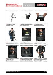
Installation and mounting<br />
Setting up the trim tripod with trim plate<br />
APR07<br />
Open the screw plug (Fig. 1) of the foot clamp. Pull the top foot back approx. 180 degrees until it reaches a point of<br />
<strong>eng</strong>agement. Open the other two tripod feet as shown until they form a safe triangle base. Then close the safety screw.<br />
Make sure that the base is level and solid to ensure safe system conditions under load.<br />
Fig. 1<br />
Fig. 2<br />
Mount the system trim plate as shown (Fig. 5 - Fig. 8) and securely re-tighten the safety screw. Hang the included Allen<br />
keys in the intended holes.<br />
Fig. 5<br />
Fig. 6<br />
The ideal telescope work height of the tripod is about between your shoulders and your elbows (see Fig. 6). The tripod<br />
becomes unstable if the telescope is too high. Under high loads (heavy camcorder), decrease the height of the telescope<br />
appropriately. To increase the protection against inadvertent tipping, we recommend you weigh down the tripod legs<br />
with a sandbag or similar.<br />
When doing so, make sure that the black plastic sleeve for the gimbal mount is positioned over the long tripod foot for a<br />
more stable base when trimming.<br />
Fig. 9<br />
www.abc-products.de … wherever you go 13<br />
Fig. 3<br />
Fig. 7<br />
Pull the camera base plate for mounting the camera from the trim module (side-to-side<br />
module). To do so, press the side safety button (Fig. 9).<br />
Fig. 4<br />
Fig. 8<br />
Position 2:<br />
Trim position<br />
Position 1:<br />
Stand-by position
Hang the trim tube (sled) in the trim plate on position 1 (stand-by<br />
position, Fig. 10). Secure the trim tube (sled) using the included Allen<br />
key (Fig. 11).<br />
Guidelines:<br />
APR07<br />
� The gimbal forms the center point of the axis between the camera and the stand. Similar to a traditional scale,<br />
it is necessary to change the weight between the camera and the stand. The monitor used (depending on type<br />
with or without flange-mounted battery), the battery and, depending on design, the single or double battery<br />
holder plate for the monitor power supply are used as counterweight for camera stabilization.<br />
The desired counterweight for gliding movements can be obtained by the factors of vertical telescopic extension<br />
= shifting of the battery weight up (toward the gimbal or down away from the gimbal) and horizontal<br />
adjustment of the battery toward or away from the post.<br />
� If the camera is heavy compared to the base weight, it does not stay in the desired, vertical or upright position.<br />
� If the ratio between the camera and base weight weighs out neutral, the system must be controlled very<br />
delicately. The slightest contact causes a reaction.<br />
� A slight bottom heaviness should therefore be achieved when trimming and variably adjusted depending on<br />
personal preference and experience.<br />
� If too heavy, it brings increased mass to one side (base weight) into the movement and leads to unwanted<br />
rocking movements.<br />
� The following factors are used to determine the weight required to balance the camera:<br />
o Extraction of the lower telescope (travel max. 35 cm / 1.378 in.) (Fig. 12)<br />
o Horizontal extraction of the battery with traverse sled (Fig. 13)<br />
o Stepless angle / weight adjustment of the battery (Fig. 14)<br />
o Position of the gimbal on the post<br />
Fig. 12<br />
Fig. 13<br />
� A shorter horizontal extraction of the battery (Fig. 14) keeps the system compact, increases maneuverability<br />
and offers protection against bothersome leg contact.<br />
www.abc-products.de … wherever you go 14<br />
Fig. 10<br />
Fig. 14<br />
Fig. 11
Mounting the monitor on the monitor holder<br />
APR07<br />
The movable thread for mounting on the spherical head of the monitor holder is on the back of the monitor. Turn the<br />
screw of the spherical head into the thread of the monitor until it lightly touches the screw of the monitor housing. Then<br />
secure the screw with the black nut of the spherical head.<br />
Fig. 16<br />
Fig. 17<br />
Mounting the monitor holder with monitor on the post<br />
Remove the clamping screw of the monitor holder for mounting on the post (Fig. 20).<br />
Plastic reducer<br />
You can attach the monitor holder to the lower post at variable heights with the inserted<br />
plastic reducer. If you want to attach the monitor holder to the top pipe, remove the<br />
plastic insert (Fig. 19).<br />
Press the clamping system over the post and using the clamping screw secure the holder.<br />
Make sure the position is parallel to the post axis.<br />
Connect the monitor cable to the included video power cable (MiniDIN 6-pin). When connecting the cables,<br />
please note the marks above. Then connect the video power cable to the current module (Fischer 4-pin) (Fig. 23).<br />
Fig. 20<br />
Mounting the battery<br />
Fig. 21<br />
www.abc-products.de … wherever you go 15<br />
Fig. 22<br />
Push the battery (V-Mount) from above into the adapter plate until it securely <strong>eng</strong>ages.<br />
Fig. 24<br />
Fig. 18<br />
Fig. 23<br />
Clamping screw<br />
Fig. 19
Mounting the camcorder<br />
APR07<br />
Prepare the camcorder for use. Insert the tape and attach the battery (12V camcorder power supply via XLS cable if<br />
necessary). Attach the microphone (also secure to prevent slipping, since it can affect trimming) or remove it. Position<br />
your camera's viewfinder as desired or remove the viewfinder for large camcorders if necessary for reasons of weight.<br />
Please secure any loose cables against slipping.<br />
Mount the wedge plate of the sliding unit to the underside of the camcorder using the<br />
included screws 1/4 inch or 3/8 inch depending on thread on the camera. Depending<br />
on the camcorder, the pin for locking the camera (DV/HDV camcorder) can be<br />
removed by unscrewing it.<br />
For stability reasons, mount an appropriate camera base plate (tripod plate) to the<br />
system wedge plate for larger camcorders.<br />
Important!<br />
Fig. 26<br />
� Make sure that the gear guide is on the left side when mounting in the<br />
direction of the objective. (Fig. 27)<br />
� Open the brake (marked red) of the vertical slide direction and push the wedge plate with camcorder in the<br />
traverse sled into a more secure balanced initial position. (Fig. 28 & 29)<br />
� Close the bleeder screw securely! (Please open the brake with each trim change and then securely close again!)<br />
� Connect the video cable (included) to the BNC plug on the BNC jack of the video/current module/system<br />
identified with a black ring and your camcorder. (Depending on your camcorder's connection, a cinch or BNC<br />
plug may be required.) Note the included BNC adapter.<br />
� If necessary, connect the XLR/Fisher cable to the power supply of 12V camcorders on the video out of the<br />
video/current module.<br />
Fig. 27<br />
Fig. 30<br />
Fig. 28<br />
www.abc-products.de … wherever you go 16<br />
Fig. 31<br />
Fig. 29<br />
Fig. 25
Trimming the system<br />
APR07<br />
Position change / hanging the sled on the trim plate<br />
Fig. 32<br />
Basic setting<br />
Hang the sled for trimming in the gimbal mount<br />
(position 2: trim position).<br />
Bring the monitor into the desired viewing position. Note the height and angle adjustment options. If required for<br />
rotation, you can now mount the anti-glare device (see page 19). Open the gimbal clamping system (Fig. 25) using a<br />
rotary motion. Push the post into the desired position (here the mount height is crucial). Close the clamping system<br />
again.<br />
Fig. 34<br />
Fig. 35<br />
www.abc-products.de … wherever you go 17<br />
Fig. 36<br />
Correct the counterweight until there is a slight bottom heaviness by:<br />
� Opening the telescopic clamp, extend or retract telescope (Fig. 37)<br />
� Horizontal extraction of the battery (extend or retract telescope) (Fig. 38)<br />
� Angle adjustment of the battery on the rotary joint (Fig. 39)<br />
Fig. 37<br />
Fig. 33<br />
Fig. 38<br />
Fig. 39
APR07<br />
Optimize the trimming by adjusting the camera in the horizontal and vertical direction on the camera sled/side-to-side<br />
module. Open the brakes and correct the balance by turning the "gray" screws. Always secure the brakes again<br />
afterwards.<br />
(an optional bubble level can be helpful when balancing, item no. 821497)<br />
Fig. 40<br />
Fig. 41<br />
Optional accessory: bubble level<br />
Optimize the trimming for horizontal panning:<br />
The correction is like "balancing a car tire" to make sure it runs as round as possible.<br />
A system balanced horizontally and vertically makes smooth, "floating" movements and balanced panning possible.<br />
Now bring the sled into a horizontal position again. "Roll" the sled around its own axis. If the sled is not "running<br />
smoothly", please correct this on the position at which the imbalance becomes evident, e.g. by correcting the angle of the<br />
battery plate or correcting the extension of the battery plate.<br />
Additional corrections can be carried out if necessary by "fine trimming" on the camera sled / side-to-side module.<br />
Fig. 42<br />
Swinging the sled<br />
Fig. 43<br />
Lift the sled approx. 80-90 degrees (travel movement). Let the system swing. If the system swings too quickly, the<br />
bottom heaviness may be too high. 2-3 seconds (counting 21, 22, etc.) on average means a good balance.<br />
Be careful when carrying out the initial swinging motion – make sure that the system can swing through parallel and<br />
does not swing directed against the tripod, which could otherwise damage the monitor.<br />
Also make sure that the stability of the tripod is secured.<br />
www.abc-products.de … wherever you go 18<br />
Fig. 44
APR07<br />
The system should not turn off during the swinging motion. Otherwise, the system should be re-trimmed horizontally on<br />
the side-to-side module.<br />
Fig. 45<br />
Fig. 46<br />
Turn on the main switch on the bottom voltage module. (A digital voltage indicator that gives information about the<br />
charging condition of the battery is optional, item no. 821481)<br />
Also turn on the camera and monitor. Check whether the monitor receives a picture signal.<br />
Fig. 46<br />
Putting on the vest<br />
Fig. 47<br />
www.abc-products.de … wherever you go 19<br />
Fig. 47<br />
Optional accessory: voltage indicator<br />
Open the vest by pressing the snap connector on one side only. The metal plate must be in the front. Slide an arm<br />
through the respective opening and close the chest and lap belts.<br />
Fig. 48<br />
Fig. 49<br />
Fig. 50<br />
Fig. 51
APR07<br />
The front plate of the vest should be worn on the center axis in front of the body. Then tighten the belts for individual<br />
areas; the system should be comfortable for you to wear. If the front plate is adjusted too long, you can shorten the<br />
front plate by opening, moving and closing the screws.<br />
Fig. 52<br />
The l<strong>eng</strong>th of the shoulder pad can be adjusted or corrected by moving the velcro straps or variable pull straps. The width<br />
of the shoulder pad can also be set by opening, moving and closing the metal parts. Allen key no. 3.0 is required.<br />
The same also applies to the height of the chest pad, which can be adjusted like the shoulder pad. Allen key no. 3.0 is<br />
also required.<br />
Make sure that you can work with your thighs and arms freely (Fig. 56). You can determine the optimal vest position<br />
just by experience. There are no rigid guidelines (with or without hip contact).<br />
The vest should sit firmly so that you feel clear contact with the S-shaped back protector.<br />
All interior parts of the vest have velcro connections and can be individually positioned according to your wishes.<br />
Fig. 55<br />
Fig. 53<br />
Fig. 56<br />
www.abc-products.de … wherever you go 20<br />
Fig. 54
APR07<br />
Setting the height adjustment for the spring arm /<br />
changing the left/right sled guide<br />
The element for mounting the spring arm can be mounted for left or right-bearing operators. To switch the position,<br />
open both smaller clamping levers (Fig. 57). Pull the mount out of the guide completely and turn it 180 degrees<br />
(Fig. 58 & 59).<br />
Re-attach the sled to the guide and adjust to the desired height by closing the clamping lever. Your preference for the<br />
post guide is crucial for the carrying position. Just try both variants.<br />
Fig. 57<br />
Fig. 58<br />
Setting the adjustment angle<br />
Fig. 59<br />
The assembly unit also has a stepless angle adjustment option for the spring arm with -20 to +20 degrees of travel. This<br />
adjustment makes system balance possible depending on your natural body posture and shape or the task.<br />
Generally, an angle adjustment of up to 10-15 degrees to the rear is desired, i.e. raising the mounted spring arm. If the<br />
angle points too far forward, the system moves strongly away from the body and too much effort is expended to<br />
counteract the movement. If the angle points too far back, the system moves toward the body appropriately.<br />
The goal is to achieve a neutral angle position in which a natural, straight posture can be maintained and the system can<br />
be guided "near the body" without exertion. Freehand balance exercises show you the correction requirement.<br />
Fig. 61<br />
www.abc-products.de … wherever you go 21<br />
Fig. 60<br />
Open the large clamping lever (Fig. 61). You can move the lever by pulling it and re<strong>eng</strong>aging<br />
it in position.
APR07<br />
The screws for the angle adjustment are of varying l<strong>eng</strong>ths (Fig. 62). To adjust the angle toward the body, the long screw<br />
must be moved up.<br />
Adjust the angle as desired by tightening the top screw. You can then counter using the bottom screw. Then close the<br />
large clamping lever (opposite direction than as shown in Fig. 61). The angle mount should now fit again without any<br />
gap.<br />
Fig. 62<br />
Mounting the spring arm<br />
Fig. 63<br />
Pull out the safety pin from the mount by pressing on the head of the pin. Guide the spring arm with the U-shaped<br />
mount over the angle mount. Line up the holes (Fig. 67) and secure the units by sliding in the safety pin until it <strong>eng</strong>ages<br />
(Fig. 68).<br />
Balance the spring arm in front of your body by moving the arm toward the front/back or left and right. Always return<br />
to a resting middle position.<br />
Mount or install the spring arm in the stand-by position in the tripod plate. If you still have the sled in the trim position,<br />
please relocate it.<br />
Fig. 66<br />
Fig. 67<br />
www.abc-products.de … wherever you go 22<br />
Fig. 68<br />
Fig. 64<br />
Fig. 69<br />
Fig. 65
Mounting the sled to the spring arm<br />
APR07<br />
Remove the safety screw from the tripod plate and park it in the intended mount.<br />
Move one step forward and to the knees under the gimbal and connect the gimbal pin to the mount.<br />
Tighten your stomach and back muscles and straighten up together with the sled safely and slowly.<br />
Guide the system out of the mount and put yourself into a relaxed upright position.<br />
Fig. 70<br />
Fig. 71<br />
Start with balancing exercises in which you find the ideal point at which the system easily moves and rests in front of<br />
your body. Once you have found this position, you can carefully attempt balancing exercises without your hands. Always<br />
feel your way to this ideal position with the sled locked.<br />
The goal is to get a feel for the interaction of your posture and weight with the collective behavior of the system. Guide<br />
the system with a "sensitive hand", i.e. without transferring force to the sled.<br />
It is enough to feel the grip or material. Only light pulses are required to bring the camera into the desired position.<br />
Hand posture and guiding the sled<br />
Fig. 72<br />
Fig. 73<br />
www.abc-products.de … wherever you go 23<br />
Fig. 72<br />
Hold the panning hand as close to the joint as possible. The further away the hand is<br />
from the gimbal, the stronger the effect pulse from the higher angle of deflection.<br />
The second hand (guide hand) rests on the connection piece to the gimbal. Press and<br />
pull the spring arm up and down to change the height of the rotational position.<br />
Fig. 74<br />
Fig. 75
Adjusting the spring arm<br />
APR07<br />
Each of the spring arm sections is equipped with two spring elements, whose pretension can be adjusted according to the<br />
weight of the camera. The Allen key 4.0 is required (Fig. 73). If the pretension is too high, the spring elements may not<br />
absorb the body's movements sufficiently.<br />
If the pretension is too low, movement spreads through the arm or much effort is required to hold the arm. The tension<br />
should be set so that the absorption range/spring travel is balanced up and down.<br />
Always correct the tension of the spring elements without load – and make sure that the tension on both springs is<br />
always adjusted synchronously for each segment.<br />
Fig. 76<br />
Fig. 77<br />
Start with a pretension in which both elements are close to parallel under load. Then test and correct the pretension.<br />
Frequently, the front spring element easily faces upwards, the rear runs parallel.<br />
(Fig. 80)<br />
Testing the trimming<br />
Quickly push and pull the system forward and backward, parallel with guide hand. If the system is correctly balanced –<br />
holds the position – there is no swinging motion (base too firm) and no rotation (side to side, left or right).<br />
Fig. 80<br />
Fig. 81<br />
Also go around the system. Hold the sled with your guide hand only. The sled should stay in the middle.<br />
www.abc-products.de … wherever you go 24<br />
Fig. 78<br />
Fig. 82<br />
Fig. 79<br />
Fig. 83
Fig. 84<br />
Low mode<br />
Fig. 85<br />
APR07<br />
Open the clamping system of the gimbal and standing on its head lower the camera as desired. Then secure and close the<br />
clamping system, open the telescope and pull it up as far as you need to counterweight the camera.<br />
Now, mount the monitor turned 180 degrees at the desired position, hang the sled into the trim position and carry out<br />
any fine trimming using the weight extension on the post and side-to-side module.<br />
You must then flip the monitor picture 180 degrees (Fig. 80 or page 8). The picture must be flipped again later. Re-hang<br />
the sled in the stand-by position and mount again with the spring arm.<br />
Fig. 88<br />
Fig. 89<br />
www.abc-products.de … wherever you go 25<br />
Fig. 86<br />
Fig. 90<br />
Fig. 87<br />
Fig. 91
Mounting the "Hoodman" anti-glare device<br />
APR07<br />
Measure the top edge of the monitor housing (possibly mark the area to evenly affix the velcro strip). Then remove the<br />
protective film on the bottom of the velcro strip and attach the velcro evenly. Using the velcro fastener, mount the antiglare<br />
device in the desired position.<br />
Fig. 92<br />
Fig. 93<br />
www.abc-products.de … wherever you go 26<br />
Fig. 94
Optional accessories<br />
Mounting the bubble level, item no. 821497<br />
APR07<br />
Loosen the fixing screw for the bubble level and from the front, push onto the tubes of<br />
the battery sliding unit. Close the safety screw. The system must be re-balanced<br />
accordingly.<br />
Fig. 95<br />
Mounting the digital voltage indicator, item no. 821481<br />
Screw the voltage indicator onto the foot plate. A coin or screwdriver is required.<br />
Attach the connection cable to the power supply middle connection.<br />
Fig. 96<br />
Sandbag for weighting the tripod, item no. 832100<br />
A sandbag can also be attached to the tripod to improve its stability.<br />
Fig. 97<br />
<strong>ABC</strong>-<strong>Products</strong> regularly offers workshops on operating the <strong>HandyMan</strong> G-<strong>Force</strong>.<br />
Simply request current workshop dates (info@movietech.de).<br />
www.abc-products.de … wherever you go 27
Under the roof of …<br />
Movie Tech AG, located in Munich, is one of the leading manufactures of<br />
products and solutions for the film industry. The product line of Movie Tech<br />
AG includes the hole range of camera cranes, dollys, light systems, remote<br />
heads and related accessories. Movie Tech AG purpose is to build professional<br />
film equipment to make the work for film teams on the set or in the<br />
studios easier. In order to fulfill customer's requests better, Movie Tech AG<br />
has branches in the U.S. and Italy.<br />
Movie Tech AG acquired the company <strong>ABC</strong>-<strong>Products</strong> in January<br />
2000 with the objective to improve the development in the<br />
broadcast market. <strong>ABC</strong>-<strong>Products</strong> is today one of leading brands<br />
in the area of extremely light and high-grade broadcast equipment.<br />
Since 2006, MTS equipment has been added to the portfolio of MovieTech<br />
AG. MTS - Media Technical Systems - manufactures premium studio equipment,<br />
including droparms, pantographs, lighting hoists, and telescopes.<br />
MovieTech AG<br />
Martin-Kollar-Str. 9 · 81829 München · Germany<br />
Tel. +49/89-4368913 · Fax +49/89-43689155<br />
e-mail: info@movietech.de · www.movietech.de www.movietech.de