DXV35-DT3-LX 0611.pdf - Mendota
DXV35-DT3-LX 0611.pdf - Mendota
DXV35-DT3-LX 0611.pdf - Mendota
- No tags were found...

Create successful ePaper yourself
Turn your PDF publications into a flip-book with our unique Google optimized e-Paper software.
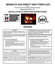
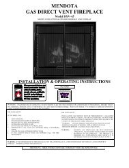
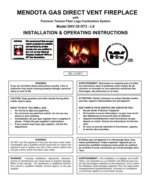
MENDOTA GAS DIRECT VENT FIREPLACEwithPremium Texture Fiber Logs Combustion SystemModel DXV-35 <strong>DT3</strong> - <strong>LX</strong>INSTALLATION & OPERATING INSTRUCTIONSNO. <strong>LX</strong>-0611WARNINGIf you do not follow these instructions exactly, a fire orexplosion may result causing property damage, personalinjury or loss of life.AVERTISSEMENT. Quiconque ne respecte pas à la lettreles instructions dans la présente notice risque de déclencherun incendie ou une explosion entraînant desdommages, des blessures ou la mort.CAUTION: Keep gasoline and other liquids having flammablevapors away.ATTENTION. Garder l’essence ou autres liquides produisantdes vapeurs inflammables loin del’appareil.WHAT TO DO IF YOU SMELL GAS Do not try to light any appliance. Do not touch any electrical switch; do not use anyphone in your building. Immediately call your gas supplier from a neighbor'sphone. Follow the gas supplier’s instructions. If you cannot reach your gas supplier, call the firedepartment.QUE FAIRE SI VOUS SENTEZ UNE ODEUR DE GAZ : Ne pas tenter d’allumer d’appareil. Ne touchez à aucun interrupteur; ne pas vous servirdes téléphones se trouvant dans le bâtiment. Appelez immédiatement votre fournisseur de gazdepuis un voisin. Suivez les instructions du fournisseur. Si vous ne pouvez rejoindre le fournisseur, appelezle service des incendies.WARNINGDo NOT use this appliance if any part has been under water.Immediately call a qualified service technician to inspect theappliance and to replace any part of the control system andany gas control, which has been under water.N’utilisez pas cet appareil s’il a été plongé dans l’eau,même partiellement. Faites inspecter l’appareil par untechnicien qualifiéet remplacez toute partie du systèmede contrôle et toute commande qui ont été plongés dansl’eau.WARNING: Improper installation, adjustment, alteration,service or maintenance can cause injury or property damage.Refer to this manual. For assistance or additional informationconsult a qualified installer, service agency or the gassupplier.AVERTISSEMENT : Une installation, un réglage, une modification,une réparation ou un entretien mal effectué peut causerdes dommages matériels ou des blessures. Voir la noticede l'utilisateur quiaccompgne l’appareil. Pour de l’aide ouedsrenseignements supplémentaires, consultez un installateur,un technicien agréé ou le fournisseur de gaz.
FOR YOUR SAFETY READ BEFORE LIGHTINGPOUR PLUS DE SÉCURITÉ, LIRE AVANTD'ALLUMERWARNINGDo not operate this appliance with the glass removed,cracked or broken. A licensed or qualified personshould do replacement of glass.Attention. Ne pas utiliser l’appareil si le panneau frontalen verre n’est pas enplace, est craqué ou brisé.Confiez leremplacement du panneau à untechnicienagréé.WAWAThis appliance must be installed in accordance withlocal codes, if any; if none, follow the National FuelGas Code, ANSI Z223.1, or Canadian InstallationCodes, CAN/CGA-B149. Gas and Propane InstallationCode, CSA B149.1Installer l'appareil selon les codes ou règlements locaux,ou, en l'absence dételés règlements, selon lescodes d'installation ANSI Z223.1, National Fuel GasCode ou CAN/CGA-B149 en vigueur.This appliance is only for use with the type(s) of gasindicated on the rating plate and may be installed inan aftermarket, permanently located, manufacturedhome (USA only) or mobile home, where not prohibitedby local codes. See owner's manual for details.This appliance is supplied with a conversion kit.Cet appareil doit être utilisé uniquement avec le typede gaz indiqué sur la plaque signalétique. Cet appareilpeut être installé dans une maison préfabriquée oumobile (É.-U. seulement) installée à demeure si lesrèglements locaux le permettent. Voir la notice del'utilisateur pour plus de renseignements. Cet appareilne peut pas être utilisé avecd'autres gaz sauf si unetrousse deconversion certifiée est fournie.Caution: Label all wires prior to disconnectionwhen servicing controls. Wiring errors can causeimproper and dangerous operation.In the Commonwealth of Massachusetts: Installation must be performed by a licensedplumber or gas fitter; A CO detector shall be installed in the roomwhere the appliance is installed.Attention. Au moment de l’entretiennes commandes,étiquetez tous les fil savant de les débrancher.Des erreurs decâblage peuvententraîner unfonctionnement inadéquat etdangereux.CAUTIONTHESE INSTRUCTIONS ARE TO REMAIN WITHTHE HOMEOWNER.
<strong>DXV35</strong> <strong>DT3</strong> FEATURES - QUICK REFERENCE INFORMATIONEXTERNAL DIMENSIONS: 35-7/8” Wide X 31-1/2” High X 15-1/2” DeepMINIMUM FRAMING DIMENSIONS: 37-1/8” WIDE x 31-1/2” HIGH X 16” DEEPGLASS SIZE: NeoCeram Glass with non-reflective coating. Visible Glass measures 456 in 2 . Actual Glass size is 580 in 2 .MANTEL ALLOWANCE: 8” Deep Mantel at 14” Above Top Convection OpeningVENT SYSTEM ALLOWANCE: Top Vent Only. 12” Vertical Minimum with 6” max horizontal. 55 feet Vertical Maximum.4” exhaust and 6-5/8” combustion air intake coaxial vent pipe required. 12’ maximum horizontal run allowed with 4’ minimumvertical starter section.VENT DAMPER ADJUSTMENT AVAILABLE: There is one exhaust vent damper included in this unit and located in thetop convection chamber at the center.CONTROLS: IPI Electronic Ignition System with AC Primary Power and DC Backup Power. Accent light and Blowers operateon AC Power only. Thermostatic Remote Control Transmitter with Smart Thermostat Mode.BLOWER SYSTEM: 210 CFM Dual Blower System. 120VAC, 2Amps. Dedicated Hot Power only. No switches, Fan SpeedControls or Light Dimmers are allowed in same circuit.Accent Light System: Accent Light System Included. Light can be turned on or off or dimmed using dimmer mountedbehind lower grill. Accent Light can also be turned on or off using Remote Control Transmitter.BURNER SYSTEM: Dual 304 Stainless Steel Tubular burners.BURNER AIR SHUTTER SYSTEMS: Externally controllable Rear Burner air shutter and Internal rotary Front Burner airshutter.LOG SET: 9-piece, Premium Definition Log Set with Extreme glow and realism ember bed.REFRACTORY PANELS: High Detail Red Clinker Fiber Brick Panels included. Brick Panels required for operation.NATURAL GAS INFORMATION: Factory equipped for Natural Gas. 4.5”WC Minimum inlet pressure required. For NGapplications, Front Burner Orifice Size is #49 and the Rear Burner Orifice Size is #44.LPG INFORMATION: LP conversion kit #HA-30-0507 is required. 12”WC Minimum inlet pressure required. For the<strong>DXV35</strong> <strong>DT3</strong> LPG application, both front are rear burner orifices are to be drill size 3/64”. For higher altitude, adjustment toorifice size may be necessary.INITIAL STARTUP ADVICEPAINT CURING CYCLE RECOMMENDATION: It is recommended that you run this Fireplace on maximum flame height,for 3 cycles of 2 hours ON and 2 hours OFF, initially, to cure the paint.BLOWER BREAK-IN PERIOD: The integrated blowers in this Insert may exhibit some bearing noise and electrical staticnoise during the first few days of operation. This is normal during the break-in period. It is recommended that following thePaint Curing Cycle, the blowers be run at their maximum speed for two 3-hour periods. The burner flames must be on duringthese cycles. The blowers in a few fireplaces may take longer to break-in and may require additional operation timebefore all extraneous noise is eliminated. Please allow adequate operational time for the blowers to break-in before youcontact your dealer for service.2
TABLE OF CONTENTSFOR YOUR SAFETY READ BEFORE LIGHTING ................................................................................................................. 1<strong>DXV35</strong> <strong>DT3</strong> FEATURES - QUICK REFERENCE INFORMATION ..................................................................................... 2INITIAL STARTUP ADVICE ................................................................................................................................................ 2TABLE OF CONTENTS .......................................................................................................................................................... 3SPECIFICATIONS .................................................................................................................................................................. 5MINIMUM CLEARANCES FROM COMBUSTIBLE CONSTRUCTION .................................................................................. 5Building Permit and Installation Inspection Approval Requirements ................................................................................... 5Specific Requirements for the Common Wealth of Massachusetts ........................................................................................ 6SAFETY AND WARNING INFORMATION ............................................................................................................................. 7CONGRATULATIONS ............................................................................................................................................................ 8GENERAL INFORMATION ..................................................................................................................................................... 9VENT OPTIONS DISCUSSION ............................................................................................................................................ 10GAS SUPPLY REQUIREMENTS .......................................................................................................................................... 11GAS PRESSURE REQUIREMENTS .................................................................................................................................... 12EXTERIOR VENT LOCATIONS AND RESTRICTIONS ....................................................................................................... 13GENERAL FLUE VENTING INSTRUCTIONS ...................................................................................................................... 14VENT COMPONENTS "TWIST-LOCK" CONNECTION PROCEDURE ........................................................................... 14GENERAL INSTALLATION INSTRUCTIONS ...................................................................................................................... 15SPECIFICATIONS & CLEARANCES .................................................................................................................................... 16TOP FLUE VENTING COMPONENTS ................................................................................................................................. 17FLUE VENTING ALLOWANCE CHART ............................................................................................................................... 18L.P. GAS MINIMUM HEIGHT HORIZONTAL TERMINATION ............................................................................................. 19MINIMUM RISE THROUGH-THE-WALL VENTING: ............................................................................................................ 20VENTING COMPONENTS LIST ........................................................................................................................................... 21ELEVATED VERTICAL RISE THROUGH-THE-WALL VENTING ....................................................................................... 22VERTICAL THROUGH-THE-ROOF VENTING .................................................................................................................... 23DOOR REMOVAL AND REPLACEMENT ............................................................................................................................ 24DXV-35 <strong>DT3</strong> DEEP TIMBER LOG SET INSTALLATION INSTRUCTIONS ......................................................................... 26INSTALLATION CHECK OFF LIST ...................................................................................................................................... 37LIGHTING CHECK OFF LIST ............................................................................................................................................... 37BEFORE YOU BEGIN ........................................................................................................................................................... 38REMOTE TRANSMITTER OPERATING INSTRUCTIONS .................................................................................................. 40MANUAL BYPASS OF THE REMOTE SYSTEM .................................................................................................................. 41TEMPERATURE INDICATOR ( o F or o C) .............................................................................................................................. 41KEY LOCK FUNCTION ......................................................................................................................................................... 41LOW BATTERY POWER DETECTION ................................................................................................................................ 41OPERATING DURING POWER OUTAGES ........................................................................................................................ 41“FIRST TIME” PILOT LIGHTING INSTRUCTIONS .............................................................................................................. 42INITIALIZING THE REMOTE CONTROL SYSTEM .......................................................................................................... 423
Backup Batteries ................................................................................................................................................................... 43OPERATING DURING POWER OUTAGES ..................................................................................................................... 43BLOWER OPERATION AND WIRING ............................................................................................................................. 44TROUBLE SHOOTING MENDOTA GAS DXV FIREPLACE ................................................................................................ 45CUSTOMER INFORMATION AND TROUBLE-SHOOTING ................................................................................................ 46MAINTENANCE .................................................................................................................................................................... 47WIRING SCHEMATICS ........................................................................................................................................................ 48NATURAL TO LP GAS CONVERSION INSTRUCTIONS ................................................................................................ 49ORIFICE SIZES REQUIREMENT: .................................................................................................................................... 49RECOMMENDED PROCEDURE TO CONVERT THIS FIREPLACE TO BURN LPG ..................................................... 49INSTALLING THE LP PRESSURE REGULATOR ............................................................................................................ 52LP GAS PRESSURE REQUIREMENTS ............................................................................................................................... 53LPG PROPER INPUT RATES........................................................................................................................................... 53LEAK TESTING REQUIREMENTS ................................................................................................................................... 53PILOT FLAME AND MAIN BURNER RELATIONSHIP VERIFICATION ........................................................................... 53PILOT FLAME LENGTH ADJUSTMENT .......................................................................................................................... 53CHECKING FOR NORMAL BURNER (S) IGNITION CHARACTERISTICS .................................................................... 54REPLACEMENT PARTS ...................................................................................................................................................... 55MENDOTA DESIGNER FRONTS INSTALLATION INFORMATION .................................................................................... 56RATING LABEL REPRESENTATION .................................................................................................................................. 58MENDOTA WARRANTY QUALIFICATION & SERVICE REFERENCE FORM ................................................................... 59MENDOTA EXTENDED LIFETIME PROTECTION AND LIMITED WARRANTY ................................................................ 624
SPECIFICATIONSMODEL DXV-35 <strong>DT3</strong>INPUT RATES (Btu/Hr) High Fire - Adjustable to - Low FireNAT. GAS 33,000 10,000LP GAS 33,000 13,000NOTE: LP CONVERSION KIT #HA-30-00501 MUST BE PURCHASED SEPARATELY TO BURN LPG.MAIN ORIFICES…REAR BURNER: #44 NAT. GAS [3/64” L.P. GAS] – FRONT BURNER: #49 NAT. [3/64” LP]OVERALL EFFICIENCY Exceeds D.O.E. Efficiency Requirements (A.F.U.E.) For Direct Vent Wall Heaters.78.5% Steady State EfficiencyCO-AXIAL DIRECT VENT FLUE .... Top Vent: 4" Inner, 6 5/8" OuterAPPROVED VENT SYSTEMS: Amerivent, Duravent, Selkirk Metalbestos, Security Chimney and ICCNET WEIGHT ................................... 185 POUNDSSAFETY ........................................... AGA CERTIFIED PILOT GENERATOR, MILLIVOLT SYSTEMACTIVATED WITH REMOTE CONTROL.GAS REQUIREMENTS .................... SUPPLY PRESSURE: GAS INLET: 3/8" N.P.T.at Gas Valve Entry PointNAT. GAS: 7" W.C. (5" W.C. MIN., 11" W.C. MAX.)L.P. GAS: 12.0" W.C. (12" W.C. MIN., 14" W.C. MAX.)ELECTRICAL REQUIREMENTS..... 115 VOLT, LESS THAN 2 amps, Un-switched direct power.MINIMUM CLEARANCES FROM COMBUSTIBLE CONSTRUCTIONUnit to floor 0 in. Unit to enclosure sidewalls 0.5 in.Unit to enclosure sidewall 0.5 in. Unit top to ceiling 18 in.Vent to enclosed 1 in. Wall Pass-Through to framing 1 in.Vent to adjacent sidewall 10 in. Mantle above discharge air opening 14 in.Certified under ANSI Z21.88 (2005) CSA 2-33 (2005) “Vented Gas Fireplace Heaters" not for use with solid fuel.Approved or bedroom installations and mobile homes. UL307B approved for "mobile homes, after first sale ofhome, not for recreational vehicles."Gas appliances must be tested and certified by a nationally recognized testing and certification agency to AmericanNational Standards Institute - ANSI Gas Appliance Safety Standards. The <strong>Mendota</strong> Gas DXV Fireplace has been testedand certified by Intertek Testing Services 8431 Murphy Drive, Middleton, WIFireplace Includes A Sealed Combustion System, 9-Piece Ceramic Fiber Log Set & Coals, Firebrick Lined Firebox, Neo-Ceram Glass, Piezo Igniter, Dual Blowers, Aga Certified Safety System, and Smart Thermostatic Remote Control.Options: Black, Brass, Classic Brass Or Classic Silver Tone Grill Sets, Black Or 24k Gold "Victoria" & “Tuscany” FiligreeFronts, Bentley Arched Doors, Andover Arched Doors & 4 Color Overlay Fronts, Prairie Rectangular Doors & 4 ColorOverlay Fronts, Deerfield Front, Wellington Front, Versiheat Remote Forced Air Heat Transfer System, Versiheat II ForcedAir Heat Transfer System, Thermostats.Building Permit and Installation Inspection Approval RequirementsAll installations of <strong>Mendota</strong> Fireplaces and Inserts must comply with allthe requirements stated in this Installation and Operating InstructionsManual. The Dealer and/or installer must also obtain all required BuildingPermits and Inspection Approval from the local building inspection departmentor the local body having jurisdiction. In order to validate warrantycoverage, <strong>Mendota</strong> may require facsimile copies of the Building Permitand Inspection Approval forms. Failure to provide adequate proof thatthe installation conforms to all local requirements and the requirementsstated in the Installation and Operating Instructions Manual will void allapplicable warranty.INSTALLER: THESE INSTRUCTIONS ARE TO REMAIN WITH HOMEOWNER.5
Specific Requirements for the Common Wealth of MassachusettsThe information in this section applies to all installations performed in the Common Wealth of Massachusetts only.a) For all side wall horizontally vented gas fueled equipment installed in every dwelling, building or structure usedin whole or in part for residential purposes and where the side wall exhaust vent termination is less than seven(7) feet above grade, the following requirements shall be satisfied:1. If there is no carbon monoxide detector with an alarm already installed in compliance with the most currentedition of NFPA 720, NFPA 70 and the Massachusetts State Building code in the residential unit served bythe side wall horizontally vented gas fueled equipment, a battery operated carbon monoxide detector withan alarm shall be installed in compliance with the most current edition of NFPA 720. NFPA 70 and theMassachusetts State Building Code.2. In addition to the above requirements, if there is not one already present, a carbon monoxide detector withan alarm and a battery backup shall be installed and located in accordance with the installation requirementssupplied with the detector on the floor level where the gas equipment is installed. The carbon monoxidedetector with an alarm shall comply with 527 CMR, ANSI/UL 2034 Standards or CSA 6.19 and themost current edition of NFPA 720. In the event that the requirements of this subdivision cannot be met atthe time of the completion of the installation of the equipment, the installer shall have a period of thirty (30)days to comply with this requirement; provided, however, that during said thirty (30) day period, a batteryoperated carbon monoxide detector with an alarm shall be installed in compliance with the most currentedition of NFPA 720, NFPA 70 and the Massachusetts State Building Code. In the event that the side wallhorizontally vented gas fueled equipment is installed in a crawl space or an attic, the carbon monoxide detectormay be installed on the next adjacent habitable floor level. Such detector may be a battery operatedcarbon monoxide detector with an alarm and shall be installed in compliance with the most currentedition of NFPA 720, NFPA 70 and the Massachusetts State Building Code.3. A metal or plastic identification plate shall be permanently mounted to the exterior of the building at a minimumheight of eight (8) feet above grade directly in line with the exhaust vent terminal for the horizontallyvented gas fueled heating appliance or equipment. The sign shall read, in print size no less than one-half(1/2) inch in size, “GAS VENT DIRECTLY BELOW, KEEP CLEAR OF ALL OBSTRUCTIONS”4. A final inspection by the state or local gas inspector of the side wall horizontally vented equipment shallnot be performed until proof is provided that the state or local electrical inspector having jurisdiction hasgranted a permit for installation of carbon monoxide detectors and alarms as required above.(b) EXEMPTIONS: The following equipment is exempt from 248 CMR 5.08(2) (a) 1 through 4:1. The equipment listed in Chapter 10 entitled “Equipment Not Required To Be Vented” in the most currentedition of NFPA 54 as adopted by the Board; and2. Product Approved side wall horizontally vented gas fueled equipment installed in a room or structure separatefrom the dwelling, building or structure used in whole or in part for residential purposes.(c)When the manufacturer of Product Approved side wall horizontally vented gas equipment provides a ventingsystem design or venting system components with the equipment, the instructions for installation of theequipment and the venting system shall include:1. A complete parts list for the venting system design or venting system; and2. Detailed instructions for the installation of the venting system design or the venting system components.(d) When the manufacturer of a Product Approved side wall horizontally vented gas fueled equipment does notprovide the parts for venting the flue gases, but identifies “special venting systems”, the following shall be satisfied:1. The referenced “special venting system” instructions shall be included with the appliance or equipment installationinstructions; and2. The “special venting systems” shall be Product Approved by the Board, and the instructions for that systemshall include a parts list and detailed installation instructions.(e)A copy of all installation instructions for all Product Approved side wall horizontally vented gas fueled equipment,all venting instructions, all parts lists for venting instructions, and/or all venting design instructions shallremain with the appliance or equipment at the completion of the installation.6
SAFETY AND WARNING INFORMATIONREAD and UNDERSTAND all instructions carefully before starting the appliance. FAILURE TO FOLLOW these instructionsmay result in a possible fire hazard and will void the warranty.Any safety screen or guard removed for servicing must be replaced before operating this appliance.DO NOT USE this appliance if any part has been under water. Immediately CALL a qualified service technician to inspectthe appliance and to replace any part of the control system and any gas control, which has been underwater.THIS UNIT IS NOT FOR USE WITH SOLID FUEL.Installation and repair should be PERFORMED by a qualified service person. The appliance and venting system should beINSPECTED before initial use and at least annually by a professional service person. More frequent cleaning may be requireddue to excessive lint from carpeting, bedding, material, etc. It is IMPERATIVE that the unit’s control compartment,burners, and circulating air passageways ARE KEPT CLEAN to provide for adequate combustion and ventilation air.Always KEEP the appliance clear and free from combustible materials, gasoline, and other flammable vapors and liquids.NEVER OBSTRUCT the flow of combustion and ventilation air. Keep the front of the appliance CLEAR of all obstaclesand materials for servicing and proper operation.Due to high temperature, the appliance should be LOCATED out of traffic areas and away from furniture and draperies.Clothing or flammable material SHOULD NOT BE PLACED on or near the appliance.Children and adults should be ALERTED to the hazards of high surface temperature and should STAY AWAY to avoidburns or clothing ignition. Young children should be CAREFULLY SUPERVISED when they are in the same room as theappliance.These units MUST use one of the vent systems described in the Installing Your Fireplace section of the Installers Guide.NO OTHER vent systems or components MAY BE USED.This gas fireplace and vent assembly MUST be vented directly to the outside and MUST NEVER be attached to a chimneyserving a separate solid fuel-burning appliance. Each gas appliance MUST USE a separate vent system. Common ventsystems are PROHIBITED.If the vent-air intake system is disassembled for any reason, reinstall per the instructions provided for the initial installation.The vent system assembly for this fireplace must be periodically examined by a qualified service agency.INSPECT the external vent cap on regular basis to make sure that no debris is interfering with the airflow. The flow ofcombustion and ventilation air not to be obstructedDO NOT abuse the glass door by striking the glass, slamming the door shut, etc.Use only authorized parts and materials obtained from Johnson Gas Appliance Company when replacing defective ordamaged glass.DO NOT USE abrasive cleaners on the glass door assembly. DO NOT ATTEMPT to clean the glass door when it is hot.Turn off the gas before servicing this appliance. It is recommended that a qualified service technician perform an appliancecheck-up at the beginning of each heating season.DO NOT place furniture or any other combustible household objects within 36 inches of the fireplace front.CAUTION: Do not operate the appliance with glass removed, cracked or broken. Replacement of the panel(s) should bedone by a licensed or qualified service person.7
CONGRATULATIONSYou are the owner of a world-class heat producing gas direct vent sealed combustion fireplace.This elegant, highly efficient Fireplace will be a constant source of comfort and fascination. It will be the focal point ofbeauty and interest in your home.The <strong>Mendota</strong> Gas Fireplace is a true heating appliance incorporating the traditional aesthetics of fireplace fire viewing withthe controllability and fuel efficiency of a home gas furnace. Of particular interest is the low fuel consumption and brilliantfire viewing afforded by the realistic Premium Fiber wood fire-like combustion system.Carefully read the following instructions prior to actual installation. Proper <strong>Mendota</strong> Gas Fireplace installation and operationwill give you years of safe, trouble free comfort and enjoyment.If you have any questions regarding installation or operation of your <strong>Mendota</strong> Fireplace please contact your local dealer.CAUTIONDue to high temperatures, the Fireplace should be located out of traffic and away from furniture and draperies. Childrenand adults should be alerted to the hazards of high surface temperature and should stay away to avoid burns or clothingignition. Young children should be carefully supervised when they are in the same room as the <strong>Mendota</strong> Gas Fireplace.Clothing or other flammable material should not be placed on or near the Fireplace.Any safety screen or guard removed for servicing an appliance must be replaced prior to operating this appliance.The <strong>Mendota</strong> Gas Fireplace is a powerful and efficient heating unit. It has been designed as a major source of supplementalheat. As with any mechanical appliance there can be component shut downs. It is advisable to have an alternateheat supply.Installation, repair and any adjustments to logs or burner must be done by a qualified service person. The applianceshould be inspected before use and at least annually by a professional service person. More frequent cleaning may berequired due to excessive lint from carpeting, bedding material, carbon build-up, etc. It is imperative that control compartments,burners and circulating air passageways of the appliance be kept clean. The burner and pilot flames and logsshould be visually checked periodically.DO NOT use this appliance if any part has been under water or exposed to moisture corrosion. Immediately call a qualifiedservice technician to inspect the Fireplace and replace any part of the control system and any gas control, which hasbeen under water. DO NOT use this fireplace if the burner does not light immediately. Turn unit off and call <strong>Mendota</strong> approvedservice person if there is any delay in burner light off.It is Johnson Gas Appliance Company's policy that no responsibility is assumed by the Company or by any of its employeesor representatives for any damages caused by an inoperable, inadequate, or unsafe condition which is the result,either directly or indirectly, of any improper operation, installation or servicing procedures.Building Permit and Installation Inspection Approval RequirementsAll installations of <strong>Mendota</strong> Fireplaces and Inserts must comply with all the requirements stated in this Installation and OperatingInstructions Manual. The Dealer and/or installer must also obtain all required Building Permits and Inspection Approvalfrom the local building inspection department or the local body having jurisdiction. In order to validate warrantycoverage, <strong>Mendota</strong> may require facsimile copies of the Building Permit and Inspection Approval forms. Failure to provideadequate proof that the installation conforms to all local requirements and the requirements stated in the Installation andOperating Instructions Manual will void all applicable warranty.INSTALLER: THESE INSTRUCTIONS ARE TO REMAIN WITH HOMEOWNER.HIGH ALTITUDE INSTALLATION INFORMATION: Prior to installing at altitudes higher than 7500, please contactthe <strong>Mendota</strong> technical service department for specific venting requirements and venting restrictions.8
GENERAL INFORMATIONYour <strong>Mendota</strong> Gas Fireplace has a state-of-the-art co-axial direct vent, sealed combustion system. This advanced, highlyefficient system brings in outside air for combustion and efficiently heats and re-circulates room air. The <strong>Mendota</strong> systemmaintains high air quality, maximizes efficiency and assures proper operation in today's "tight" homes.SAFETY AND STRUCTURAL CONCERNSThis Fireplace must be installed and serviced by a <strong>Mendota</strong> approved service person. Any adjustments to burner, pilot,logs or coal bed must be made by a <strong>Mendota</strong> approved service person. If pilot goes out always wait five (5) minutes beforerelighting pilot. ALWAYS!VENTING REQUIREMENTSThis <strong>Mendota</strong> Fireplace can be vented using AMERIVENT, DURAVENT, SELKIRK METALBESTOS, SECURITYCHIMNEY and ICC brands of coaxial pipe off the top. Use only <strong>Mendota</strong> specified vents and vent caps when installingyour fireplace. Closely follow venting locations, directions and requirements. Observe the restrictions relating to vent positionon exterior of home. Be sure all vent pipe sections are fully twist-locked and leak-proof. Be sure Milpak Sealant isused on the inner pipe joints of all Simpson DuraVent pipe components and all adjustable pipe sections manufactured bySimpson DuraVent and American Metals.REMOVE THE GLASS WHEN LIGHTING THE PILOT FOR THE FIRST TIME. The burners must light immediately & theflame must travel promptly and smoothly around "curves" and light entire burner. The flame must not "lift" off burners. DONOT operate unit if burner does not light immediately or if flame lifts off burner.This <strong>Mendota</strong> Direct Vent Fireplace may be placed within inches of adjacent sidewalls. (See Figure 4: Specifications &Clearances). The fireplace may be placed directly on concrete or wood flooring. If the appliance is to be installed on carpeting,vinyl or other combustible material other than wood flooring, the appliance shall be installed on a metal or woodpanel extending the full width and depth of the appliance. Combustible mantels may be installed above top of the heatoutlet grills. How far out the mantel may protrude past the front face of this appliance is dependent on the distance fromupper grill. See Figure 4: Specifications & Clearances. Non-combustible (marble, brick, stone, etc.) mantels or mantelswith steel protector plate on underside can be installed at any desired height above upper grill.Never block upper or lower grills. Always use <strong>Mendota</strong> grills and <strong>Mendota</strong> approved vent systems and vent caps.A non-combustible hearth protector is required and must extend a minimum of 12" in front of the fireplace. If fireplaceis raised off floor 6" or more, no hearth protector is required.HEATING PERFORMANCE<strong>Mendota</strong> Gas Built-in Fireplaces are true, high efficiency gas heaters. With its high heat output the <strong>Mendota</strong> Fireplace willheat a large area of your home if situated to maximize heat circulation. Air movement options for maximizing heat circulation,which can be considered, are through-the-wall grills or floor grills, the continuous operation of central heating furnaceblowers, or ceiling fan. The most efficient method for overall heat distribution is a ceiling fan. The heat output of theFireplace can be reduced by up to 23,000 BTUH by slowly turning the Hi/Lo temperature knob on the gas valve counterclockwise from "Hi" to "Lo" and also turning OFF the rear burner using the Rear Burner ON/OFF Switch. Blower can alsobe turned down to reduce heat output.AESTHETIC CONSIDERATIONSBurning or static fireplaces are a major aesthetic focus in any room. Locate your gas fireplace as you would a televisionset. The <strong>Mendota</strong> Hearth Gas Fireplace will be a continuing source of comfort and fascination. Corner installations willafford you the greatest potential for viewing in many rooms.We suggest installing the <strong>Mendota</strong> Fireplace 6 to 12 inches above the floor by utilizing an elevated hearth.ELECTRICAL REQUIREMENTSA 115-volt electrical service must be supplied at the fireplace location at the time of installation. It must be electricallygrounded in accordance with local codes or in their absence with current edition of the National Electric Code ANSI/NFPA70. Electrical Service must enter this appliance at the Right Side Junction Box. Power supply to blower must be continuous.DO NOT use switches or speed control devices in power supplied to fireplace.The blower on this appliance is equipped with a three-prong plug for protection against shock hazard and should beplugged directly into the grounded three-prong receptacle provided with the fireplace. Do not cut or remove the groundingprong from the plug. NOTE: The blower output can be adjusted with the Remote Transmitter. There will be delays inblower operation during "heat-up" (approx. 10 min.) and extended blower operation during "cool-down" (approx. ½ hr.) ofunit.Wall Thermostats are NOT recommended for this appliance. A Thermostatic Remote Transmitter is supplied with thisappliance. Consult your dealer or the <strong>Mendota</strong> Service Department if you wish otherwise.9
VENT OPTIONS DISCUSSIONThis <strong>Mendota</strong> Fireplace can be vented using AMERIVENT, DURAVENT, SELKIRK METALBESTOS, SECURITYCHIMNEY and ICC brands of coaxial pipe off the top. Use only <strong>Mendota</strong> specified vents and vent caps when installingyour fireplace. Closely follow venting locations, directions and requirements provided in this Manual. Observe the restrictionsrelated to vent position on exterior of home.Make certain that all vent pipe sections are fully twist-locked and leak-proof. Note: When using Dura-vent pipes it is recommendedthat you use a silicate stove masonry sealant [Milpak Sealant #65-06-00909] on all inner pipe joints. On theexterior (air intake) pipe joints, high temperature foil tape may be used instead of the masonry sealant. Contact your dealerto obtain this sealant material.TOP VENTINGThe DXV-35 Fireplace comes from the factory configured for venting off the top using 4” x 6-5/8” Coaxial Vent Pipes.AMERIVENT, DURAVENT, SELKIRK METALBESTOS, SECURITY CHIMNEY and ICC brand pipes and venting componentsmay be used when venting off the top.Venting off the top on the DXV-35 Fireplace provides a large degree of flexibility for many venting configurations. However,a few critical limitations must be understood and adhered to.Limitation 1: A 12” minimum vertical pipe section must be connected to the top starter collar of the DXV-35. With the12” vertical section connected, you may only install one 90-degree elbow and a run a maximum 6” horizontalpipe section before connecting the horizontal vent cap.Limitation 2: The maximum horizontal run allowed when venting off the top is 12 feet preceded by a minimum 4 feetvertical run. This 12 feet horizontal run can only be used if a straight vertical run of 48 inches (4 feet) isconnected directly to the top of the dxv35. Do not exceed the maximum 12 feet horizontal run. Even ifthe vertical section you installed is greater than 4 feet, do not exceed the 12 feet maximum horizontal runthroughout the entire vent system10
GAS SUPPLY REQUIREMENTSCorrect gas pressure and proper gas supply line sizing is imperative to the successful performance of your <strong>Mendota</strong> gasfireplace. Be sure the gas supplier or plumber carefully checks for correct gas pressure and gas line sizing when installingthe fireplace.It is critical to carefully check for gas leaks when hooking up the fireplace -- check with soap & water solution.Be sure to install "approved" flex gas line with brass-to-brass fittings to prevent gas leaks at connections.Gas supply piping must include a drip leg to eliminate the possibility of contaminants entering the gas train.Adhere strictly to local and national codes for entire installation.GAS SUPPLY LINE SIZINGThe <strong>Mendota</strong> Gas Fireplace comes equipped with a 12” flexible connector kit including a manual shutoff ball valve. Gassupply piping must enter the Fireplace cabinet from the right side.The included manual shut-off valve meets Federal Codes. I required by local codes, install an additional manual shutoffvalve upstream of the fireplace’s manual shutoff valve. The appliance and its individual shut-off valve must be disconnectedfrom the gas supply piping system during any pressure testing of that system at test pressures in excess of ½ PSIG(3.5 kPa).The appliance must be isolated from the gas supply piping system by closing its individual manual shut-off valve duringany pressure testing of the gas supply piping system at test pressures equal to or less than 1/2 PSIG (3.5 kPa).A proper gas line diameter must be selected to run from the supply regulator to the Fireplace. Refer to the following tablefor proper gas pipe diameters. Strictly adhere to the correct pipe sizes. If in doubt, use the next larger size.PIPE LENGTH(FEET)SCHEDULE 40 PIPEINSIDE DIA.TUBING, TYPE LOUTSIDE DIA.NAT. L.P. NAT. L.P.0-10 1/2" (1.3 cm) 3/8" (1.0 cm) 1/2" (1.3 cm) 3/8" (1.0 cm)10-40 1/2" (1.3 cm) 1/2" (1.3 cm) 5/8" (1.6 cm) 1/2" (1.3 cm)40-100 1/2" (1.3 cm) 1/2" (1.3 cm) 3/4" (2.0 cm) 1/2" (1.3 cm)100-150 3/4" (2.0 cm) 1/2" (1.3 cm) 7/8" (2.3 cm) 5/8" (1.6 cm)150-200 3/4" (2.0 cm) 1/2" (1.3 cm) 7/8" (2.3 cm) 3/4" (2.0 cm)NOTE: Some areas allow copper tubing or galvanized pipe - check with local approval agencies and codes. NEVER use plasticpipe.GAS PRESSURE CHECKING REQUIREMENTSInlet and manifold gas pressure checking taps are located on gas valve (see Figure 1 on Page 10). A qualified installershould use these fittings for setting the correct gas pressure during initial installation.NOTE: DO NOT DAMAGE OR KINK THE FLEX CONNECTOR. CHECK FOR GAS LEAKS WITH SOAP AND WATERSOLUTION.NOTE: 3/8" FLEX OR RIGID PIPING MAY BE USED TO CONNECT GAS SUPPLY TO UNIT DEPENDING ON STATEAND LOCAL CODES.NOTE: BE SURE TO INSTALL FLEX GAS HOSE WITH BRASS-TO-BRASS FITTINGS TO PREVENT LEAKS ATCONNECTION.NOTE: THE HARD PLUMBING FITTING PROVIDED IS TO BE USED WITH INSTALLATIONS REQUIRING HARDPLUMBING. IT MAY BE REMOVED IF THE FIREPLACE IS BEING INSTALLED WITH A FLEXIBLECONNECTOR.11
GAS PRESSURE REQUIREMENTSA MAJOR CAUSE OF OPERATING PROBLEMS WITH GAS APPLIANCES CAN BE IMPROPER GAS PRESSURE!Problems such as changes in flame color or flame height, pilot or burner outages, intermittent operation,changes in heat output, excessive burner noise, etc. are nearly always the result of changes in gas pressureor improper gas pressure at the time of the installation. The most important item to check during the installationand the first thing to check when problems occur is gas pressure!Gas supplies normally enter a residence at 1/2 PSI (13" - 15" W.C.) (3. KPA). A regulator is then placed insidethe residence, which drops this pressure to 7" W.C. (1.8 KPA) (Nat. Gas). This "inches to inches" regulatoris of adequate capacity to service the gas appliances (such as dryer, furnace, etc.). If this regulator'scapacity is not sufficient to add the Gas Fireplace, an additional "inches to inches" regulator must be installedfor the Fireplace. EXCEPTION: Some codes allow 2-PSI (1.4KPA) supplies to enter the residence, in whichcase "pounds to inches" regulators are used.The following table provides information on correct gas pressure requirements. Be sure your gas supplier orplumber carefully follows this table.GAS PRESSURE REQUIREMENTSDESIREDINLETPRESSUREMINIMUMINLETPRESSUREMAXIMUMINLETPRESSUREMANIFOLDOUTLETPRESSUREAIR SHUTTERPOSITION*NATURAL GAS7.0" W.C.(1.75 kPa)5.0" W.C.(1.12 kPa)11" W.C.(2.61 kPa)3.5" W.C.(0.87 kPa)1/16 - 3/16 "OPENL.P. GAS12.0" W.C.(3.00 kPa)11" W.C.(2.75 kPa)13.0" W.C.(3.24 kPa)10.0" W.C.(2.5 kPa)1/4" OPEN-MIN.TURN GAS VALVE KNOB TO "HIGH" POSITION. GAS PRESSURES MAY VARY PLUS OR MINUS 5%.NOTE: For High Altitude (Above 5.000 Feet) Some Variations In Air Shutter Settings May Be Required.Manifold pressure must be taken at the Output Pressure tap and inlet pressure at the Inlet Pressure tap with the burneroperating by a qualified installer (see Figure 1: Gas Pressure Test Port).Figure 1: Gas Pressure Test Ports12
EXTERIOR VENT LOCATIONS AND RESTRICTIONSA =B =C =D =E =Figure 2: Exterior Vent LocationsALL MEASUREMENTS GIVEN ARE FROM THE CENTER LINE OF VENT CAP - Vent Terminal - Air Supply Inlet - Area where terminal is not permittedClearance above grade, veranda, porch, deck, orbalcony (*12 inches (30 cm) minimum). Vinyl surfacesrequire 24” min.Clearance to window or door that may be opened(*12 inches (30 cm) minimum.Clearance to permanently closed window (minimum12 inches (30 cm).Vertical clearance to ventilated soffit locatedabove the terminal from the center-line of the terminal(12 inches (30 cm) minimum) Vinyl surfacesrequire 24” min.Clearance to unventilated soffit (18 inches (46 cm)minimum) Vinyl surfaces require 24” min.H =I =J =*Not to be installed above a meter/regulator assemblywithin 3 feet (90 cm) horizontally from the center-line ofthe regulatorClearance to service regulator vent outlet (*6 feet (1.8m)minimum)Clearance to non-mechanical air supply inlet to buildingor the combustion air inlet to any other appliance.*12 inches (30 cm) minimum.K = Clearance to a mechanical air supply inlet (*6 feet (1.8m) minimum)L =† Clearance above paved side-walk or a paved drivewaylocated on public property (*7 feet (2.1 m) minimum)F = Clearance to outside corner - 6 inches (15 cm). M = Clearance under veranda, porch, deck, or balcony (*18inches (30 cm) minimum ‡)G = Clearance to inside corner - 12 inches (30 cm).Vinyl surfaces require 24” min.N= Minimum 24” horizontal clearance to any surface, suchas an exterior surface, for vertical terminations.† A vent shall not terminate directly above a sidewalk or paved driveway, which is located between two single-familydwellings and serves both dwellings.‡ Only permitted if veranda, porch, deck, or balcony is fully open on a minimum of two sides beneath the floor.* As specified in CGA B1:19 Installation Codes (1991). Note: Local codes or regulations may require different clearances.13
GENERAL FLUE VENTING INSTRUCTIONSThe <strong>Mendota</strong> Fireplace must be vented using Amerivent, Duravent, Selkirk Metalbestos, Security Chimney or ICC Brandventing systems. All warranties will be voided and serious fire, health or other safety hazards may result from any of thefollowing actions: Installation by unauthorized personnel; installation of any damaged component; unauthorized modificationof vent system; installation of any components not approved by <strong>Mendota</strong>; failure to meet all clearance requirements;failure to properly twist-lock and positively seal all components. Consult local building codes before beginning the installation.WARNINGAlways maintain required clearances (air spaces) to combustibles to prevent a fire hazard. Do not fill air spaces with insulation.Check installation instructions for minimum clearance requirements between the outer walls of the vent pipe andnearby combustible surfaces. Be sure to check the vent termination clearance requirements from decks, windows, soffits,gas regulators, air supply inlets, and public walkways, as specified in these installation instructions and local buildingcodes. SAFETY PRECAUTIONS FOR THE INSTALLER: 1) Wear gloves and safety glasses for protection; 2) Exerciseextreme caution when using ladders or on rooftops; and 3) be aware of electrical wiring locations in walls and ceilings.The gas appliance and vent system must be vented directly to the outside of the building, and never attached to a chimneyserving another solid fuel or gas burning appliance. Each direct vent gas appliance must have its own separate vent system.Common vent systems are prohibited.To assure proper venting performance of the high-performance <strong>Mendota</strong> Direct Vent Fireplace, it is critical that all brandsof vent pipe sections are sealed tightly and leak-proof. This means that all pipe sections must be carefully rotated into thefully "twist-locked" position.We Strongly Recommend That Fixed Length Pipe Sections Be Used In Place Of Telescoping Sections WheneverPossible.Note: When using vent pipe and components that do not incorporate a fiberglass or graphite gasket at the joints, it is recommendedthat you use Milpak 1000F silicate stove sealant (#65-06-00909). High temperature foil tape may be used onthe outer (air intake) pipe joints.DO NOT SEPARATE ADJUSTABLE TELESCOPING SECTIONS. THEY MUST BE USED AS COMPLETEASSEMBLIES.VENT COMPONENTS "TWIST-LOCK" CONNECTION PROCEDUREDuraVent and American Metals pipe and fittings are designed with special twist-lock connections. Twist-lockprocedure is as follows: four (4) indentations, located on the female ends of pipes and fittings are designed toslide straight in to the male ends of the adjacent pipes and fittings, by orientingthe four pipe identifications so that they match and slide into the four entryslots on the male ends (Figure 3).Push the pipe sections completely together then twist-lock one sectionclockwise, approximately ¼ turn until the two sections are fully locked. Thefemale locking lugs will not be visible from the outside on the black pipe orfittings. They may be located by examining inside of the female ends.Figure 3: Twist-Lock Piping14
GENERAL INSTALLATION INSTRUCTIONSCAUTION: Each installation must conform to all local, state and national codes. Refer to the national fuel gas code and local zoningand code authorities for details on installation requirements. The <strong>Mendota</strong> Fireplace must be vented to the outside in accordancewith the latest edition of the National Fuel Gas Code. In the absence of local codes, the installation must conform to the most currentedition of the National Fuel Gas Code ANSI Z223.1, also known as NFPA 54. NOTE: The <strong>Mendota</strong> DXV Fireplace is approvedfor mobile home and bedroom installations.CAUTION: The <strong>Mendota</strong> DXV Fireplace may be installed in a manufactured (mobile) home after the first sale of the home. Manufacturedhome (mobile home) installation must conform with the Manufactured Home Construction and Safety Standard, Title 24CFR, Part 3280, or, when such a standard is not applicable, the Standard for Manufactured Home Installations, ANSI A225.1/NFPA501A, or CSA Z240.4-Gas Equipped Mobile Housing. Consult your local building official. Note: For mobile home installations unitmust be bolted to the floor and properly grounded.This Fireplace must be installed by a qualified service person.1. After selection of the desired fireplace location, prepare the rough opening using framing dimensions on PAGE 164.Be sure to also prepare opening to allow for co-axial vent (see "Flue Venting Instructions".2. Check to make certain all venting requirements and clearances are being followed.3. The Fireplace is designed to be installed into rough framing. The drywall will cover the adjustable nailing flanges onthe Fireplace sides. Before sliding the Fireplace into the framed opening, adjust the nailing flanges to accommodatethe thickness of the wall material. NOTE: FRAMING MATERIALS LOCATED ABOVE FIREPLACE BODY MUSTMAINTAIN CORRECT CLEARANCES TO VENT PIPE.WARNINGDO NOT COVER THE 2” BLACK FRONT SURFACE OF THIS UNIT IF YOU INTEND TO USE THE ANDOVER,BENTLEY, DEERFIELD or WELLINGTON TRIMS!!4. Slide Fireplace into the rough framed opening. When finishing the unit, combustible materials may overlay nailingflanges and come in contact with the edges of the black front surface, but may not overlap the 2" black front surface.Noncombustible material, such as marble, stones or brick, can be installed over the 2" black surface, only if youare certain that a Deerfield Front, Andover Front, Bentley Front, Prairie Front or a Wellington Front is NOTgoing to be used as the optional trim, up to the inside edge of black frame (next to glass). ROUGH FRAMINGCAN COME NO CLOSER TO UNIT THAN THE STAND-OFFS.5. Level the Fireplace and secure into opening by nailing through the nailing flanges on cabinet side panels. Holes areprovided in fireplace floor behind grill to secure fireplace to floor using lag screws or drywall screws, if required.NOTE: A removable panel in the enclosure for future visual inspection of flue connection is recommended.6. Have an electrician install a 115-Volt supply to the junction box on lower left side of the fireplace cabinet. Connectwires to the duplex outlet. This duplex outlet is removable from outside of cabinet for easy wiring. Make sure theoutlet is properly grounded and that the installation conforms to all local and national wiring codes.7. Have gas supplier or qualified plumber install gas supply line to fireplace and connect to gas nipple. Be sure GasSupply Requirements (see PG. 9-10) and all local and national codes are carefully followed.IMPORTANT: Any safety screen, guard, glass or grills removed for servicing a fireplace/room heater must be replacedprior to operating the fireplace/room heater.BLOWER OPERATIONThis fireplace is designed so the blower operates continually when the body is of this fireplace is hot and the main burner(s)are on. The blower output can be regulated with the included blower speed control rheostat. NOTE: There will bea delay before the blower operates during "heat-up" (approx. 15 minutes) and extended blower operation during "cooldown"of unit (approx. ½ hour).OPERATION DURING POWER OUTAGESThe fireplace is designed to operate during power outages for 1-1/2 continuous hours, Maximum on HIGH FIRE. Theblower will not operate, but natural convection can be improved by removing the upper grill and opening the screendoors (depending on the type of optional front installed). After 1-1/2 continuous hours of operation, during the poweroutage, turn off the burners for 1 hour and allow the fireplace to cool down. Consecutive 1-1/2 hour burn and 1 hour cooldown cycles are allowed. On LOW FIRE (front burner only), you may operate continuously during power outage.15
SPECIFICATIONS & CLEARANCESMENDOTA DXV-35 GAS DIRECT VENT FIREPLACEWARNING: Do not cover the 2” faceplate border of the unit with combustible materials.26 1/237 7/166"MIN.1"MIN.22 5/1611 1/810 3/44 1/215 3/835 7/81/2 TO2 1/252 1/216 1/445°10"MINIMUM FRAMING DIMENSIONSFOR THIS FIREPLACEHEIGHTWIDTHDEPTH31-1/2(800 mm)37 1/8(943 mm)16(407 mm)Adjacent Walls:A wall, perpendicular to and in front of the appliance frontfacing must be at least 10" from the firebox opening. Awall at 45° to the front and starting at the appliance'souter edge is permitted. Projections behind this wall (shadedarea) are permitted.12COMBUSTIBLE MANTEL MUST REMAIN IN THISTRIANGULAR AREA. FOR EVERY 1" INCREASE INMANTEL DEPTH, INCREASE HEIGHT ABOVE GRILLBY 2". MANTEL MAY BE LOWERED IF DEPTH ISDECREASED IN THE SAME MANNER2" MIN.8" COMBUSTIBLE MANTEL8" MANTELDEPTH (WIDTH)36 1/4 TO SCREW HEADS1414" MANTELHEIGHT FOR8" MANTEL1"MIN.16 1/4 MIN.FROM TOPOF UNITTO STACKCENTER31 7/16412728 3/832 5/816 1/161 15/16IF MANTEL IS MADE OF A NON-COMBUSTIBLE MATERIAL(BRICK, STONE, ETC..), OR HAS A STEEL PROTECTOR PLATEON THE UNDERSIDE IT MAY BE PLACED ANYWHERE ABOVE GRILL31 11/16NON-COMBUSTIBLEHEARTH PROTECTORREQUIRED4 21/32GAS INLET122 7/1685-03-0045849 1/2" MIN.CLEARANCE TOCOMBUSTIBLEABOVE UNIT& MINIMUMCEILING HEIGHTNOTE:FOR EVERY 1" THE FIREPLACE IS RAISED OFF THE FLOOR,HEARTH PROTECTOR MAY BE REDUCED BY 2".IF FIREPLACE IS RAISED 6" OR MORE, NO HEARTH PROTECTION IS REQUIRED.Figure 4: Specifications & ClearancesNOTE: For L.P. & High Altitude (above 4,000 ft. but below 7500 ft.), 45º elbows must be used in place of 90º elbows. ForInstallation At Altitudes Above 7,500 Feet, First Call <strong>Mendota</strong> Technical Hotline For Further Information On The Strict RequirementsFor Installations At These Altitudes.Using 45 o elbows in place of a 90 o elbow requires 22" minimum opening to center.CAUTION: If 90ºelbows must be used with LP or at high altitudes, a 2-foot vertical starter section must be used directlyoff the top of the fireplace.16
FLUE VENTING ALLOWANCE CHARTNOTE: FOR LP GAS & HIGH ALTITUDE, SEE PG. 19NOTE: FOR LPG AND HIGH ALTITUDEAPPLICATIONS, SEE PAGE 19.Figure 6: <strong>DXV35</strong> Vertical & Horizontal Vent RequirementsNOTE: 12” MINIMUM VERTICAL PIPE CAN BE USED IF NO HORIZONTAL VENT SECTIONS GREATER THAN 6” (or7”) ARE USED. ALL OTHER INSTALLATIONS MUST FALL WITHIN ABOVE SHADED AREA.18
L.P. GAS MINIMUM HEIGHT HORIZONTAL TERMINATIONL.P. GAS OR HIGH ALTITUDE (ABOVE 4,000 FT. BUT BELOW 7500 FT.)WALL THIMBLEREQUIRED6" COAXVENT (MIN.)45° COAXVENT45° COAX VENT12" COAXVENT (MIN.)TERMINATION CAP22"(MIN.)49 1/4"(MIN.)85-03-0053115 1/2"Figure 7: LP MINIMUM VENTFor L.P. gas and high altitude installations (above 4,000 ft.), 45° elbows must be used in place of 90° elbows.NOTE: This requires 22” minimum height to center of vent cap.CAUTION: If 90° elbows must be used, a 24 inch vertical starter section must be used off the top of the fireplace.19
MINIMUM RISE THROUGH-THE-WALL VENTING:The minimum vertical rise for vent installation through the wall is 16 1/4" from the top of the fireplace to the centerline ofthe 90ºelbow in installations where only a 6” (or 7”) horizontal vent section is used (refer to chart on PG.16 when usinghorizontal sections). NOTE: We recommend always using the most vertical rise the installation will allow. This maximizesefficiency and flame appearance. This is especially true for LP gas installations and for installations at higher altitudes.Use "fixed" pipe sections in place of adjustable pipe sections wherever possible. 1000º sealant use is recommended oninner pipe joints. Always maintain 1" clearances from vent pipe sides and bottom to combustibles, 3" above pipes on horizontalruns and above elbows. Do not fill air spaces with insulation or other material.For L.P. gas and High Altitude (above 4,000 ft.), 45º elbows must be used in place of 90º elbows.NOTE: This requires 19" minimum rough opening depth (see PG. 15). CAUTION: If 90º elbows must be used, a 2-footvertical starter section must be used directly off the top of the fireplace.THIS FIREPLACE MUST BE INSTALLED BY A QUALIFIED MENDOTA APPROVED SERVICEPERSON.IMPORTANT: REFER TO DRAWINGS ON PAGES 14-17 WHILE FOLLOWING THESE INSTRUCTIONS.1. Position fireplace in desired location. See PG. 11 for guidelines on proper vent cap placement on the exterior ofhome. Check to determine if wall studs are in the way when venting system is attached. If this is the case, you maywant to adjust the fireplace location.2. Measure from the top of the fireplace up minimum (see Figure 4: Specifications & Clearances, PG. 164) and mark walldirectly at the center of where the vent pipe will penetrate the wall.3. Cut and frame a 9" wide x 10" high rectangle opening in the wall. The hole must be positioned so the vent system willrun level or have a ¼" rise AND be perpendicular to the wall. The height of the opening must be located to meet all localand national building codes and not allow the termination to be easily blocked or obstructed. If wall being penetratedis non-combustible material, i.e. masonry block, brick, etc., a 7-inch diameter hole is acceptable.4. Assemble the components to the fireplace adapter with pipe seams oriented toward the wall or floor -- as much out ofview as possible. Be sure all vent component connections are in their fully twist-locked position and are leak-proof.Be sure 1000ºsealant is used on the inner pipe joints of all pipe sections manufactured by Simpson DuraVent. AmericanMetal pipe joints do not require this sealant.NOTE: DO NOT SEPARATE TELESCOPING SECTIONS. THEY MUST BE USED AS COMPLETE ASSEMBLIES.5. The length of the horizontal piece that fits through the wall will be determined by the thickness of the wall. When installed,the end of the horizontal piece must be flush with the exterior wall of the home. There MUST be a minimum of1" air space clearance to combustibles from all vent pieces (3" above horizontal runs and on top of elbows).6. A wall thimble must always be used when penetrating combustible wall materials.NOTE: Combustible wall thickness must be 4" to 8" maximum for the wall thimble. Wall more than 8” thick will requirespecial protection. Contact <strong>Mendota</strong> Technical services for assistance.7. From the exterior of the home, slide the horizontal vent cap over the end of the horizontal pipe and tightly secure thecap to the wall with screws. Seal with a high quality caulking.WARNING: Venting terminal shall never be recessed into wall cladding or siding. Vent Cap must sit on top of siding orcladding.20
VENTING COMPONENTS LISTMENDOTA #DESCRIPTION45-01-00186 7" LENGTH45-01-00187 12" LENGTH45-01-00188 24" LENGTH45-01-00189 36" LENGTH45-01-00190 48" LENGTH45-01-00191 ADJUSTABLE LENGTH45-01-00192 45 DEG. ELBOW45-01-00193 90 DEG. ELBOW45-01-00194 WALL THIMBLE45-01-00195 VERTICAL CAP45-01-00196 HORIZONTAL CAP45-01-00197 14" SNORKEL CAP45-01-00198 36" SNORKEL CAP45-01-00199 WALL STRAP45-01-00200 FIRESTOP SUPPORT PLATE45-01-00201 FLASHING: 0/12-6/12 PITCH45-01-00202 FLASHING: 6/12 - 12/12 PITCH45-01-00203 STORM COLLAR45-01-00204 ATTIC INSULATION SHIELD45-01-00206 CO-LINEAR APPLIANCE ADAPTOR45-01-00207 CO-LINEAR TOP KIT45-01-00208 VERTICAL KIT45-01-00209 HORIZONTAL KIT45-01-00210 HORIZONTAL KIT #245-01-00211 7" LENGTH- BLACK45-01-00212 12" LENGTH - BLACK45-01-00213 24" LENGTH - BLACK45-01-00214 36" LENGTH - BLACK45-01-00215 48" LENGTH - BLACK45-01-00216 ADJUSTABLE LENGTH - BLACK45-01-00217 45 DEG. ELBOW - BLACK45-01-00218 90 DEG. ELBOW - BLACK45-01-00219 FACEPLATE, CEILING SUPPORT/ WALL THIMBLE - BLK45-01-00220 ROOF SUPPORT - BLACK45-01-00224 36" LENGTH45-01-00225 48" LENGTH45-01-00226 ADJUSTABLE LENGTHNOTE: ALL PART NUMBERS LISTED ABOVE APPLY TO SIMPSON DURAVENT COMPONENTS ONLY.21
ELEVATED VERTICAL RISE THROUGH-THE-WALL VENTINGThe required MINIMUM vertical rise is 48 in. when used with a maximum horizontal run of 12 ft. For other venting configurationswithin these maximum limits, see Figure 6, PG. 18.NOTE: All horizontal runs of vent pipe must be level or have a ¼" rise for every 1' of run toward the termination.Never allow the vent to run downward. This will cause high temperatures and the possibility of a fire.USING OFFSETS AND RETURNS: A single 90º vertical-to-horizontal elbow is already calculated into the allowable maximum12' horizontal run. Each additional 90º elbow reduces the maximum horizontal distance by 3'. Example: by usingthree total 90º elbows the maximum horizontal distance has been reduced to 6 ft. (3 - 1 = 2 elbows x 3' = 6'; 12’ Max. - 6'of elbows = 6' of horizontal run). Note: 45º elbows reduce the maximum horizontal distance by 1½ '.SUPPORT: Horizontal runs of pipe will require one vent support for every 3 ft. of pipe.CAUTION: If a vertical-to-horizontal elbow is enclosed within a wall, floor or ceiling, a top air space clearance of 3" mustbe maintained above the elbow. Be sure to maintain 1" air space to any combustibles on the sides and bottom, 3" abovehorizontal pipe sections.THIS FIREPLACE MUST BE INSTALLED BY A QUALIFIED MENDOTA APPROVED SERVICEPERSON.IMPORTANT: REFER TO DRAWINGS ON PAGES 14-17 WHILE FOLLOWING THESE INSTRUCTIONS.1. Position fireplace in desired location. See PG. 13 for guidelines on proper vent cap placement on exterior ofhome. Check to determine if wall studs are in the way when vent system is attached. If this is the case you maywant to adjust the fireplace location.2. Locate the position where vent pipe will pass through any ceilings and will penetrate the outside wall. Since ventpipe sections "overlap" we suggest pre-assembling and measuring the total vent pipe run so you can more accuratelylocate the point where the vent pipe will penetrate the outside wall (See Figure 2: Exterior Vent Locations,PG. 13). Be sure all vent components are properly twist locked and leak-proof. It is recommended that 1000ºsealant be used in the inner pipe joints of all pipe sections manufactured by Simpson DuraVent.NOTE: DO NOT SEPARATE TELESCOPING SECTIONS. THEY MUST BE USED AS COMPLETE ASSEMBLIES.3. Cut and frame a 9-1/2” wide x 10” high openings in the outside wall openings and 9” x 9” opening in ceiling openings.The outside wall hole must be positioned so the vent system will run level or have a ¼" on rise AND be perpendicularto the wall. The height of the opening must be located to meet all building codes and not allow thetermination to be easily blocked or obstructed. A ceiling fire stop spacer is required at all floor (ceiling) penetrations.4. Connect vent pipe to the fireplace adapter on top of fireplace vent outlet.5. The horizontal pipe must end flush with the exterior wall of the home. Horizontal pipes will require proper supportevery 3 ft. of vent pipe. THERE MUST BE A MINIMUM OF 1" CLEARANCE TO COMBUSTIBLES ON THESIDES AND BOTTOM OF ALL VENT PIECES (3" above horizontal runs and above elbows).6. A wall thimble must always be used when penetrating combustible wall materials.NOTE: Combustible wall thickness must be 4" to 8" maximum for the wall thimble. Wall more than 8” thick will requirespecial protection. Contact <strong>Mendota</strong> Technical services for assistance.7. From the exterior of the home, slide the horizontal vent cap over the end of the horizontal pipe and tightly securethe vent cap to the wall with screws. Seal with high quality caulking.WARNING: Venting terminal shall never be recessed into wall cladding or siding. Vent Cap must sit on top of sidingor cladding.22
VERTICAL THROUGH-THE-ROOF VENTINGThe maximum vertical run of vent pipe is 55 ft. from the top of the fireplace. The fireplace will support a run of a maximumof 55 ft. The vent system must be supported every 3 feet using Support Straps. Maintain 1" air space clearances onall sides of vent components that are positioned vertically and 3” above horizontal pipe sections and components.THIS FIREPLACE MUST BE INSTALLED BY A QUALIFIED MENDOTA APPROVED SERVICEPERSON.IMPORTANT: REFER TO DRAWINGS ON PAGES 14-17 WHILE FOLLOWING THESE INSTRUCTIONS.1. Place the fireplace in its desired location. Drop a plum bob from the ceiling to the position of the fireplace flue exit.Mark the location where the vent will penetrate the ceiling. Drill a small hole at this point. Next, drop a plum bob fromthe roof to the hole previously drilled in the ceiling. Mark and drill the spot where the vent will penetrate the roof. Determineif ceiling joists, roof rafters or other framing will obstruct the venting system. You may choose to relocate thefireplace or choose to offset the vent system to avoid cutting load bearing members.2. Cut and frame a 9" x 9" opening in the ceiling centered on the hole drilled in Step 1.3. To determine the length of the vent pipe required, measure the distance from the fireplace flue outlet to the ceiling, theceiling thickness, and the vertical rise in the attic or second story and allow sufficient vent height above roofline. Fortwo story installations, fire stops are required at each floor level. If an offset is needed in the attic, additional pipe andelbows will be required.4. Assemble the desired lengths of vent pipe and elbows to reach from the fireplace flue outlet. Ensure that all vent pipeand elbow connections are in their fully twist-lock position and that inner pipe joints are sealed and are leak-proof.Maintain 1" airspace clearances to combustibles around vertical pipe sections and 3" clearance above horizontal runsections.5. Cut a 9" x 9" opening in the roof, centered in the small drilled hole placed in the roof in Step 1. The opening should bea sufficient size to meet all clearance requirements. Continue to assemble lengths of pipe and elbows necessary toreach up through the roofline. Galvanized pipe and elbows may be utilized in the attic, as well as above the roofline.The galvanized finish is desirable above the roofline due to its higher corrosive resistance.a) If an offset is necessary, it is important to support the vent pipe every 3 ft. to avoid excessive stress on the elbowsand possible separation. Wall straps are available for this purpose.b) Whenever possible, use 45º elbows instead of 90º elbows. The 45º elbow offers less restriction to the flowof flue gases and intake air. If a 90º elbow is necessary there must be a minimum of one pipe section rise betweenthe 90º elbow and the vent cap. A maximum of three 90ºelbows are allowed per installation.6. Slip the flashing over the pipe sections protruding through the roof. Secure the base of the flashing to the roof withroofing nails and seal flashing to roof. Ensure the roofing material overlaps the top edge of the flashing. Verify youhave at least the minimum clearance to combustibles at the roofline.7. Continue to add pipe sections until the pipe and the vent cap meet the minimum building code requirements, as outlinedin No. 8 on the following PAGE.a) For multi-story vertical installation, a ceiling fire stop is required at the second floor and any subsequent floors.The opening should be framed to 9" x 9" inside dimensions as described in step No. 5.b) Any occupied areas above the first floor, including closets and storage spaces, which the vertical vent passesthrough, must be enclosed. The enclosure may be framed and sheet rocked with standard construction materials,however, be sure to maintain minimum allowable clearances between the outside of the vent pipe andthe combustible surfaces of the enclosure.8. Height "*H" of top of vent cap can be determined as follows:9. Complete installation with storm collar and vent cap."H" DIMENSIONROOF PITCH FEET METERSFLAT to 6/12 2 .67/12 to 9/12 2 .610/12 to 12/12 4 1.213/12 to 16/12 6 1.817/12 to 21/12 8 2.423
DOOR REMOVAL AND REPLACEMENTCAUTION: Do not operate the appliance with glass removed, cracked or broken. Replacement of the glass should bedone by a licensed or qualified service person. Glass latch tool #HA-57-00743 is supplied with the unit.:To Unlatch Glass Frame Latches:1. Insert Glass Latch Tool into hole in latch (two latches existat top of glass frame).2. Pull Glass Latch Tool outward about 3/8”.3. Rotate Glass Latch Tool 90 degrees.4. Slowly Release Glass Latch Tool.5. Remove Glass Latch Tool.To Latch Glass Frame Latches, reverse steps 5 to 1,above.1.) INSERT2.) PULL3.) ROTATETo Remove Glass Frame:1. Rotate top edge of freed glass frame outward about 15degrees.2. Lift Glass Frame Up and Out.4.) RELEASETo Install Glass Frame:1. Align and insert tabs in side flanges of Glass Frame into Slots into the slot in the side bracket.2. Rotate Glass Frame upward until vertical.3. Latch Glass in place per instructions above.SPRING LATCHGLASS FRAME ASSY.DETAIL AINSERTTABIN SLOT24
GASKET INFLAT FORMGLASS FRAME ASSEMBLY REPAIR AND REPLACEMENTDO NOT substitute other manufacturer'smaterials or components.DO NOT operate unit with cracked,broken or missing glass.DO NOT abuse the glass door bystriking the glass, slamming thedoor shut, etcWARNINGUse only authorized parts andmaterials obtained from JohnsonGas Appliance Company whenreplacing defective or damagedglass.WARNINGDo not operate this appliancewith the glass removed, crackedor broken. Glass should be replacedby a licensed or qualifiedperson.TO REPLACE DAMAGED GLASS1. Using an 1/8” drill bit, drill through 3 rivets on each side of glass frame.2. Remove glass retainer brackets and the damaged glass and gasket material. Clean the inner surface of the glassframe.3. Assemble new gasket on glass edge starting with the bottom left corner. The adhesive on the gasket shouldmake contact with the glass surface. Use tracer lines in gasket to determine where the glass should sit on thegasket surface.4. Place glass and gasket assembly in glass frame. Carefully attach glass retainer brackets to sides of glass frameusing new 1/8” Aluminum rivets.The glass frame assembly and its individual components are available through Johnson Gas Appliance Company. Contactyour dealer for more detailed ordering information.GASKETGLASSROTATE GASKET UPSO ADHESIVE MAKESCONTACT WITH GLASSSURFACETRACER LINESIN GASKETGLASS FRAME ASSEMBLY REPLACEMENT PARTS LISTITEM PART NUMBER DESCRIPTION1 HA-30-004112 65-02-001033 65-06-00463FRAME, WELDMENT, GLASS,<strong>DXV35</strong> DT 3GASKET, TADPOLE,3/8”BULB, 3/4” TAILGLASS, CERAMIC, <strong>DXV35</strong><strong>DT3</strong>ADHESIVEGLASS SHALL SIT BETWEENTRACER LINES IN GASKET25
DXV-35 <strong>DT3</strong> DEEP TIMBER LOG SET INSTALLATION INSTRUCTIONSFOLLOW EACH STEP DEPICTED IN THE DIAGRAMS, BELOW, TO INSTALL THE LOG SET.CAUTION: LOGS ARE FRAGILE, HANDLE LOG PIECES WITH CARE.Carefully unpack 9-piece log set, bag of coals and bag of inswool. NOTE: Logs are very fragile, handle withcare. Break packaging foam if log pieces are trapped within foam. Do not pull on logs!Coals must not block pilot or burner flames! Placement of coals has a big effect on front burner flame appearanceand "glow" of coals. More coals = less yellow flame and more glow. Fewer coals = more yellowflame and less "glow".Heat can be reduced by lowering flame height by turning the HI-LO knob. Blowers can also be turned down toreduce heat output.Do Not “over fire" by increasing Gas Input Rate above Rating Plate specifications.Do Not turn down pilot flame length less than 1 inch long.<strong>DXV35</strong> <strong>DT3</strong> LOG SET PARTS IDENTIFICATION(COALS AND INSWOOL BAGS ARE NOT SHOWN HERE)26
PLACE LOG #1 (REAR LOG) ONREAR SHELF BEHIND REARBURNER. PUSH LOG INTORECESS IN BACK BRICK PANEL.THE RECESS SHAPE MATCHESTHE LOG SHAPE.27LOG# 1
LOG #228LOG #2 (MID EMBER BED) SITS BETWEEN REARAND FRONT BURNER, FLAT DOWN ON THESURFACE OF THE BURNER AIRBOX. ADJUSTPOSITION OF FRONT AND REAR BURNERS IF LOG#2 DOES NOT SIT BETWEEN REAR AND FRONTBURNER.PLACE LOG #2 BETWEEN THE TWO BURNERS ANDSLIDE TO THE RIGHT UNTIL THE CURVATURE INTHE FRONT BURNER CONTACTS THE CURVATUREON THE RIGHT FRONT TIP OF LOG #2. PUSH LOG#2 DOWN TO INDENT THE BOTTOM WITH THETWO BURNER MOUNTING SCREW HEADS. LOG #2MUST NOT ROCK ON TOP OF THE SCREW HEADS.LOG #2 MUST BE STABLE.LOG# 1LOG #2
LOG# 3BURNERLOG# 3PLACE LOG #3 (LEFT LOG) ON TOP OF THE RECTANGLEAIR SHUTTER BOX ON THE LEFT SIDE. LOG #3 HAS ARECTANGULAR NOTCH ON ITS BOTTOM SIDE THATALLOWS THE LOG TO SIT SQUARELY ON TO OF THE BOX.ALSO, THERE IS A NOTCH THAT MATES WITH THE LEFT‐MOST GRATE BAR. SET LOG #3 ON THE GRATE BAR ANDTHE RECTANGLE SHAPED AIR SHUTTER BOX TOPSURFACE.LOG #3 MUST LEAVE CLEARANCE FOR THE REAR BURNERPORTS. SOME ROTATIONAL FLEXIBILITY IS ALLOWED FORTHE REAR END OF THIS LOG TO ROTATE TOWARDS LOG#2. HOWEVER, LOG #3 SHALL NEVER SIT ON TOP OF THEREAR BURNER PORTS. DOING SO WILL LEAD TO SOOTCREATION.LOG# 1LOG# 3LOG #2
LOG #4REAR TIP OF LOG #4 MUST SITON TOP OF LOG #2, HERE.30LOG #4 (RIGHT LOG) HAS A HOLE FOR THE PIN ONLOG #2.INSERT PIN IN LOG #2 INTO HOLE IN LOG #4..SOME ROTATIONAL FLEXIBILITY IS ALLOWED TO LOG#4 AROUND THE PIN AND HOLE. HOWEVER, DO NOTROTATE REAR END OF LOG OUTWARD. ROTATEINWARD ONLY IF DESIRED.ROTATING OUTWARD MAY PLACE LOG #4 ON TOP OFREAR BURNER PORTS AND MAY LEAD TO SOOTINGLOG# 1LOG# 4LOG #2
LOG #5 (LEFT TOP LOG) SITS ON THE LEFT SHOULDER OF LOG #1 AND ITS TWOBRANCHES SIT ON TOP OF LOG #2 AND LOG #3. LOG #5 HAS A HOLE THATALIGNS WITH THE LEFT SIDE PIN ON LOG #1.PIN FOR LOG #5THE V‐NOTCH BETWEEN THE TWO BRANCHES MUST SIT DIRECTLY ON TOP OFTHE REAR BURNER’S LEFT SIDE PORTS AND MUST ALLOW THE FLAMES TO RISEINTO THE V‐NOTCH IN THIS LOG.PUSH LOG #5 BACK SO ITS REAR END TOUCHES THE REAR BRICK PANEL.LOG# 5LOG# 1PIN ON LOG #1FORALIGNMENT OFLOG #6LOG# 3LOG# 4LOG #2
LOG# 1LOG #2LOG# 6LOG# 432LOG #6 (RIGHT TOP LOG) SITS ON TOP OF LOG #1USING THE PIN THAT IS ON THE RIGHT SIDE OF LOG #1.LOG #6 HAS A HOLE IN ITS BACK‐SIDE TO MATE WITHTHIS PIN.PLACE LOG #6 ON TOP OF LOG #1’S PIN. THE OTHEREND OF LOG #6 SITS ON TOP OF LOG #2 AS SHOWN,BELOW.SOME ROTATIONAL FLEXIBILITY IS ALLOWED FOR LOG#6. THE POSITION OF LOG #4 WILL LIMIT THE ROTATIONOF LOG #6.LOG# 6LOG# 4
LOG# 4LOG# 733LOG #7 REST ON TOP OF THE FRONT BURNER’S REAR VISIBLEEDGE AND ON TOP OF LOG #4. THIS LOG IS DESIGNED TO HIDETHE PILOT LIGHT. PLACE THIS LOG SO IT PROVIDES CLEARANCETO ALL BURNER FLAMES AND PILOT FLAMES, YET POSITIONEDTO HIDE THE PILOT FLAMES.LOG# 7LOG# 4
LOG# 8LOG# 2LOG# 2PLACE LOG #8 ( LEFT FRONT TWIG) IN THE POSTIONSHOWN HERE. LOG #8 SITS ON TOP OF LOG #2 ANDRESTS AGAINST THE GRATE BAR (2 ND FROM LEFT).ATTEMPT TO POSITION LOG #8 AS SHOWN HERE FORTHE BEST GLOW EFFECT AND REALISTIC LOOK.DO NOT PINCH FRONT BURNER PORTS WITH LOG #8.LOG# 82 ND BARLOG# 234
LOG# 9LOG #9 (RIGHT FRONT CHUNK) IS TO BE PLACED AT A SEVERE ANGLEAGAINST THE HORIZONTAL GRATE BAR AND FLOATING OVER THE FRONTBURNER PORTS. THE POSITION OF THIS LOG IS NOT CRITICAL. HOWEVER, DONOT PLACE THIS LOG DIRECTLY ON TOP OF THE FRONT BURNER PORTS ANDDO NOT PLACE THIS LOG ON TOP OF LOG #2.SCATTER SMALL COALS ON THE FLOOR AND BETWEEN THE LOG GRATE’SHORIZONTAL BAR AND THE FRONT BURNER. A FEW COALS MAY SIT ON TOPOF THE FRONT BURNER TUBE BUT AVOID PLACING TOO MANY COALS ONTOP OF THE FRONT BURNER PORTS.USING A TOOTH BRUSH, BRUSH INSWOOL (GLOWING EMBERS) RANDOMLYOVER LOG #2, THE COALS AND IN AREAS WHERE YOU WISH TO SEEGLOWING EMBER EFFECTS.LOG# 9
COMPLETED LOG SET ASSEMBLY36
The following Check Off Lists must be completed prior to final operation of the Fireplace, or manufacturer'swarranty and liabilities will be voided:INSTALLATION CHECK OFF LISTCo-axial vent rigid pipe, wall vent cap or roof vent cap must be installed by a <strong>Mendota</strong>approved person in accordance with instructions. All joints must be secured, "twistlocked"and leak-proof. 1000ºF sealant use is recommended on the inner pipe joints ofDuraVent pipe sections.Horizontal or vertical vent cap must be installed "right-side-up" and tightly sealed tostructure per instructions. Vent Caps must be <strong>Mendota</strong> approved.Clearances to combustibles requirements must be strictly adhered to.Proper exterior and interior clearances for vent systems and locations for wall ventcap/roof vent cap must be maintained.Carefully check for correct gas pressure, proper size gas lines and for gas leaks.115 V electrical service and gas supply must be installed in accordance with instructionsand local and national codes.LIGHTING CHECK OFF LISTAll items on "Installation Check Off List" (see above) must be completed.Connect thermostat, if desired. Disconnect wires connected to Main On/Off switch andconnect thermostat lead wires to these two wires and run to thermostat location.Check air shutter opening - 1/16" to 1/8" Nat. gas or 1/4" Min. LP gas.Carefully follow all Lighting and Log Installation Instructions.Make certain that burner lights immediately and flame runs promptly around "curve" inburner and lights entire burner. DO NOT proceed with operation unless burner cycles"on/off" without delays.Make certain that the flame is "stable" and does not "lift" off burner. If flame lifts off burner,turn unit off and check that all vent pipes are "twist locked" and leak proof, the ventcap is "right side up". DO NOT proceed with operation if flame is "lifting off" burner.Note: do not separate telescoping sections. They must be used as complete assemblies.Make certain glass door is in properly closed and "centered" in firebox opening.37
BEFORE YOU BEGINRead this entire manual before you use your new fireplace. Failure to follow the instructions may result in property damage,bodily injury, or even death.Intermittent Pilot Light and Standing Pilot Light FeaturesThis gas fireplace is equipped with an electronic ignition System that first lights a pilot light then uses the pilot light to ignitethe main burners. The pilot light can be set in the “Standing Pilot” mode to allow the pilot light to remain on indefinitely bytoggling the “Standing Pilot Switch” to the ON position. If the “Standing Pilot Switch” is toggled to the OFF position, thepilot light will only light and remain ON while the main fireplace burners are operating.IPI Mode: This mode turns the pilot light “OFF” when the fireplace is not functioning and only lights the pilot light automaticallywhen a call for heat is made by the remote control.Standing Pilot Mode: If the “Standing Pilot Switch” is toggled to ON, the pilot light will ignite and remain ON as longas the “Standing Pilot Light Switch” is in the ON position.NOTE: <strong>Mendota</strong> Fireplaces recommends that the Standing Pilot Mode be used during the winter months whenexternal temperatures fall below 50 o F. This will keep the fireplace chimney heated for proper updraft during burner ignitionand it will also eliminate excessive condensation of exhaust vapors on the door glass. Further, leaving the fireplace inthe Standing Pilot Mode will keep the fireplace body warm and eliminate cold drafts and heat loss to the cold air that istrapped inside the firebox.ATTENTION!The transmitter and receiver are RADIO FREQUENCY DEVICES. Placing the receiver in or near metal mayseverely reduce the signal range.• Turn off the main gas supply of the appliance during installation or maintenance of the receiver.• Place the receiver’s 3-position slider switch in the “off” position during installation or maintenance.• Turn “off” main gas supply to the appliance prior to removing or reinserting the batteries in the receiver.• During appliance installation/maintenance or in case of remote control malfunction, turn off electricalsupply to this appliance and remove the batteries from the wall receiver battery compartment. Contacttechnical service.CONTROL PANEL FUNCTIONS IDENTIFICATIONPILOT LIGHTSWITCHFLAME HEIGHT KNOB38
Remote Control Transmitter FunctionsNOTE: The Wall Receiver will “beep” once every timea Remote Transmitter Key is pressed, signaling thatthe command has been received.Identify the four function buttons on the RemoteTransmitter:1. ON/OFF KEY: This button turnsthe system ON or OFF. Whenthis button is pressed and thesystem is OFF, the pilot lightwill stay ON if the “Standing Pilot Switch” is inthe ON position.2. THERMOSTAT KEY: This button, when pressed after the ON/OFF KEY is pressed and thesystem is ON, will allow the selection of three modes: Manual Operation, Normal Thermostatand Smart Thermostat.1. Manual Mode: In this mode, the room temperature is ignored and the fireplace can be turned ON indefinitely.The room temperature rise has no effect on this mode. All other functions such as fan speed control, flameheight control, secondary burner On/OFF control and Accent Light ON/OFF controls will be manually controllable.2. Normal Thermostat: In this mode, the fireplace willstay functioning until the room temperature increases1 o F above the Set Point Temperature. Toincrease the Set Point Temperature, Press the UPbutton until the desired temperature is displayed inthe SET POINT TEMPERATURE window. The fanwill turn on 5 minutes after fireplace startup and willturn off 12-1/2 minutes after the flames turn off, inthis mode. The flame height can be adjusted whilethe fireplace is functioning, fan speed can be adjustedafter 5 minutes of startup. Secondary burnercan be turned On or Off at any time after startup.The Accent Light can be turned on or off any timeafter startup.3. Smart Thermostat: In this mode, all other functionsexcept the flame height adjustment are allowed. Manual flame height adjustment is not allowed in thismode. The Smart Thermostat function adjusts the flame height in accordance to the difference between theset point temperature and the actual room temperature. As the room temperature gets closer to the set pointtemperature, the Smart Function automatically modulates the flame down.3. UP/DOWN KEY: This key is used to increase or decrease the Set Point Temperatures, FlameHeight and Fan Speed and to toggle between Accent Light ON/OFF and Secondary BurnerON/OFF.OFFMAXONSMARTFOFF76°FON SMART76° 76° FHiMANUALMODEMAXHiNORMALTHERMOSTAT68SMARTMODE4. MODE SELECTION KEY: This key is used to toggle between the various function icons : FlameHeight, Fan Speed, Accent Light and Secondary Burner.39
REMOTE TRANSMITTER OPERATING INSTRUCTIONSTO TURN ON THE APPLIANCE:1. Press the ON/OFF button. The transmitter display will show all active icons on the screen.2. Select the Thermostat Mode by pressing the Thermostat Key: OFF (meaning ManualMode), ON (meaning normal Thermostat) or Smart (meaning Smart Mode).a. In OFF (Manual Mode), the appliance will ignite and start on HI.b. In ON (Normal Thermostat Mode), the appliance will only ignite if the Set Temperatureis greater than the Room Temperature.c. In SMART (Smart Mode), the appliance will only ignite if the Set Temperature is greaterthan the Room Temperature.TO TURN OFF THE APPLIANCE, press the ON/OFF button.MODE KEYPressing the MODE KEY toggles between the various availablefunctions: Flame Height, Fan Speed, Aux (Accent Light)On/Off and Secondary Burner On/Off.Flame Height: 6 flame height Levels are available. While the FlameHeight Icon is displayed, pressing the Up or Down buttononce will increase or decrease the flame height by 1 of 6increments. If the flame height is at Level 1 and the Downbutton is pressed, all burners will turn OFF. If in IPI mode,the pilot light will also extinguish. If in Standing Pilot Mode,the pilot light will remain ON. Note: If in SMART model, theflame height function is not available for manual adjustment.In SMART mode, the flame height regulates automatically.Fan Speed Control: The fan speed can be adjusted through six (6)speeds and OFF. To activate this function, press the MODEKey to index to the fan control icon. Use the UP/Down ArrowKey to turn ON, OFF or adjust the fan speed. A single “beep”will confirm reception of the command.Aux (Accent-Light): This function controls the <strong>Mendota</strong> Accent Light function.Pressing the UP key in this mode will TURN ON the AccentLight and Pressing the DOWN key will TURN OFF the AccentLight. A single “beep” will confirm reception of the command.Note: The Accent Light Dimmer control is located adjacentto the Remote Receiver. Turn the Dimmer Control Knob todim or brighten the Accent Light. Once you set your desiredbrightness level, you may use the AUX function to turn the Accent Light Onor Off at that preset level.Secondary Burner: This function controls the Secondary Burner’s ON/OFF feature.Pressing the UP Key in this mode will TURN ON the SecondaryBurner and Pressing the DOWN Key will TURN OFF the SecondaryBurner. The flame level will not change when you turn the SecondaryBurner On or Off. The flame level can only be changed in theFlame Level mode.40
MANUAL BYPASS OF THE REMOTE SYSTEMIf the remote transmitter is misplaced or lost, the appliance can be turned on manually by sliding thethree position slider switch on the wall receiver to the ON position. This will bypass the remote controlfeature of the system and the appliance’s main burner will turn on. The fan will run at its maximumspeed and the Accent Light may turn on.To turn off the appliance, if the remote control is misplaced or lost, slide the three position sliderswitch on the wall receiver to the OFF Position.TEMPERATURE INDICATOR ( o F or o C)1. Press the ON/OFF Key and Turn Off the Fireplace.2. Simultaneously, Press both the MODE Key and the ThermostatKey.3. Look at the LCD display to verify that your desired indicator ( o F oro C) is being displayed. If not, repeat step 2.KEY LOCK FUNCTIONTo prevent unsupervised children from operating the fireplace, a KEY LOCK function is providedwith this remote control system. To activate the KEY LOCK function, simultaneouslypress the “MODE KEY” and the “UP KEY”. To deactivate the KEY LOCK function, simultaneouslypress the “MODE KEY” and the “UP KEY”.During KEY LOCK mode, none of the Keys will function. You must DEACTIVATE the systembefore you can use the Remote Transmitter.LOW BATTERY POWER DETECTION1. Transmitter Batteries: The life span of the remote control transmitter batteries dependson various factors: quality of the batteries used, the number of ignitions of the appliance,the number of changes to the room thermostat set point, etc. When the Transmitter batteriesare low, a Battery Icon will appear on the LCD display of the Transmitter before allbattery power is lost. When the batteries are replaced, this icon will disappear.2. Wall Receiver Batteries: The life span of the wall receiver batteries depend on the qualityof the batteries used and how long the batteries have been installed in the wall receiver. These batteries are only utilizedduring power outages. Replace these batteries every heating season even if you have not experienced any poweroutages. Batteries drain slowly even when not in use. This is a normal characteristic of all batteries.OPERATING DURING POWER OUTAGESThis electronic ignition system utilizes the supplied 110VAC power when it is available for all functions of this system. If theAC power is interrupted during a power outage, this system utilizes the batteries (installed in the Wall Receiver) as backupbatteries. During the power outage, the appliance’s burners will function. In addition, Flame Height adjustment andSecondary Burner ON/OFF functions will be available. The Fan and Accent Light, which are wholly dependent on 110VACpower, will not function.This appliance is designed and tested to be operated during power outages. The overall efficiency of this appliance will bereduced by approximately 5% when the blower function is disabled during the power outage period.41
“FIRST TIME” PILOT LIGHTING INSTRUCTIONSIMPORTANT: Be sure all items on "INSTALLATION CHECK OFF LIST" in the Installation Manual have been completed!CAUTION: If the pilot goes out, be sure to wait a minimum of five minutes before attempting to relight the pilot.1. Make certain that any manual gas supply shut-off valves located upstream of fireplace are open and the receiver andthe remote control transmitter are in the "OFF" position. Make certain that the receiver harness is connected to thewall receiver properly.2. Make certain that 110VAC power is connected to Electrical Junction Box on right side of Fireplace and that the ElectricalPower is “ON”.3. Insert Batteries in the Receiver and the Remote Transmitter. Note the polarity of batteries and insert as indicated onthe battery compartment covers.4. For the “First Time Lighting”, Remove the Glass Door. This is required to purge the gas line of air and to inspect thepilot lighting spark.5. Slide the receiver switch to “REMOTE”. Locate the “Standing Pilot ON/OFF Switch”.6. Toggle “Standing Pilot ON/OFF Switch” to “ON”. You will hear a series of clicks and after a few seconds, you will hearsparking at the pilot spark electrode.7. Allow adequate time for the air in the gas-line to purge. The control system will stop sparking after 30 seconds if thepilot light does not light. After a 30 second delay the control system will start sparking again for 30 seconds more. Ifthe pilot light does not light after the third 30 second spark event, the system will enter “Lock-out” mode. To unlockfrom “Lock-out” mode, slide Receiver Switch to “OFF” and toggle “Standing Pilot ON/OFF Switch” to “OFF”, wait 30seconds and slide back to “Remote”. Repeat this sequence until the pilot flame lights and the pilot is burning steadily.7. Once the pilot flame is lit and well-established, close glass door. WARNING: NEVER IGNITE MAIN BURNERS WITHGLASS DOOR REMOVED OR OPEN. Doing so will lead to damage to pilot flame sensor and spark electrodewire leads.8. Slide switch on Receiver to “ON”. All burners should ignite and run at “high-fire”. Slide Receiver switch to REMOTEafter 15 seconds. Burner Flames will extinguish.9. Perform gas inlet and outlet pressure tests and leak tests on field installed gas fittings and factory installed fittings inthe gas valve compartment, at this time. Note: Burners must be ON to check outlet pressures and to leak test gas trainfittings upstream of main gas valve.INITIALIZING THE REMOTE CONTROL SYSTEM(Synchronizing Receiver and Transmitter)1. Place 3-position slider switch in Receiver in the “Remote” position.2. Locate “PRG” key on Receiver Face. Use the tip of a pen/pencil or a wire clip to push the PRG button. The BLUE receiverLCDDISPLAYwill beep 3 times indicating that it is ready to synchronize with a Remote Transmitter.3. Push the “ON” key on the Remote Transmitter. The receiver WALL will RECEIVER beep 4 times to indicate that the Transmitter’s commandis accepted and sets to the particular code of that Transmitter. The system is now3-POSITIONinitialized.SLIDER SWITCHNOTE: Use this Synchronizing procedure every time the batteries are replaced in the Receiver or the Transmitter.PRGON/OFF KEYBATTERYCOMPARTMENTLIDPRG KEYTHERMOSTATSELECTION KEYUP/DOWNSELECTION KEYMODESELECTION KEYREMOTE TRANSMITTER42
Backup BatteriesThe life span of the backup batteries depends on the quality of the batteries used and how long the batteries have beeninstalled in the wall receiver. These batteries are only utilized during power outages. Replace these batteries every heatingseason even if you have not experienced any power outages. Batteries drain slowly even when not in use. This is a normalcharacteristic of all batteries. To prevent the batteries from bleeding while not in use, you may choose to remove the backupbatteries and install them only when they are needed.OPERATING DURING POWER OUTAGESThis electronic ignition system utilizes the supplied 110VAC power when it is available for all functions of this system. If theAC power is interrupted during a power outage, this system utilizes the batteries (installed in the Wall Receiver) as backupbatteries. During the power outage, the appliance’s burners will function. In addition, Flame Height adjustment andSecondary Burner ON/OFF functions will be available. The Fan and Accent Light, which are wholly dependent on 110VACpower, will not function.This appliance is designed and tested to be operated during power outages. The overall efficiency of this appliance will bereduced by approximately 5% when the blower function is disabled during the power outage period.43
BLOWER OPERATION AND WIRINGWARNING: The Electrical Junction box within this appliance must be connected to a grounded LIVE power circuit. Noswitches, Light Dimmers or Fan Speed Control Devices are allowed within the same electric circuit as this appliance.Connect only to a LIVE electrical power supply that is not controlled by any other switching device.Dual blowers are provided as standard equipment with this <strong>DXV35</strong> <strong>DT3</strong> Fireplace. The dual blowers have an air outputrating of 210 CFM (in free air). This Fireplace is designed to operate with the blowers turned ON when the appliance isrunning and hot. The blowers increase the overall efficiency of this fireplace and aid in distributing and circulating heatto the room this Insert is installed in.BLOWER BREAK-IN PERIOD: The integrated blowers in this Insert may exhibit some bearing noise and electrical staticnoise during the first few hours of operation. This is normal during the break-in period. It is recommended that followingthe Paint Curing Cycle, the blowers be run at their maximum speed for two 3-hour periods. The blowers in a fewunits may take longer to break-in and may require additional operation time before all extraneous noise is eliminated.Please allow adequate operational time (a minimum of 2 weeks) for the blowers to break-in before you contact yourdealer for service.WARNING: Label all wires prior to disconnection when servicing controls. Wiring errors can cause improper anddangerous operation. Verify proper operation after servicing.BLOWER OPERATIONThis Fireplace is designed so the blower operates at all times the fireplace is operating. The blower output can be regulatedwith the rheostat. NOTE: There will be a time delay in blower operation during "heat-up" (approx. 10 minutes)and extended blower operation during "cool-down" of unit. (Approx. ½ hour). NOTE: Power supply to blower must becontinuous. DO NOT use a switch or variable speed control in power supplied to fireplace.OPERATION DURING POWER OUTAGESThe fireplace is designed to operate during power outages for 1-1/2 continuous hours, Maximum. The blower will notoperate, but natural convection can be improved by removing the upper grill and opening the screen doors (dependingon the type of optional front installed). After 1-1/2 continuous hours of operation, during the power outage, turn off theburners for 1 hour and allow the fireplace to cool down. Consecutive 1-1/2 hour burn and 1 hour cool down cycles areallowed on if fired on the maximum HIGH FIRE setting. If only the FRONT BURNER is fired, you may run this fireplaceindefinitely during a power outage at this LOW FIRE setting.44
TROUBLE SHOOTING MENDOTA GAS DXV FIREPLACESYMPTOM PROBABLE CAUSES CORRECTIVE ACTION1. Thin black coating(soot) forms on viewingglass.2. Humming or whistlingcoming from Fireplace.3. A change in flameappearance or burneroperation.A. Incorrect gas pressureB. Not enough combustionairHave gas supplier check for correct gas pressure (7" W.C. Nat. Gas; 12"W.C. LP Gas).If sooting continues open air shutter on burner (see "Gas Flame Adjustment"below).If sooting still continues, shut off unit and call <strong>Mendota</strong> service person.NOTE: To clean glass - remove glass and wipe glass with cloth or papertowel.A. Normal operating noise. Some noise is normal. It is caused by the gas supply flowing through thegas orifice. It is expected from any gas fireplace. Turning the Hi/Lo Knobon the control can reduce the noise. Turning down the flame will reducethe heat output of the unit.A. A change in gas pressure.B. Carbon, dirt or lintHave your gas supplier check for correct gas 7" W.C. Nat. Gas; 12" W.C.LP Gas). If flame still needs adjustment see "Flame Adjustment" below.Clean out carbon, spider webs, lint, etc. from shutter area.Logs and burner.NEVER BLOCK AIR INTAKE OR OUTLET VENTS.FLAME ADJUSTMENTBe sure burner and logs are properly installed. After logs have been properly installed and operated forone to one and a half hours, small additional adjustments to the air shutter may be necessary for finalflame appearance. These small shutter adjustments can be made by the following procedure:NOTE: Very small changes in shutter settings make major changes in flame appearance.1. One Air Shutter Control is located behind lower hinged grill on the right side. This controls the rear burner shutter.This shutter control controls the rear burner flames. The front burner shutter is of the rotary-type. The frontburner shutter is factory adjusted for Natural Gas at 1/8” open. For LPG, open to a minimum ¼”.2. Light pilot; install logs and glass, and burn unit for 30 minutes.3. If flame is too "blue" push Air Shutter Control Knob inward until flame turns yellow.4. If flame is too "orange" or is causing sooting open shutter until flame begins to turn blue. NOTE: If sootingdoes not stop, turn off fireplace & call <strong>Mendota</strong> Service Person.5. IMPORTANT: Try each new shutter setting approx. 1/2 hour before making additional changes.NOTE: Changes in front burner flame can be made by re-arranging the coals and rock wool. Densely packedcoals will yield more glow and blue flames. Loosely packed coals will yield less glow and yellow flames.CAUTION: Any changes in pilot flame length must be made by qualified person only.45
CUSTOMER INFORMATION AND TROUBLE-SHOOTINGMAXIMUM ALLOWABLE SURFACE TEMPERATURE<strong>Mendota</strong> Fireplaces comply with UL Standards for maximum surface temperatures on exposed combustible surfaces adjacentto the unit. The Maximum allowable surface temperature is 117° F. over ambient (room) temperature. Thus, if aroom is 70° – 80° the exposed combustible surfaces immediately surrounding the Fireplace can have a surface temperatureas high as 187° F. – 197° F. (Too hot to touch). The continuous blower operation automatically keeps temperatureswithin these safety limits. During power outages you may turn on the burners for maximum 1-1/2 hours at a time with a 1hour cooling period in between the burn cycles. Do not exceed the 1-1/2 hour burn time during power outages.OVER FIRING OF BURNERNEVER "over fire" units by adjusting gas pressure or drilling out the orifice to increase BTUH above nameplate specifications.Over firing can cause permanent damage to firebox and deterioration of parts and void warranty.MAINTAINING CORRECT PILOT-FLAME -- PILOT OUTAGE & RELIGHTINGIf pilot flame goes out, always wait 5 minutes before relighting.CLEANING VIEWING GLASSThe viewing glass should be cleaned periodically. Exterior glass surface may be cleaned with cleaner as desired. TheInterior glass surface should be cleaned using only soap and water or KEL KEM “Polish Plus” or comparable product.CAUTION: Do not use oven cleaner to clean glass. Never touch glass or attempt to clean when glass is hot.NOTE: Additives that are put in gas (both natural and propane) to make it smell can be harmful to glass and can leave awhite film deposit on the glass. This deposit can be removed with cleaners such as KEL KEM “Polish Plus” (part # 65-06-00455) or comparable product (contact your dealer).In some cases (especially when burning propane) additives can cause “crazing” or etching on the glass. This is not anuncommon occurrence and it is not covered under the warranty. The solution may be to change propane suppliers.SOOTINGSooting is caused by improper installation or operation. However, some small areas of soot deposits on log surfaces aredeemed acceptable. Open the burner air shutters if you observe sooting. If you observe large soot areas (larger than1”x2”) on log surfaces or signs of sooting on the door glass (usually a thin black film on the Fireplace viewing glass or onthe outside of the home around the vent cap), open both burner air shutters. If sooting continues, the unit must be immediatelyturned off and the local <strong>Mendota</strong> dealer promptly informed. <strong>Mendota</strong> dealers will correct "sooting" problems, but<strong>Mendota</strong> and their dealers are not responsible for damage caused by excessive sooting that has not been immediatelybrought to their attention.46
MAINTENANCE1. ANNUAL MAINTENANCE OF MENDOTA UNITS IS REQUIRED. The following procedures must be performedeach year by a <strong>Mendota</strong> approved service person. NOTE: Any adjustments to burner, pilot or logs must be doneby a qualified <strong>Mendota</strong> service person.A. Replace backup batteries at least 2 times annually. Replace them when the Day Light Savings Time changes.B. Clean all lint and dust build-up around the control. Inspect the condition of any wiring under the burner formelting or damage.C. Remove logs & coals and clean away any foreign matter (lint, Carbon, etc.) on the burner and logs. Be surethe burner ports are "open". Clean the pilot and under side of the logs for any Carbon deposits. NOTE: Logsshould be visually checked for Carbon "build-up". If carbon deposits are visible on logs, unit should be turnedoff and <strong>Mendota</strong> service person contacted. Be sure logs are re-installed per instructions.D. Check condition of glass door gasket, gasket must seal tightly over firebox, replace if necessary.E. Periodically check to verify that the vent system and vent cap are open and free of blockage.F. Before re-installing glass, have qualified service person check the operation of the pilotG. The viewing glass should be cleaned periodically. Exterior glass surface may be cleaned with cleaner as desired.To clean Interior glass surface, use Kel Kem “polish plus" (part # 65-06-00455) or comparable product. Do not useoven cleaner or abrasive cleaners to clean glass. Do not clean when glass is hot.H. Periodic visual check of pilot flames is required. Pilot Flame must overlap Flame Sensor and burner ignition ports atall times.I. Periodic visual check of main burner’s rear and front flames is required.BURNER FLAMES GENERAL HEIGHTS REFERENCE DIAGRAMHOODFLAMESENSORREARBURNERPILOT LIGHT FLAMESMUST OVERLAPBURNER PORTS.SPARKRODFRONTBURNER47
WIRING SCHEMATICSNote: The <strong>DXV35</strong>-<strong>DT3</strong>-<strong>LX</strong> ignition system utilizes Transformed DC power for normal ignition functions. In the event of apower outage, the Battery Pack power is utilized.IGNITION SYSTEM WIRING SCHEMATIC48
NATURAL TO LP GAS CONVERSION INSTRUCTIONSKit # HA-30-00507 <strong>Mendota</strong> Model <strong>DXV35</strong> <strong>DT3</strong>This conversion kit shall be installed by a qualifiedservice agency in accordance with the manufacturer’sinstructions and all applicable codes and requirementsof the authority having jurisdiction. If theinformation in these instructions is not followed exactly,a fire, explosion or production of carbon monoxidemay result causing property damage,personal injury or loss of life. The qualified serviceagency is responsible for the proper installation ofthis kit. The installation is not proper and completeuntil the operation of the converted appliance ischecked as specified in the owner instructions suppliedwith the kit.Caution: The electrical supply to the fireplace mustbe turned off prior to performing the conversion. Thegas supply must be shut off prior to disconnectingthe electrical power.ORIFICE SIZES REQUIREMENT:MotorizedLP PressureRegulator[10.0-5.5"WC]# 907.012Burner Orifices#65-14-00054[54 DRILL]#65-14-00055[55 DRILL]A Natural Gas to LPG conversion kit #HA-30-00507is Optional and must be purchased separately.LP Conversion Kit # HA-30-00507 contains the followingparts: One Motorized LP Pressure Regulator #907.012, One LP Pilot Orifice Thimble #977.168, and two Cap Orifices#65-14-00364(drill #3/64”) and an L-shaped Torx wrench.RECOMMENDED PROCEDURE TO CONVERT THIS FIREPLACE TO BURN LPGThis Fireplace Insert arrives from the factory ready to burn Natural Gas. If you intend to burn LPG, it is highly recommendedthat you convert this fireplace and its Pressure Regulator, Pilot Orifice Thimble and Burner Orifices prior to placing thisfireplace in its fireplace cavity.See diagrams, on this page, and follow these instructions to prepare this fireplace for conversion to LPG.1. Using a ¼” Hex Driver, remove 2 screws that secure the Rear and Front burners to the Burner Airbox.2. Lift Up and remove Front Burner.3. Loosen Front Burner Air Shutter Screw and rotate air shutter open ¼” minimum. Set burner aside.4. Slide Rear Burner to the right about 2” and lift up and remove from Firebox.364364LP Pilot Orifice[#977.168]REAR BURNERBURNERS MOUNTINGSCREWSFRONT BURNER49
5. Using a ½” deep well socket wrench, remove Front and Rear Orifices.6. Thread a new 3/64” drilled orifice to both Front and Rear Orifice mounting brass fittings. Tighten down orifices.7. Install pilot orifice thimble ##977.168 see Figure below for location. To remove Pilot Hood, use a screw driver to pryopen the Wire Clip that is located at the base of the Pilot Hood. Pull Upward and remove pilot hood. Use an Alanwrench to remove NG Pilot Orifice. (Pilot orifice thimble is located inside pilot hood base).8. Install LP Pilot Orifice. Tighten down using an Alan wrench. Replace Wire Clip in its original position.9. Push Pilot Hood down into base until it snaps in place.DETAIL CPull Pilot Hood UPand lift UP off the base.FRONTORIFICEREARORIFICEWIRECLIP.Use an Alan WrenchTo loosen and removeNG Pilot Orifice. InstallLP Pilot Orifice, TightenDown.DETAIL DREARBURNERPILOT LIGHTHOODFRONTBURNER50
10. Before reinstalling burners, loosen the screw that secures the rotary air shutter on the Front Burner. Rotate the airshutter open to ¼” minimum.11. Install both rear and front burnersin their original locations and positionsand secure down usingscrews you removed earlier.LOOSEN SCREWROTATE SHUTTER OPEN-1/4" MINIMUM-FRONT BURNER SHUTTER ADJUSTMENT12. Make certain front burner is runningparallel to front face of unit positioned properly so that the pilot light hood pointing to the left is pointed properlytowards the burner’s flame propagation ports.13. Make certain Rear Burner is positioned properly so that the pilot light hood pointing to the left is pointed properly towardsthe burner’s flame propagation holes.REARBURNERPILOT LIGHT FLAMESMUST OVERLAPBURNER PORTS.FRONTBURNER51
INSTALLING THE LP PRESSURE REGULATORWARNING: READ AND UNDERSTAND ALL INSTRUCTIONS PACKAGED WITH LP PRESSURE REGULATOR BODYBEFORE YOU ATTEMPT THE CONVERSION. FAILURE TO FOLLOW ALL INSTRUCTIONS WILL RESULT IN A LEAKOR OVERFIRING OF THE APPLIANCE AND CAN LEAD TO AN EXPLOSION OR A FIRE HAZARD.1. Remove the Courtesy Access Panel mounted behind the lower grill and lay down gently without disconnecting anywires of internal components. WARNING: DO NOT FORCE. EXCESSIVE FORCE MAY DAMAGE INTERNALWIRING COMPONENTS!2. Follow Instructions given below directly from SIT Controls.52
LP GAS PRESSURE REQUIREMENTSInlet and manifold gas pressure checking taps are located on gas valve. These ports are only accessible from the outer leftside of the fireplace. A qualified installer shall take pressure measurements at these ports to verify and set the correct gaspressures during the LP Kit installation and before fascia materials are installed over the front of this fireplace. Manifoldpressure must be taken at the “MANIFOLD PRESSURE" tap and inlet pressure at the "INLET PRESSURE" tap with theburner operating by a qualified installer.DESIREDINLETPRESSUREMINIMUMINLETPRESSUREMAXIMUMINLETPRESSUREMANIFOLDOUTLETPRESSUREAIR SHUTTERPOSITIONL.P. GAS11.0" W.C.(2.75 kPa)11" W.C.(2.75 kPa)13.0" W.C.(3.24 kPa)10.0" W.C.(2.5 kPa)1/4" OPEN MIN.(5 mm)REGULATE THE FLAME HEIGHT TO "HIGH" POSITION. OUTLET GAS PRESSURES MAY VARY PLUS OR MINUS 5%.LPG PROPER INPUT RATESWith the proper orifices installed, as specified above,this fireplace utilizing LP Gas will have a maximuminput rate of 33,000 Btu/Hr.LEAK TESTING REQUIREMENTSPrior to completing the conversion process, check forgas leaks with soap and water solution at all plumbingjoints prior to placing this appliance into operation. Itis recommended that all gas-plumbing joints, factoryinstalled and field installed are checked for leaks.INLET TAPOUTLET TAPPILOT FLAME AND MAIN BURNER RELATIONSHIP VERIFICATIONFigure 8: Pressure Test PortPrior to completing the conversion process, the qualified service technician must, lightthe pilot light and verify the relationship between the pilot light flames and the main burners. The pilot light flames directedtowards the propagation ports on the rear and front burner must overlap the propagation ports on the burners. The pilotlight flames must be a minimum of ¾” long and must overlap the propagation ports on both the rear and front burners asshown in the diagram, below. Verify that the burner tubes ignite quickly and the burner flames propagate smoothly alongthe entire length of the burners.PILOT FLAME LENGTH ADJUSTMENTIf the pilot light flame length is too short and the systemdoes not maintain a standing pilot, a qualified installermay increase the length of the pilot light flames to meetthe two requirements: Minimum pilot light length tomaintain a standing pilot light and the pilot light flamesmust be long enough to overlap the front and rearburner ports, 1 inch long minimum.REARBURNER1" MIN.PILOT LIGHT FLAMESMUST OVERLAPBURNER PORTS.FRONTBURNER53
CHECKING FOR NORMAL BURNER (S) IGNITION CHARACTERISTICSOnce the conversion to LPG and all the above steps have been completed, light the main burners.Turn Gas Dial counterclockwise to "ON" then set Thermostat or push Main Burner ON/OFF switch to turn on burners.Main burner should now light IMMEDIATELY and flame should not "lift" off burner. If there is any delay in ignition or ifflame is "lifting off" burner, turn off burner and carefully check for proper installation of logs/coals, vent system and properpilot flame impingement on burner and thermopile. Logs or coals must not block pilot flame or main burner flame. Ventsystem must be leak proof.WARNINGDO NOT PROCEED WITH OPERATION OF THIS FIREPLACEUNLESS BURNER "CYCLES" ON/OFF WITHOUT DELAYS!ATTACHING LPG CONVERSION LABELS AND HIGH ALTITUDE DERATION LABELTwo printed informational labels are included with the LPG Conversion Kit. Attach these two labels to the rear surface ofthis insert adjacent to the Serial Number Plate. If you are derating this appliance at a high altitude, also attach the HighAltitude Deration Label, supplied in the Owner’s Manual Packet, to this same surface adjacent to other labels.Prior to attaching the labels, fill in all the information that is requested in these labels.For installations from 610-1370 meters (2000-4500 ft.) the orifice sizes (DMS) for natural and propane gas are_#45R/#49F_ and _#55”R/#3/64”F_, respectively. See data plate for additional information. For high altitudeinstallations consult the local gas distributor or the authority having jurisdiction for proper rating methods. Ifthe installer must convert the unit to adjust for varying altitudes, the information sticker must be filled out bythe installer and adhered to the appliance at the time of conversion."«Cet appareil est equipé pour des altitudes compries entre 0 et 2000 pieds (0-610 m) seulement»This appliance has been converted for use at an altitude of ______________Orifice size _______________ Manifold Pressure ________________Input (Btu/h) _______________ Fuel Type _______________________Date of conversion _________ Converted by _____________________«Cet appreeil a été converti au ____Injecteur ________Pression à la tubulure d'alimentation _____________Déoit calorifique ______________GAS LEAK TEST REQUIREMENT: It is the responsibility of the installer/service person to assurethat each and every gas connection and supply tubing that are a part of this fireplace are leak proof.The qualified/ certified individual connecting the gas supply line, performing pressure tests or performingany service to this fireplace is required to perform a THOROUGH LEAK TEST on ALL gasfittings that are a part of this appliance or the gas supply line connection using soap-water solution ora calibrated combustible gas detector. Failure to perform this leak test may lead to a house fireand/or an explosion. <strong>Mendota</strong> is not responsible for any damages due to an Installer’s failure to conducta leak test and verify that all connections and supply lines are leak proof.WARNING: Do not operate appliances with glass front removed, cracked, or broken. Replacement of glass should bedone a licensed or qualified service person.Note: Consult the local or national installation code(s) to assure that adequate combustion and ventilation air is available.WARNING: It is of the utmost importance that the correct burner orifices be installed for both the rear and front burners.54
REPLACEMENT PARTSMENDOTA GAS DXV-35 <strong>DT3</strong> FIREPLACEPART NO DESCRIPTION PART NO DESCRIPTION65-02-00103 TADPOLE GLASS GASKET (106”) 05-04-00050 PILOT ASS'Y. NAT.65-06-00463 GLASS – FLAT 05-04-00052 LP PILOT ORIFICEHA-30-00415 DOOR FRAME ASSEMBLY – FLAT HA-30-00507 LP KIT35-01-00600 DEEP TIMBER III LOG SET35-01-00240 COALS 12 OZ BAG 65-14-00044 REAR ORIFICE (NAT. GAS) # 4435-01-00239 GLOWING INSWOOL 65-14-00049 FRONT ORIFICE (NAT. GAS) # 4935-01-00601 FIREBRICK KIT 65-14-00364 REAR & FRONT ORIFICE (LP GAS) 3/64”70-01-00130 REAR BURNER TUBE WELDMENT 15-02-00064 R H BLOWER WITH MOTORHA-82-00408 FRONT BURNER TUBE WELDMENT 15-02-00065 L H BLOWER WITH MOTORHA-30510 VALVE ASEMBLY, <strong>DXV35</strong> <strong>DT3</strong> 05-01-00157 SNAP-DISC (FAN TEMP SENSOR)10-03-00068 REAR FLAME WIRING W/ SWITCH 10-01-00003 RHEOSTAT/BLOWER SPEED CONTROL05-02-00351 REAR FLAME ON/OFF VALVE 65-06-00125 BLACK PAINT - 12 OZ. SPRAY CAN05-02-00364 SIT VALVE NAT. GAS 65-06-00455 KEL-KEM GLASS CLEANER/POLISH05-02-00284 HI-LO EXTENSION KNOBWARNING: Use only authorized parts and materials obtained from Johnson Gas Appliance when replacing defective ordamaged glass.DO NOT substitute other manufacturer's materials or components.DO NOT operate unit with cracked, broken or missing glass.WARNING: DO NOT OPERATE THIS APPLIANCE WITH THE GLASS REMOVED, CRACKED OR BROKEN.REPLACEMNET OF GLASS SHOULD BE DONE BY A LICENSED OR QUALIFIED PERSON.55
MENDOTA DESIGNER FRONTS INSTALLATION INFORMATIONThe following Designer Fronts are available for the DXV-35 Fireplace:1. Andover, Bentley Arched Door Kit or Prairie Rectangular Door kit with Fire screen with optional Overlays as listedbelow:a. Black Overlayb. Pewter Overlayc. Antique Copper Overlayd. 24K Gold2. Wellington Fire screen Front3. Black or 24K Gold Victoria Filigree4. Black or 24K Gold Tuscany Filigree5. Millennia Flat Grills in four optional color schemes as listed below:a. Black Millennia Flat Grillsb. Full Brass Millennia Flat Grillsc. Classic Black and Brass Millennia Flat Grillsd. Classic Black and Bright Silver Millennia Flat GrillsInformation specific to the installation of the Andover, Bentley and Prairie FrontsThe Andover Door and Prairie Door Fronts are designed to be “Full-Face” trim kits. These two Fronts cover an areaequivalent to that shown in the diagram below. Any material that protrudes into this area on the sides, top or bottom edgescan only be flush with the front surface of the fireplace faceplate.If planning to install either the Andover Door or the Prairie Door Front, DO NOT COVER THE FACEPLATE OF THEFIREPLACE WITH ANY MATERIALS. Furthermore, any drywall or wall covering material that is adjacent to the sides, topor bottom of the Fireplace’s faceplate may not protrude out past the front surface of the Fireplace Faceplate’s front surface.The Andover, Bentley and Prairie Doors Mounting Faceplate (required for installation of the Andover,Bentley and prairie Doors) may be covered over with noncombustible facing materials. See Figure 11,below.To install Tile, Marble, Slate, Stone, Rocks orother noncombustible facings to enhance thearch shape of the Andover Doors or the Rectangularshape of the Prairie Doors, do soonly after the Andover or Prairie Door Kitshave been installed on the DXV-35 Fireplace.WARNING: COMBUSTIBLEMATERIALS MUST NOT COVERTHE FRONT SURFACE OF THEFIREPLACE’S FACEPLATE.Figure 956
ONLY THE CROSS HATCHED AREA MAY BE COVEREDWITH NON-COMBUSTIBLE MATERIALS WHEN INSTALLINGTHE WELLINGTON FIRESCREEN FRONT.Information specific to the installation of Millennia Flat Grills, Victoria Filigrees and Tuscany FiligreesThe Millennia Flat Grills, Victoria Filigree and TuscanyFiligree are designed to be “inside-fit” trim kits. All ofthese trim kits fit within the inner perimeter of the Fireplace’sFaceplate and remain flush within the Faceplate’sfront surface, see Figure below. This fitting method allowsflexibility in covering the black visible surface of theFaceplate with non-combustible materials such as Tile,Marble, Slate, Stone and Brick; as long as enough roomis allowed for the removal of these <strong>Mendota</strong> DesignerFronts and the glass door for servicing,WARNING: COMBUSTIBLE MATERIALSMUST NOT COVER THE FRONT SURFACEOF THE FIREPLACE’S FACEPLATE.Figure 10Information specific to the installation of the WELLINGTON FIRESCREEN FRONT:The Wellington Fire screen Front is designed to be“inside-fit” trim. The top and sides of these trim kits fitwithin the inner perimeter of the Fireplace’s Faceplate.The bottom member of this trim, however, overlapsthe bottom 2” black boarder of the fireplace frontfaceplate. Therefore, DO NOT COVER THEBOTTOM 2” BOARDER OF THE FIREPLACEFACEPLATE WHEN INSTALLING THEWELLINGTON FIRESCREEN TRIM. The sides andtop edges of the black visible surface of the Faceplatemay be covered with non-combustible materialssuch as Tile, Marble, Slate, Stone and Brick; as longas enough room is allowed for the removalof this <strong>Mendota</strong> Designer Frontsand the glass door for servicing,Figure 11Hearth Protection Pad Installation Informationwhen planning to install the WellingtonFrontIf planning to install the Wellington Front, the hearth protection pad installedin front of the DXV-35 Fireplace must be designed, built and installedso that the hearth protection pad’s top surface is flush with the bottom-mostsurface of the <strong>DXV35</strong> Fireplace. See FIGURE 21.DO NOT COVER THIS AREA OF THE FACEPLATE WHENINSTALLING THE WELLINGTON FIRESCREEN FRONTHEARTH PADSURFACEFigure 12HEARTH PAD SURFACE MUST BEFLUSH WITH FIREPLACE BOTTOMIF INSTALLING THEWELLINGTON!!57
RATING LABEL REPRESENTATION<strong>DXV35</strong> <strong>DT3</strong>58
MENDOTA WARRANTY QUALIFICATION & SERVICE REFERENCE FORMAs a part of <strong>Mendota</strong>'s on-going program of customer satisfaction, this Form verifies proper installation and operation. It is importantas a reference for future service. It insures long life and trouble-free operation of <strong>Mendota</strong> fireplaces & stoves and qualifiesthe owner for <strong>Mendota</strong>'s lifetime limited warranty. Owner should sign Form when completed and mail a copy along withWarranty Registration to <strong>Mendota</strong>. OPTIONALLY, PLEASE REGISTER AT OUR WEBSITE AT:WWW.JOHNSONGAS.COM/MENDOTA-REGISTRATION.ASPHOME OWNER: ____________________________ADDRESS: ________________________________CITY/STATE/ZIP: ___________________________SIGNATURE: ______________________________MODEL #: DXV-35-<strong>DT3</strong>-<strong>LX</strong> __________________DATE INSTALLED: _______________DEALER: _____________________________ADDRESS: ____________________________CITY/STATE/ZIP: _______________________PHONE: ______________________________SERIAL #: _____________________________<strong>Mendota</strong> direct vent fireplaces are sophisticated, hi-tech gas appliances. All installation and operating instructions must becarefully followed. The DXV fireplace must be installed and serviced by a qualified <strong>Mendota</strong> approved service person.REF:MENDOTA <strong>DXV35</strong>-<strong>DT3</strong>-<strong>LX</strong> INSTALLATION MANUALAPPROVED VENT PIPES AND VENT CAP INSTALLED - Per Manual.Vent pipes must be fully twist-locked and leak proof.Check minimum and maximum vertical / horizontal and vent runs.CHECK FOR PROPER CLEARANCES TO COMBUSTIBLES & VENT LOCATIONS - Per ManualINSTALL PROPER SIZE GAS LINES - CHECK FOR GAS LEAKS - Per ManualCHECK FOR CORRECT GAS PRESSURE AT MANIFOLD - Per Manuala. 3.5 Inches Water Column Maximum - Nat. Gas (1/8” WC variation is allowed)b. 10.0 Inches Water Column Maximum - L.P. Gas (1/8” WC variation is allowed)CYCLE BURNERS ON/OFF FOR PROMPT IGNITION - Per "LIGHTING INSTRUCTIONS"Burner must light IMMEDIATELY - Flame must travel promptly around "curve" & light burner.INSTALL LOGS AND ADJUST FLAME - Per ManualProper pilot flame impingement on flame sensor & burner - Air shutter opening: 1/16" - 1/8" Nat. Gas - 1/4" LPCheck that flame is "stable" and is not "lifting" off burnerBRIEF OWNER ON OPERATION AND MAINTENANCE OF UNIT Light Pilot Operate Burner Explain blower "delay" operationWARRANTY REGISTRATIONYour Name ________________________________________________________________Address ___________________________________________________________________City _____________________________________ State ____ Zip ____________________Dealer (Place of Purchase) ___________________________________________________City _____________________________________ State ____ Zip ____________________Date of Purchase ___________________ Serial Number ___________________________Purchaser's Signature _______________________________________________________ MENDOTA DXV-35<strong>DT3</strong> DIRECT VENT FIREPLACECUT OUT PAGE AND MAIL TO: JOHNSON GAS APPLIANCE CO., 520 E AVE. N.W., CEDAR RAPIDS, IOWA 52405PLEASE REGISTER AT OUR WEBSITE AT: WWW.JOHNSONGAS.COM/MENDOTA-REGISTRATION.ASP59
TAPE SHUT--------------------------------------------------------------------------------------------------------------------------------------------------------POSTAGENEEDEDJOHNSON GAS APPLIANCE COMPANY520 E AVENUE N.W.CEDAR RAPIDS, IA 5240560
THIS PAGE LEFT BLANK INTENTIONALLY61
MENDOTA EXTENDED LIFETIME PROTECTION AND LIMITED WARRANTYMENDOTA DXV-35-<strong>DT3</strong>-<strong>LX</strong> DIRECT VENT FIREPLACE<strong>Mendota</strong> Division of Johnson Gas Appliance Company, 520 E Avenue N.W. Cedar Rapids, Iowa 52405, extends this Extended Lifetime Protectionand Limited Warranty to the original purchaser of a <strong>Mendota</strong> DXV Fireplace, Serial Number, which is limited and used under normalhome conditions.STANDARD WARRANTY:JOHNSON GAS APPLIANCE CO., MENDOTA DIVISION, WARRANTS THAT YOUR NEW MENDOTA FIREPLACE IS FREE FROMMANUFACTURING AND MATERIAL DEFECTS FOR A PERIOD OF ONE YEAR FROM THE DATE OF INSTALLATION, SUBJECT TOTHE FOLLOWING CONDITIONS AND LIMITATIONS:EXTENDED LIFETIME WARRANTY:THE HEAT EXCHANGER, BURNER TUBE COMBUSTION CHAMBER AND OUTER SHELL OF THIS MENDOTA FIREPLACE AREWARRANTED FOR THE LIFETIME OF THE ORIGINAL OWNER, SUBJECT TO PROOF OF PURCHASE AND THE FOLLOWINGCONDITIONS AND LIMITATIONS:4. This new <strong>Mendota</strong> Fireplace must be installed & serviced by a competent, authorized service contractor. It must be installed and operatedat all times in accordance with the installation and operating instructions furnished with the Fireplace. All adjustments to logs.Coals or burner must be made by an authorized <strong>Mendota</strong> person. Any alteration, willful abuse, accident or misuse of the product shallnullify this warranty. This warranty does not cover glass or log breakage.5. This limited warranty does not cover the cost of service calls, the cost of labor to remove or install parts covered by this limited warranty,freight or other transportation expenses, which may be incurred in connection with obtaining performances under this limited warranty.The remedy for damages as the result of any defects in this product which have been warranted herein is limited to replacementparts and does not include any incidental, indirect or consequential damages or expenses sustained in connection with the product, includingdamages to property, except as provided by law.6. This warranty is non-transferable and is made to the original retail purchaser, provided the purchase was made through an Authorized<strong>Mendota</strong> Dealer.7. <strong>Mendota</strong> is not responsible for any damage to or malfunction of the Fireplace unless caused by a defect in material or workmanshipfrom normal home use. Damage caused by abuse, improper installation, improper servicing, and installation by unqualified personnelor breech of conditions of this limited warranty will excuse <strong>Mendota</strong> from performance of any part of this limited warranty. <strong>Mendota</strong>has the right to investigate and inspect the exact, original Fireplace and entire installation (without any alterations or tampering) in theevent a claim is made to determine whether the claimed damage or malfunction was caused by abuse, improper installation or othercause outside this warranty. <strong>Mendota</strong> is not responsible for any repairs or material purchases that have not received prior written approvalfrom <strong>Mendota</strong>.NOTE: Minor warping of certain parts or discoloration is normal and is not a defect covered by this warranty. Major warping of partscan be caused by over-firing of your <strong>Mendota</strong> Fireplace. Over-firing above rated nameplate specification is as contrary to the manufacturer'sinstructions and may void this warranty.5. This warranty may not be extended by our representatives or any third party in any manner. The company neither assumes, nor authorizesany third party to assume, on its behalf, any other liabilities with respect to the sale of this <strong>Mendota</strong> product.6. <strong>Mendota</strong> may at its discretion, fully discharge all obligations of this warranty by refunding the wholesale price of the defective part(s).7. All other warranties - expressed or implied - with respect to the product, its components and accessories, or any obligation/liabilities onthe part of the company are hereby expressly excluded. Products made by other manufacturers, sold with the Fireplace or thereafter,are not covered by this limited warranty. The use of unauthorized components will make this warranty null and void.3. This warranty shall be effective only if the original purchaser of the <strong>Mendota</strong> appliance is registered with <strong>Mendota</strong> Division within thirty(30) days of the date of purchase. Such registration or the failure to register shall not be deemed to create any obligation or liability bythe manufacturer and this warranty with its conditions and limitations shall be the only procedure for obtaining any rights against themanufacturer and expresses the sole obligation and responsibilities of the manufacturer which are offered to the original purchaser andaccepted upon purchase of the appliance.4. <strong>Mendota</strong> Division, reserves the right to make changes at any time without notice, in design, material, specifications, prices and the rightto discontinue styles and products.5. Some states do not allow the exclusion of limitation of incidental or consequential damages or limitations on how long an implied warrantylasts, so the above limitation or exclusion may not apply to you. This warranty gives you specific legal rights and you may alsohave other rights which vary from state to state.62
Johnson Gas Appliance Company520 E Avenue N.W. - Cedar Rapids, IA 52405<strong>Mendota</strong> Hearth DivisionWEBPAGE: www.johnsongas.com or www.mendotahearth.comDocument #85-03-00844