
Create successful ePaper yourself
Turn your PDF publications into a flip-book with our unique Google optimized e-Paper software.
85‐03‐00779MENDOTA HEAT DUMP KIT PACKING LISTQTY. PART NO. DESCRIPTIONAA-11-00943 MENDOTA HEAT DUMP KIT INSTALLATION INSTRUCTIONSOpen this package and identify the parts included with this <strong>Mendota</strong> <strong>Heat</strong> Dump Kit. If anyparts are missing, contact your <strong>Mendota</strong> Dealer before proceeding with this installation andobtain the missing parts.Parts not supplied: Makeup Air Dampers, Additional ducts, internal heat registers.NOTE: SEE PAGE #11 FOR SPECIFIC INSTRUCTIONS ON HOW TO ATTACH THEBLOWER MOUNTING BRACKETS TO THE BLOWER HOUSING.2 15-02-00086 BLOWER W/ BRACKET2 45-01-00264 8"X6"REDUCER w/ DAMPER2 45-01-00267 VENT CAP1 45-01-00266 FLEX TUBING, 20'8 50-06-00079 6” HOSE CLAMP, 6' HS-1041 10-01-00085 ON/OFF SWITCH-SPST1 10-04-00117 COVER PLATE, ON/OFF SWITCH1 85-03-00779 INSTALLATION INSTRUCTIONS8 50-01-00102 #8X1/2 HEX HEAD SELF DRILLING SCREW4 50-01-00156 #8X1/2 TYPE A, HEX HEAD SHEET METAL SCREW• One Switch controls both <strong>Heat</strong> Dump Blowers. Switch may be mounted anywhere in the home.• Simple Flexible duct installation with duct runs up to 40 feet per run (40 feet allowed for each blower).• Dual back‐flow prevention dampers are integrated into each heat dump circuit to keep cold air out at the cap and to prevent heated air from entering heat dump ductswhen heat dump fans are not in use.• Paintable vent cap arrives with a primer coat, ready to paint to match any home exterior finish color.• Inspection and maintenance of blower system is extremely easy. Removing vent cap provides complete access to heat dump blower.• It is NOT APPROVED to dump the heat from <strong>Mendota</strong> Fireplaces into the Cold Air Return side of a Central Furnace using this <strong>Heat</strong> Dump Kit. Excessive heat on the ColdAir Return side of the furnace can damage the Furnace Blower Motor and the Furnace Air Filter(s).WARNINGS1. THE HEAT DUMP BLOWERS MUST BE INSTALLED AND WIRED TOGETHER EXACTLY AS INSTRUCTED IN THESE INSTRUCTIONS.2. BOTH HEAT DUMP BLOWERS MUST OPERATE AT THEIR MAXIMUM RPM RATINGS AT ALL TIMES DURING OPERATION OF THE HEAT DUMP KIT.3. THE HEAT DUMP BLOWER’S SPEED CANNOT BE CONTROLLED. MOTOR SPEED CONTROL DEVICES ARE NOT ALLOWED. ADDITION OF ANY SPEED CONTROL DEVICE TOTHE HEAT DUMP BLOWER CIRCUIT WILL VOID ALL APPLICABLE WARRANTY.4. THE BLOWERS MUST BE INSTALLED SO THAT THEY ARE ACCESSIBLE AT ALL TIMES, FOR MAINTENANCE AND SERVICE NEEDS.‐ WARNING –THE HEAT DUMP CAPS MUST BE SECURED ON TOP OF ANY EXTERIOR SHEATHINGMATERIALS. SIDING MUST BE INSTALLED OUTSIDE CAP PERIMETERS.1
FIGURE 1: PARTS IDENTIFICATION DIAGRAM85‐03‐007792
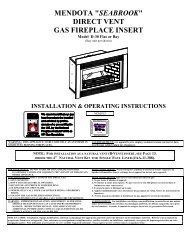
85‐03‐00779IntroductionThe <strong>Mendota</strong> <strong>Heat</strong> Dump Kit [#AA‐11‐00943] is designed to extract heat from <strong>Mendota</strong> ZC Fireplaces and expel it to a desired and predetermined location in another room inthe home, to a basement space, to the unheated attic space or to the exterior of the home. The <strong>Heat</strong> Dump Kit, when installed and connected to a <strong>Mendota</strong> Fireplace, asintended and communicated in these instructions, will extract 95% of the convective heat generated by the <strong>Mendota</strong> Fireplace and transfer it to the desired location. Table 1shows the amount of heat that the <strong>Heat</strong> Dump Kit will extract from specific <strong>Mendota</strong> Fireplace Models.The <strong>Mendota</strong> <strong>Heat</strong> Dump Kit may be installed with up to two (2) <strong>Mendota</strong> <strong>Heat</strong> Zone Kits [#AA‐11‐00998, not supplied with this kit, which allows you to manually change thelocation to which the heat is transferred at anytime. This is a versatile feature that allows you to dump the heat outside the home or to an unheated attic space when heat is notdesired and to an interior room when heat is desired. Consider installing the <strong>Mendota</strong> <strong>Heat</strong> Zone Kit in conjunction with the <strong>Mendota</strong> <strong>Heat</strong> Dump Kit [ordered separately].TABLE 1FIREPLACE MODEL TOTAL HEAT TRANSFER (BTUH) HEAT TRANSFER TO OUTLET #1 HEAT TRANFER TO OUTLET #2DXV‐35 25,000 12,500 12,500DXV‐42 32,000 16,000 16,000DXV‐45 35,000 17,500 17,500DXV‐60 46,000 23,000 23,000FV‐41 28,000 14,000 14,000M‐50 40,000 20,000 20,000The figure, below, shows the possible locations for the <strong>Heat</strong> Dump Outlets. Due to Fire Codes, <strong>Heat</strong> Dump Outlets are not allowed in Garages.FIGURE 1: HEAT DUMP OUTLET LOCATION OPTIONSFOR ATTICHEAT DUMP INSTALLATIONFOR OUTDOORHEAT DUMP INSTALLATIONFOR ENCLOSEDPORCH/DECKFOR OUTDOORHEAT DUMP INSTALLATIONMENDOTA FIREPLACES[DXV35, DXV45, DXV60, M50, FV41]FOR INTERIOR ROOMOR BASEMENTHEAT ZONE INSTALLATION3
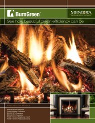
85‐03‐00779WARNINGS1. THE HEAT DUMP BLOWERS MUST BE INSTALLED AND WIRED TOGETHER EXACTLY AS INSTRUCTED IN THESE INSTRUCTIONS.2. BOTH HEAT DUMP BLOWERS MUST OPERATE AT THEIR MAXIMUM RPM RATINGS AT ALL TIMES DURING OPERATION OF THE HEAT DUMP KIT.3. THE HEAT DUMP BLOWER’S SPEED CANNOT BE CONTROLLED. MOTOR SPEED CONTROL DEVICES ARE NOT ALLOWED. ADDITION OF ANY SPEED CONTROL DEVICE TOTHE HEAT DUMP BLOWER CIRCUIT WILL VOID ALL APPLICABLE WARRANTY.<strong>Mendota</strong> <strong>Heat</strong> Dump Kit ‐ Features• Extracts 95% of the fireplace’s heat and expels it out of the home, to the basement, attic or any desired location.• At the flip of a switch, converts the most efficient fireplace in the industry(<strong>Mendota</strong> Model M50 w/ 90%+ steady state efficiency)and other <strong>Mendota</strong> high efficiencyfireplaces to decorative appliances that yield beautiful dancing flames and ember glow effects while only adding soothing radiant heat in small doses to the room.• One Switch controls both <strong>Heat</strong> Dump Blowers. Switch may be mounted anywhere in the home.• Allows installation of large and high BTUH rated <strong>Mendota</strong> Fireplaces in smaller areas of the home without concerns of overheating the small space.• Allows extended use of <strong>Mendota</strong> <strong>Heat</strong>er Rated Fireplaces year round, even in warmer climates.• Highest Quality Centrifugal Blowers used are Super‐quiet during operation and yield only air flow noise similar to furnace air return duct openings’ noise.• Simple Flexible duct installation with duct runs up to 40 feet per run (40 feet allowed for each blower).• Dual back‐flow prevention dampers are integrated into each heat dump circuit to keep cold air out at the cap and to prevent heated air from entering heat dump ductswhen heat dump fans are not in use.• Paintable vent cap arrives with a primer coat, ready to paint to match any home exterior finish color.• Inspection and maintenance of blower system is extremely easy. Removing vent cap provides complete access to heat dump blower.MakeUp Air Requirements –In order to move heat from one location to another, it is necessary to move heated air. The <strong>Mendota</strong> <strong>Heat</strong> Dump <strong>System</strong> has been designed to extract 450 CFMof heated air when both heat outlets are ducted to the outside of the home. When the heat is “dumped” outside the home, the air removed from the homemust be replaced with fresh air to prevent the creation of negative pressure inside the home.Newer central furnaces include makeup air damper mechanisms. Check the function of the makeup air damper installed in the existing central furnace of thehome. Some systems are designed to operate if a negative pressure is detected inside the home. Other systems only operate while the central furnace blower isoperating. Check the existing system and determine if additional Makeup Air Dampers are required.Makeup Air Dampers are readily available at local HVAC supply stores and through HVAC contractors. The Makeup Air dampers shall be sizedbased on the number of cubic feet of air expelled to the exterior of the home. One of the <strong>Heat</strong> Dump Blowers extracts approximately 225 CFM.If both <strong>Heat</strong> Dump Blowers are ducted to the exterior of the home, use 450 CFM as the volume of air extracted per minute to calculate theMakeup Air Damper size.If deemed necessary, add one or two Make‐Up Air Dampers in the home to replace the air that is expelled out of the home. Installing the Makeup Air Dampers inthe ceiling at the opposite end of the home from where the fireplace is located is recommended. Alternatively, install the makeup air dampers at a high level ofa vaulted ceiling. This will help dilute the cold incoming air with air that is normally higher in temperature than areas that are normally habituated.4
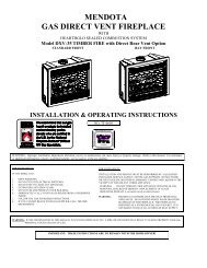
85‐03‐00779Electrical Requirements – One SPST 110 VAC Switch (single switch) is supplied with the <strong>Heat</strong> Dump KitThe two <strong>Heat</strong> Dump Blowers supplied for the <strong>Mendota</strong> <strong>Heat</strong> Dump Kit use a total of 3 Amps at 110VAC. You may install a dedicated 10 Amp circuit for the <strong>Heat</strong>Dump Kit and its accessory Zone Damper Kits. Alternatively, you may tap power from an existing 10, 15 or 20 Amp circuit in the home if the maximum electricalload on that circuit will not exceed the Amp Rating of that circuit after the <strong>Heat</strong> Dump Kit is installed.A Single On/Off switch is supplied with the <strong>Heat</strong> Dump Kit to control both the <strong>Heat</strong> Dump Blowers. You must connect both blowers to this switch. If you areinstalling one or two <strong>Mendota</strong> <strong>Heat</strong> Zone Kits in addition to the <strong>Heat</strong> Dump Kit, you must install a double or triple switch that provide integrated control of alldump and zone components in a small package.INFORMATION ABOUT INSTALLING SWITCHES FOR HEAT DUMP KIT AND HEAT ZONE KITSIf you are installing a <strong>Mendota</strong> <strong>Heat</strong> Zone Kit [#AA‐11‐00998 in addition to this <strong>Mendota</strong> <strong>Heat</strong> Dump Kit, you must order a double or triple switch based on oneor two <strong>Heat</strong> Zone Kits you are installing. <strong>Mendota</strong> offers compact double or triple switches that fit in a single‐gang electrical box to control the <strong>Heat</strong> Dump Kitand either one or two <strong>Heat</strong> Zone Kits. Use a Double Switch if installing a single <strong>Heat</strong> Zone Kit with the <strong>Heat</strong> Dump Kit. Use a triple Switch if installing two<strong>Heat</strong> Zone Kits with the <strong>Heat</strong> Dump Kit. Contact your <strong>Mendota</strong> Dealer to obtain the appropriate switch kit.A SINGLE SWITCH [110VAC] ISPACKAGED WITH THE HEAT DUMP KIT.TWO SWITCH OPTIONS EXIST AND ARE AVAILABLE WHEN INSTALLING HEAT ZONE KITS.SELECT A DOUBLE OR TRIPLE SWITCH BASED ON ONE OR TWO HEAT ZONE KITS INSTALLED.SINGLE SWITCHUSE IF ONLY A HEAT DUMP KIT IS INSTALLED.HEAT DUMPBLOWERS SWITCHTRIPLE SWITCHUSE IF TWO ZONE KITS ARE INSTALLED WITH A HEAT DUMP KIT.HEAT DUMPBLOWERSSWITCHHEAT DUMPBLOWERSSWITCHDOUBLE SWITCHUSE IF ONE ZONE KIT IS INSTALLED WITH AHEAT DUMP KIT.HEAT ZONE #1SWITCHHEAT ZONE #2SWITCH5
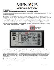
85‐03‐00779<strong>Heat</strong> Dump Kit Ducting Requirements – 20 feet long, 6”‐diameter Flex Duct is suppliedOne 20 feet long, 6” diameter flex duct is provided with the <strong>Heat</strong> Dump Kit. Cut this flex duct into four primary pieces: Two (2) 12 inch long pieces to connect the bloweroutlets to the heat dump caps and Two (2) pieces to the desired lengths to connect the fireplace <strong>Heat</strong> Dump outlets to the <strong>Heat</strong> Dump Blowers. For extensions of the heatdump circuit beyond the distance you can achieve with the 20 feet supplied, you may order additional flexible duct in 25 feet increments from <strong>Mendota</strong> or you may usesingle‐wall rigid galvanized steel ducts and components that are commonly available at local Home Improvement and Hardware stores.Maximum 40 feet length of duct is allowed per run from each blower outlet to the heat dump cap or grill. You may install an additional 15 feet of duct between thefireplace and the blower inlet in addition to the 40 feet from theblower outlet to the <strong>Heat</strong> Dump cap or grill. Any Grill or vent coverWHITE WIRING: HEAT DUMP KITinstalled at heat outlets must be a minimum of 60% open to reduce(NEUTRAL)NOTE: GROUND TERMINALSairflow restriction and to prevent overheating of the blower motors. 110 VACNOT SHOWN. CONNECTThe blower motors are designed to be thermally protected and willBLACKGROUND TERMINALS OF ALLshut down if restrictions in the ducting cause the motor temperatures(HOT)MOTORS AND COMPONENTSto increase beyond 140F.TO COMMON GROUND WIRE.Up to Four (4) 90 degree turns are allowed if rigid‐metal 90 0 elbowsare used to make turns in the duct system. It is highly recommendedthat rigid metal elbows be used to make full 90 0 turns for smoothairflow‐direction changes.If the flexible duct is bent in 90 0 turns, a maximum of two (2) 90 0turns are allowed. Bending the flexible duct to make turns createshigher air‐flow restriction when compared to smooth‐rigid‐metalducts.Clearance Requirements to Ducts ‐ 1” clearance from ductsurface to combustibles within 6 feet of the fireplace connection. Zero(0)” clearance from duct surfaces to combustibles beyond the first 6feet from the fireplace connection.Insulation Requirements – It is recommended that the ductsbe insulated to prevent heat loss through the duct if using ducts totransfer heat to remote rooms in the home. Use unfaced fiberglassbatting insulation or commonly available duct insulation.Electrical Connections ‐All wiring is to be done using 3‐conductors 14 Gage, Solid Coppercable. Common 14‐2 solid copper wire cable shall be used for allwiring and the wiring must be routed per local and National ElectricalCodes. Only those knowledgeable of household wiring practices shallperform the electrical wire routing and wiring connections for the<strong>Mendota</strong> <strong>Heat</strong> Dump Kit.The figures, on this page, depict the wiring schematic for connectingthe <strong>Mendota</strong> <strong>Heat</strong> Dump Kit and the, optional, <strong>Heat</strong> Zone Dampers.SPSTSWITCHWHITE(NEUTRAL)110 VACBLACK(HOT)DOUBLESWITCHWHITE(NEUTRAL)110 VACBLACK(HOT)TRIPLESWITCHBLOWER 1 BLOWER 2WIRING: HEAT DUMP KIT & ONE ZONE KITZONEBLOWER 1 BLOWER 2DAMPER 1WIRING: HEAT DUMP KIT & TWO ZONE KITSZONEBLOWER 1 BLOWER 2DAMPER 1ZONEDAMPER 26
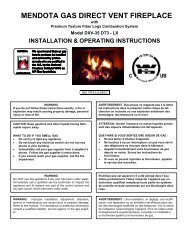
Allowances for Ducting:1. A maximum of 40 feet of duct is allowed per heat dump circuit run.2. Up to Four (4) 90 degree turns are allowed ONLY IF rigid metal 90 0 elbows are used to make turns in the ductsystem. If bending the flexible duct to make turns, a maximum of Two (2) 90 degree turns are allowed. It ishighly recommended that rigid metal elbows be used to make full 90 degree turns for smooth airflowdirectional changes.3. Clearances to Combustible Materials Requirements to Ducts = 1” within 6 feet of fireplace connection. 0”clearance beyond the first 6 feet from fireplace connection.4. Insulating the ducts is recommended to prevent heat loss through the duct if using the ducts to transfer heatto remote rooms in the home. Use unfaced fiberglass batting insulation or commonly available ductinsulation.Connecting to top of fireplace On the top surface of <strong>Mendota</strong> DXV35, DXV42, DXV45, DXV60, M50 and FV41 Zero Clearance Fireplaces, you will findtwo round and partially cut circles indicating the openings for the <strong>Mendota</strong> Versi<strong>Heat</strong> or <strong>Mendota</strong> <strong>Heat</strong> Dumpadapter. Use tin snips to cut the micro joints along the circle perimeter and remove the two metal circles and discard.Inside, in some models, you will find insulation material. Using a hacksaw blade vertically cut circular piece of theinsulation layers within the round openings. Remove the circular pieces of insulation and discard. Below the layers ofinsulation, you will find another circular metal with microjoints. Use tin snips to cut the micro joints and remove thetwo circular plates. You should now see the firebox top.Some models may have additional layers of insulation andsheet metal.Insert the 8” side of the starter adapter into the 8” holes.Make certain that the spring loaded damper securedinside the 8x6 adapter is positioned correctly to openupward when the <strong>Heat</strong> Dump Blower applies suction.Secure the adapter to the top of the fireplace by driving#8x1/2 self drilling screws through holes in the small L‐brackets that are attached to the 8” to 6” Reducer.85‐03‐00779INFORMATION ON SPRING LOADED DAMPER The Spring Loaded Damper installed inside the 8”X6”adapter is designed to open only when the <strong>Heat</strong> DumpBlowers are activated. When the <strong>Heat</strong> Dump Blowers areOFF, these dampers will close automatically and remainclosed preventing cold drafts from entering the fireplacecavity and the home.While installing, make certain that these spring loadeddampers open when pushed upward and close when noforce is applied. Perform this check as a final check duringinstallation. If you find a damper installed backwards, call<strong>Mendota</strong> Technical Support.7
Framing the Opening for caps in outside wall Frame a square 11” X 11” opening for each <strong>Heat</strong> Dump Cap at the designated locationon the selected exterior wall. Frame as shown. It is important that you frame theopening exactly as shown. A smaller opening will not allow you to remove the <strong>Heat</strong>Dump Blower for cleaning or servicing purposes in the future.Note: The <strong>Heat</strong> Dump Caps are not required to be directly behind the fireplace. They maybe installed directly behind the fireplace on the side walls of exterior chases. Installationon the side walls of an exterior chase will make the <strong>Heat</strong> Dump Caps less visible andaesthetically more appealing.Cutting Flexible Duct to Required Lengths –The supplied 6” flexible duct is 20 feet long, when stretched out. First, cut two 12”lengths (stretched). These two pieces will connect between the <strong>Heat</strong> Dump BlowerOutlets and the <strong>Heat</strong> Dump Caps.85‐03‐00779Second, Measure the distance from each outlet on the fireplace top to the location of the<strong>Heat</strong> Dump Caps. Always budget an extra 12 inches for each leg of the duct running tothe <strong>Heat</strong> Dump Cap. If more than a total of 18 feet is required for two <strong>Heat</strong> Dump Ductruns, you will need to supply additional lengths of 6” flexible aluminum duct or 6” rigidmetal ducts to make up the difference.Cut the flexible 6” Aluminum duct to the required lengths plus 12 inches, as measuredfor each duct run from the fireplace top to the blowers’ inlet locations.Connecting flexible ducts to fireplace –Slide one end of each flexible 6” duct piece over the 6” starter collar on the 8”X6” adapteryou installed on the top of the fireplace. Secure the flexible Aluminum duct to each of the6” collars by tightening a hose clamp, provided with this kit.8
Mounting Blowers to Outside Wall –Center each blower in the framed opening (11” X 11”). Orient the blower sothat the inlet is facing inside the home and the outlet is facing outside thehome. Center the blower in the framed opening. Secure the “L” bracketflanges to the outside of the walls on top of the sheathing (plywood or OSB).WARNING: Do not bury the bracket under the sheathing material orSiding material. If you do so, you will not be able to remove theblower for service or repair needs.85‐03‐00779Connecting flexible ducts to Blowers –1. Stretch‐out and connect the flex from each fireplace outlet to a <strong>Heat</strong>Dump Blower’s inlet flange. Secure flex to blower using Hose Clamps,provided.2. Connect the 12” piece of flex pieces that you cut earlier to the outletflanges on the <strong>Heat</strong> Dump Blowers. Secure flex to Blower OutletFlange by tightening Hose Clamps provided with this kit over the flextube ends.WARNINGHEAT DUMP BLOWER BRACKETS MUST BE INSTALLEDON TOP OF EXTERIOR SHEATHING MATERIAL.9
85‐03‐00779Connecting flexible ducts from blower to Cap and attaching Cap to wall –1. Connect the loosed end of the 12” flexible duct pieces to the inlet end of one of the two <strong>Heat</strong> Dump Caps.2. Secure flex hose to the <strong>Heat</strong> Dump Cap’s inlet flange by tightening a hose clamp, supplied with this kit.3. Compress 12” long flex between blower and cap as you push cap into place. Secure <strong>Heat</strong> Dump Cap to exterior wall, centered over <strong>Heat</strong> Dump Blower outlet,using exterior‐grade drywall screws or wood screws. Repeat steps 1, 2 and 3 for 2 nd <strong>Heat</strong> Dump Cap.‐ WARNING –THE HEAT DUMP CAPS MUST BE SECURED ON TOP OF ANY EXTERIOR SHEATHINGMATERIALS. SIDING MUST BE INSTALLED OUTSIDE CAP PERIMETERS.10
INSTRUCTIONS FOR ATTACHING THE BLOWER MOUNTING BRACKETS TO THE BLOWER HOUSING –1. Locate the Blower Mounting Brackets. Four brackets are included in this kit.2. Align hole and open slot in Blower Mounting Bracket with holes on the housing sides of the blower.3. Secure Blower Mounting Brackets to Blower.85‐03‐0077911
85‐03‐00779GENERAL MAINTENANCE INSTRUCTIONS –General maintenance for the <strong>Mendota</strong> <strong>Heat</strong> Dump kits includes occasional cleaning of the duct system. It is recommended that the <strong>Heat</strong> Dump Ducts be cleanedusing soft duct brushes once every 4 to 5 years.The blowers are of superior quality and employ permanently lubricated sealed bearings. These Blower Motors do not require oiling.DATEMAINTENANCE LOG AND NOTESDETAILS12