OPIsystems Cable Installation 2012-10-2.pdf - Westeel
OPIsystems Cable Installation 2012-10-2.pdf - Westeel
OPIsystems Cable Installation 2012-10-2.pdf - Westeel

You also want an ePaper? Increase the reach of your titles
YUMPU automatically turns print PDFs into web optimized ePapers that Google loves.
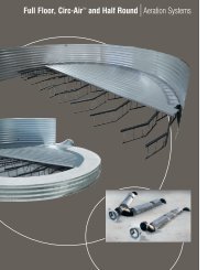
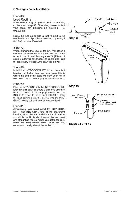
OPI-integris <strong>Cable</strong> <strong>Installation</strong>Step #6Lead RoutingIf the lead is to go to ground level for readout,continue with step #6. Otherwise, please contactyour dealer for directions on installing RTU,0XLE,s etc.Route the lead along side a roof rib next to theroof ladder and clip with a screw and clip every 4ft (1.2m) or closer if desired.Step #6Step #7When rounding the eave of the bin, first attach aclip near the end of the roof sheet, then loop backunder to the bin wall, leaving about 3” (75mm) ofslack to allow for expansion and contraction. Clipthe lead every 4 feet (1.2m) down the bin wall.Step #8Install the INT2-DOCK-SHRT in a convenientlocation not higher than eye level since this iswhere the end of the cable will stay when not inuse. Attach with 2 self-tapping screws as shown.Step #9Plug the INT2-GRND into the INT2-DOCK-SHRT,loop the lead down to create a drip loop and thenback up. Install 2 self-tapping screws into theINT2-GRND next to the INT2-DOCK-SHRT. Plugthe lead coming down the bin wall into the INT2-GRND. Neatly coil and stow any excess lead.Step #<strong>10</strong>Alternatively, you could install the INT2-DOCK-SHRT and INT2-GRND first at the convenientlocation, attach the lead and clip to the bin wall asyou climb the bin ladder, keeping the lead neatand straight as you go. When you get to the roof,install the temperature cable. Then coil anyexcess and neatly stow at the rooftop.Step #7Steps #8 and #9Subject to change without notice 6Rev 2.2 <strong>2012</strong>/<strong>10</strong>/2