OPIsystems Cable Installation 2012-10-2.pdf - Westeel
OPIsystems Cable Installation 2012-10-2.pdf - Westeel
OPIsystems Cable Installation 2012-10-2.pdf - Westeel

You also want an ePaper? Increase the reach of your titles
YUMPU automatically turns print PDFs into web optimized ePapers that Google loves.
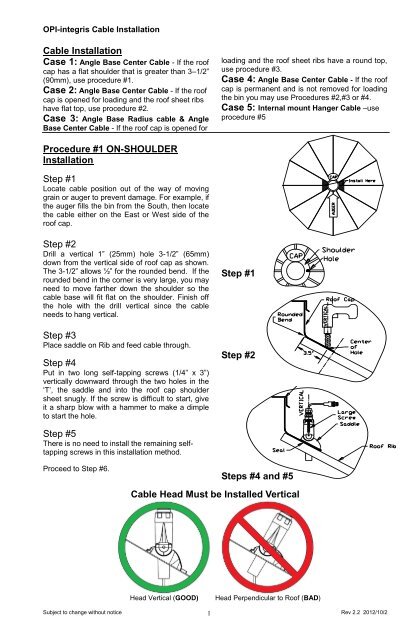
OPI-integris <strong>Cable</strong> <strong>Installation</strong><strong>Cable</strong> <strong>Installation</strong>Case 1: Angle Base Center <strong>Cable</strong> - If the roofcap has a flat shoulder that is greater than 3–1/2”(90mm), use procedure #1.Case 2: Angle Base Center <strong>Cable</strong> - If the roofcap is opened for loading and the roof sheet ribshave flat top, use procedure #2.Case 3: Angle Base Radius cable & AngleBase Center <strong>Cable</strong> - If the roof cap is opened forloading and the roof sheet ribs have a round top,use procedure #3.Case 4: Angle Base Center <strong>Cable</strong> - If the roofcap is permanent and is not removed for loadingthe bin you may use Procedures #2,#3 or #4.Case 5: Internal mount Hanger <strong>Cable</strong> –useprocedure #5Procedure #1 ON-SHOULDER<strong>Installation</strong>Step #1Locate cable position out of the way of movinggrain or auger to prevent damage. For example, ifthe auger fills the bin from the South, then locatethe cable either on the East or West side of theroof cap.Step #2Drill a vertical 1” (25mm) hole 3-1/2” (65mm)down from the vertical side of roof cap as shown.The 3-1/2” allows ½” for the rounded bend. If therounded bend in the corner is very large, you mayneed to move farther down the shoulder so thecable base will fit flat on the shoulder. Finish offthe hole with the drill vertical since the cableneeds to hang vertical.Step #3Place saddle on Rib and feed cable through.Step #4Put in two long self-tapping screws (1/4” x 3”)vertically downward through the two holes in the‘T’, the saddle and into the roof cap shouldersheet snugly. If the screw is difficult to start, giveit a sharp blow with a hammer to make a dimpleto start the hole.Step #1Step #2Step #5There is no need to install the remaining selftappingscrews in this installation method.Proceed to Step #6.Steps #4 and #5<strong>Cable</strong> Head Must be Installed VerticalHead Vertical (GOOD)Head Perpendicular to Roof (BAD)Subject to change without notice 1Rev 2.2 <strong>2012</strong>/<strong>10</strong>/2
OPI-integris <strong>Cable</strong> <strong>Installation</strong>Procedure #2 ON-RIB <strong>Installation</strong>Step #1Locate cable position out of the way of movinggrain or auger to prevent damage. For example, ifthe auger fills the bin from the South, then locatethe cable either on the East or West side of theroof cap.Step #2Drill a vertical 1” (25mm) hole 2” (50mm) downfrom the edge of roof cap as shown. Finish off thehole with the drill vertical since the cable needs tohang vertical.Step #3Place saddle on Rib and feed cable throughStep #4Put in two bolts provided (1/4”x2”) through the ‘T’and saddle and apply nuts from underneath. Holdthe cable exactly vertical and tighten the boltssecurely.Step #5Install a self-tapping screw in the tab hole at thelower edge of the saddle to secure saddle to rib.Install a self-tapping screw and washer just abovethe tab at the top edge of the saddle to hold thesaddle down. The washer overlaps the edge ofthe tab to hold in place.Step #1Step #2Proceed to Step #6.Steps #4 and #5<strong>Cable</strong> Head Must be Installed VerticalHead Vertical (GOOD)Head Perpendicular to Roof (BAD)Subject to change without notice 2Rev 2.2 <strong>2012</strong>/<strong>10</strong>/2
OPI-integris <strong>Cable</strong> <strong>Installation</strong>Procedure #3 BETWEEN-RIB<strong>Installation</strong>Step #1Locate cable position out of the way of movinggrain or auger to prevent damage. For example, ifthe auger fills the bin from the South, then locatethe cable either on the East or West side of theroof cap.Step #2Position the saddle flat between two ribs(mounting tab with hole facing down the roof) asnear as the cap as possible so the saddle justtouches the two ribs with the upper corners. Markthe position of the hole in the lower mounting tabonto the roof sheet. Drill a vertical 1” (25mm) hole1-1/2” (38mm) up the roof from the mark. Finishoff the hole with the drill vertical since the cableneeds to hang vertical.Step #3Place saddle over the hole and feed the cablethrough the hole.Step #4With the cable held exactly vertical, screw in thetwo long self-tapping screws (1/4” x 3”) verticallydownward through the two holes in the ‘T’, thesaddle and into the roof sheet snugly. IF thescrew is difficult to start, give it a sharp blow witha hammer to make a dimple to start the hole.Step #5Install a self-tapping screw in the tab hole at thelower edge of the saddle to secure saddle to roofsheet. Install a self-tapping screw and washer justabove the tab at the top edge of the saddle tohold the saddle down. The washer overlaps theedge of the tab to hold in place.Step #1Step #2Proceed to Step #6.Steps #4 and #5<strong>Cable</strong> Head Must be Installed VerticalHead Vertical (GOOD)Head Perpendicular to Roof (BAD)Subject to change without notice 3Rev 2.2 <strong>2012</strong>/<strong>10</strong>/2
OPI-integris <strong>Cable</strong> <strong>Installation</strong>Procedure #4 PERMANENT ROOFCAP <strong>Installation</strong>Step #1Locate cable position out of the way of movinggrain or auger to prevent damage. For example, ifthe pump or spout fills the bin from the South,then locate the cable either on the East or Westside of the roof cap.Step #2Drill a vertical 1” (25mm) hole at the chosenlocation on the flat (top) of the roof cap.Step #3Place saddle over the hole and feed the cablethrough the hole.Step #4With the cable held exactly vertical, screw in thetwo long self-tapping screws (1/4” x 3”) verticallydownward through the two holes in the ‘T’, thesaddle and into the roof sheet snugly. If the screwis difficult to start and the material is thicker than1/8” (3mm) you may need to drill a pilot hole first.Step #5Install a self-tapping screw in the tab hole at thelower edge of the saddle to secure saddle to roofcap. Install a self-tapping screw and washer justabove the tab at the top edge of the saddle tohold the saddle down. The washer overlaps theedge of the tab to hold in place.Proceed to Step #6.Step #1Steps #4 and #5<strong>Cable</strong> Head Must be Installed VerticalHead Vertical (GOOD)Head Not Vertical (BAD)Subject to change without notice 4Rev 2.2 <strong>2012</strong>/<strong>10</strong>/2
OPI-integris <strong>Cable</strong> <strong>Installation</strong>Procedure #5 HANGER <strong>Installation</strong>Step #1Attach hanger bracket to rafter according tomanufacturer’s specifications. OR. Attach eyebolt torafter so that it is parallel to the rafter.Step #2Loop A-bolt through hole in rafter, bracket, or eyebolt,or over hanger rod. Insert hanger through holes inthe cable head. Apply nyloc-nuts to threadsbelow cable head. Thread nuts on so that thereis 1” of threads below nut. There is no nut on topside of ‘T’; this is normal.Step #3Uncoil the cable. Do not drop the cable. Do notallow cable to knot on itself.Step #4Check that the cable hangs straight down fromrafter and is free to move. Lack of freemovement can result in hanger and/or cablefailure.Step #5Attach lead to rafter with wire clip so that there is1ft of slack in the lead through the range of cablemovement.Proceed to Step #6Use Forged Steel, Shouldered Eyebolts3/8” Eyebolt 5/8” EyeboltMDR, moistureCDR, HDREyebolt Must be Parallel to the RafterEyebolt Parallel to Rafter (GOOD)Eyebolt Perpendicular to Rafter (BAD)Subject to change without notice 5Rev 2.2 <strong>2012</strong>/<strong>10</strong>/2
OPI-integris <strong>Cable</strong> <strong>Installation</strong>Step #6Lead RoutingIf the lead is to go to ground level for readout,continue with step #6. Otherwise, please contactyour dealer for directions on installing RTU,0XLE,s etc.Route the lead along side a roof rib next to theroof ladder and clip with a screw and clip every 4ft (1.2m) or closer if desired.Step #6Step #7When rounding the eave of the bin, first attach aclip near the end of the roof sheet, then loop backunder to the bin wall, leaving about 3” (75mm) ofslack to allow for expansion and contraction. Clipthe lead every 4 feet (1.2m) down the bin wall.Step #8Install the INT2-DOCK-SHRT in a convenientlocation not higher than eye level since this iswhere the end of the cable will stay when not inuse. Attach with 2 self-tapping screws as shown.Step #9Plug the INT2-GRND into the INT2-DOCK-SHRT,loop the lead down to create a drip loop and thenback up. Install 2 self-tapping screws into theINT2-GRND next to the INT2-DOCK-SHRT. Plugthe lead coming down the bin wall into the INT2-GRND. Neatly coil and stow any excess lead.Step #<strong>10</strong>Alternatively, you could install the INT2-DOCK-SHRT and INT2-GRND first at the convenientlocation, attach the lead and clip to the bin wall asyou climb the bin ladder, keeping the lead neatand straight as you go. When you get to the roof,install the temperature cable. Then coil anyexcess and neatly stow at the rooftop.Step #7Steps #8 and #9Subject to change without notice 6Rev 2.2 <strong>2012</strong>/<strong>10</strong>/2
OPI-integris <strong>Cable</strong> <strong>Installation</strong><strong>Cable</strong> Grounding(1) Angle Base Ground Attachment<strong>Cable</strong>s must be installed so that the cable heador top loop has electrical conductivity to earthground. Typical installations in metal bins shouldprovide adequate grounding. Other installationswith weak, or no path to ground at the cablehead, ie: concrete structures, require dedicatedconnection to ground to protect the cable. It isrecommended that all ground connections bemade with 14-16awg ring terminals crimped to1/16” galvanized steel cable, for corrosionresistance.(1) For cables with an angle base, attach the ringterminal to any fastener used to mount thebase.(2) For MDR and moisture hangers, apply thering terminal over the exposed thread belowone of the nuts and secure with a second5/16-24 UNF nut.For CDR and HDR hangers, apply the ringterminal over the exposed thread below oneof the nuts and secure with a second 3/8-24UNF nut.(2) Hanger Ground AttachmentSubject to change without notice 7Rev 2.2 <strong>2012</strong>/<strong>10</strong>/2