4.05 Microbiological Examination of Non-sterile Products
4.05 Microbiological Examination of Non-sterile Products
4.05 Microbiological Examination of Non-sterile Products
- No tags were found...

You also want an ePaper? Increase the reach of your titles
YUMPU automatically turns print PDFs into web optimized ePapers that Google loves.
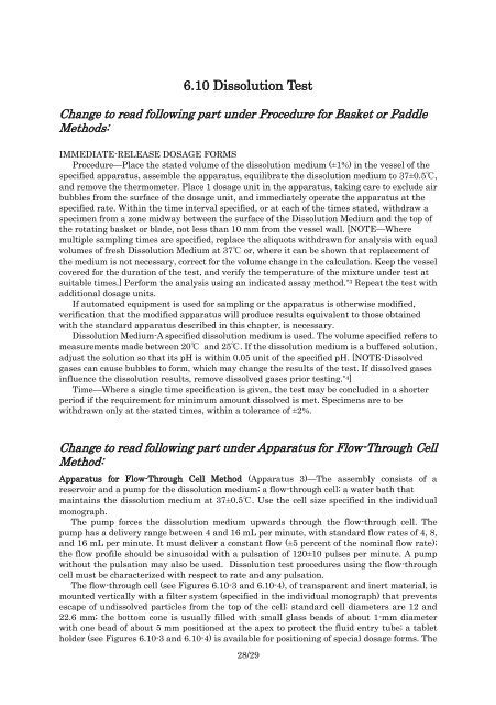
6.10 Dissolution TestChange to read following part under Procedure for Basket or PaddleMethods:IMMEDIATE-RELEASE DOSAGE FORMSProcedure—Place the stated volume <strong>of</strong> the dissolution medium (±1%) in the vessel <strong>of</strong> thespecified apparatus, assemble the apparatus, equilibrate the dissolution medium to 37±0.5℃,and remove the thermometer. Place 1 dosage unit in the apparatus, taking care to exclude airbubbles from the surface <strong>of</strong> the dosage unit, and immediately operate the apparatus at thespecified rate. Within the time interval specified, or at each <strong>of</strong> the times stated, withdraw aspecimen from a zone midway between the surface <strong>of</strong> the Dissolution Medium and the top <strong>of</strong>the rotating basket or blade, not less than 10 mm from the vessel wall. [NOTE—Wheremultiple sampling times are specified, replace the aliquots withdrawn for analysis with equalvolumes <strong>of</strong> fresh Dissolution Medium at 37℃ or, where it can be shown that replacement <strong>of</strong>the medium is not necessary, correct for the volume change in the calculation. Keep the vesselcovered for the duration <strong>of</strong> the test, and verify the temperature <strong>of</strong> the mixture under test atsuitable times.] Perform the analysis using an indicated assay method. *3 Repeat the test withadditional dosage units.If automated equipment is used for sampling or the apparatus is otherwise modified,verification that the modified apparatus will produce results equivalent to those obtainedwith the standard apparatus described in this chapter, is necessary.Dissolution Medium-A specified dissolution medium is used. The volume specified refers tomeasurements made between 20℃ and 25℃. If the dissolution medium is a buffered solution,adjust the solution so that its pH is within 0.05 unit <strong>of</strong> the specified pH. [NOTE-Dissolvedgases can cause bubbles to form, which may change the results <strong>of</strong> the test. If dissolved gasesinfluence the dissolution results, remove dissolved gases prior testing. *4 ]Time—Where a single time specification is given, the test may be concluded in a shorterperiod if the requirement for minimum amount dissolved is met. Specimens are to bewithdrawn only at the stated times, within a tolerance <strong>of</strong> ±2%.Change to read following part under Apparatus for Flow-Through CellMethod:Apparatus for Flow-Through Cell Method (Apparatus 3)—The assembly consists <strong>of</strong> areservoir and a pump for the dissolution medium; a flow-through cell; a water bath thatmaintains the dissolution medium at 37±0.5℃. Use the cell size specified in the individualmonograph.The pump forces the dissolution medium upwards through the flow-through cell. Thepump has a delivery range between 4 and 16 mL per minute, with standard flow rates <strong>of</strong> 4, 8,and 16 mL per minute. It must deliver a constant flow (±5 percent <strong>of</strong> the nominal flow rate);the flow pr<strong>of</strong>ile should be sinusoidal with a pulsation <strong>of</strong> 120±10 pulses per minute. A pumpwithout the pulsation may also be used. Dissolution test procedures using the flow-throughcell must be characterized with respect to rate and any pulsation.The flow-through cell (see Figures 6.10-3 and 6.10-4), <strong>of</strong> transparent and inert material, ismounted vertically with a filter system (specified in the individual monograph) that preventsescape <strong>of</strong> undissolved particles from the top <strong>of</strong> the cell; standard cell diameters are 12 and22.6 mm; the bottom cone is usually filled with small glass beads <strong>of</strong> about 1-mm diameterwith one bead <strong>of</strong> about 5 mm positioned at the apex to protect the fluid entry tube; a tabletholder (see Figures 6.10-3 and 6.10-4) is available for positioning <strong>of</strong> special dosage forms. The28/29