Currents Induced by Electron Motion* - LArTPC DocDB
Currents Induced by Electron Motion* - LArTPC DocDB
Currents Induced by Electron Motion* - LArTPC DocDB

You also want an ePaper? Increase the reach of your titles
YUMPU automatically turns print PDFs into web optimized ePapers that Google loves.
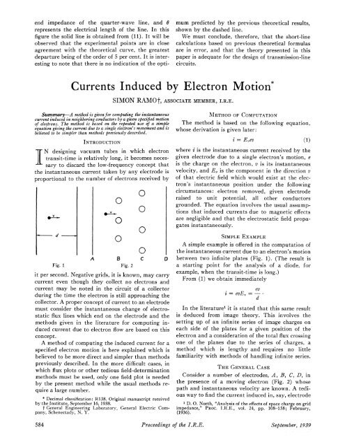
end impedance of the quarter-wave line, and 0represents the electrical length of the line. In thisfigure the solid line is obtained from (11). It will beobserved that the experimental points are in closeagreement with the theoretical curve, the greatestdeparture being of the order of 5 per cent. It is interestingto note that there is no indication of the optimumpredicted <strong>by</strong> the previous theoretical results,shown <strong>by</strong> the dashed line.We must conclude, therefore, that the short-linecalculations based on previous theoretical formulasare in error, and that the theory presented in thispaper is adequate for the design of transmission-linecircuits.<strong>Currents</strong> <strong>Induced</strong> <strong>by</strong> <strong>Electron</strong> <strong>Motion*</strong>Summary-A method is given for computing the instantaneouscurrent induced in neighboring conductors <strong>by</strong> a given specified motionof electrons. The method is based on the repeated use of a simpleequation giving the current due to a single electron's movement and isbelieved to be simpler than methods previously described.INTRODUCTIONN designing vacuum tubes in which electrontransit-time is relatively long, it becomes necessaryto discard the low-frequency concept thatthe instantaneous current taken <strong>by</strong> any electrode isproportional to the number of electrons received <strong>by</strong>dgA B CFig. 1Fig. 2it per second. Negative grids, it is known, may carrycurrent even though they collect no electrons andcurrent may be noted in the circuit of a collectorduring the time the electron is still approaching thecollector. A proper concept of current to an electrodemust consider the instantaneous change of electrostaticflux lines which end on the electrode and themethods given in the literature for computing inducedcurrent due to electron flow are based on thisconcept.A method of computing the induced current for aspecified electron motion is here explained which isbelieved to be more direct and simpler than methodspreviously described. In the more difficult cases, inwhich flux plots or other tedious field-determinationmethods must be used, only one field plot is needed<strong>by</strong> the present method while the usual methods requirea large number.*Decimal classification: R138. Original manuscript received<strong>by</strong> the Institute, September 16, 1938.t General Engineering Laboratory, General Electric Company,Schenectady, N. Y.SIMON RAMOt, ASSOCIATE MEMBER, I.R.E.0000000METHOD OF COMPUTATIONThe method is based on the following equation,whose derivation is given later:i = E,ev (1)where i is the instantaneous current received <strong>by</strong> thegiven electrode due to a single electron's motion, eis the charge on the electron, v is its instantaneousvelocity, and E, is the component in the direction vof that electric field which would exist at the electron'sinstantaneous position under the followingcircumstances: electron removed, given electroderaised to unit potential, all other conductorsgrounded. The equation involves the usual assumptionsthat induced currents due to magnetic effectsare negligible and that the electrostatic field propagatesinstantaneously.SIMPLE EXAMPLEA simple example is offered in the computation ofthe instantaneous current due to an electron's motionbetween two infinite plates (Fig. 1). (The result isa starting point for the analysis of a diode, forexample, when the transit-time is long.)From (1) we obtain immediatelyevi = evE = -dIn the literature' it is stated that this same resultis deduced from image theory. This involves thesetting up of an infinite series of image charges oneach side of the plates for a given position of theelectron and a consideration of the total flux crossingone of the planes due to the series of charges, amethod which is lengthy and requires no littlefamiliarity with methods of handling infinite series.THE GENERAL CASEConsider a number of electrodes, A, B, C, D, inthe presence of a moving electron (Fig. 2) whosepath and instantaneous velocity are known. A tediousway to find the current induced in, say, electrode1 D. 0. North, "Analysis of the effects of space charge on gridimpedance," PROC. I.R.E., vol. 24, pp. 108-158; February,(1936).584 Proceedings of the I.R.E.September, 1939
A is to make a flux plot of the lines of force emanatingfrom the electron, when it is at some point of its path,and note the portion of the total lines which end onA. By making a number of such plots it is possibleto observe the change in the number of lines endingon A as the electron moves, and consequently tocompute the induced current. The accuracy is dependentupon the number of plots made.It is much simpler to use (1). One plot is made forthe case of A at unit potential, B, C, D grounded,and the electron removed, Ev is then known andi= E,ev.Ramo: <strong>Currents</strong> <strong>Induced</strong> <strong>by</strong> <strong>Electron</strong> MotionTo minimize the induced current in a negativegrid, an important consideration in the design ofhigh-frequency amplifiers and oscillators, it may bethat (1) will prove helpful to the designer. The equationstates that the electrode configuration should besuch as to yield minimum E,. If the electron's path,for example, is made to coincide with an equipotentialof the grid (not an equipotential in the fieldin which the electron is traveling, of course, but anequipotential in that artificial field due to unit potentialon the grid, the electron removed, and all elsegrounded) the induced current will be zero. It will notbe possible to realize this for the complete electronicpath, since the electron must start at some equipotentialsurface, but it may be possible to find practicalconfigurations that will approach this conditionover a good share of the path.DERIVATION OF EQUATION (1)Consider the electron, of charge e, in the presenceof any number of grounded conductors, for one ofwhich, say A, the induced current is desired. Surroundthe electron with a tiny equipotential sphere.Then if V is the potential of the electrostatic field,in the region between conductorsV2V = 0where V2 is the Laplacian operator. Call Ve thepotential of the tiny sphere and note that V=0 onthe conductors and- ds = 47rer snsphere's surface(Gauss' law)where a V/an indicates differentiation with respect tothe outward normal to the surface and the integralis taken over the surface of the sphere.Now consider the same set of conductors with theelectron removed, conductor A raised to unit potential,and the other conductors grounded. Call thepotential of the field in this case V', so that V2 V' =0in the space between conductors, including the pointwhere the electron was situated before. Call the newpotential of this point Ve'.Now Green's theorem2 states thatf [V'V2V - VV2V']dvvolumebetweenboundariesaVav'-=_I V'V-V ds.an an_boundarysurfacesChoose the volume to be that bounded <strong>by</strong> theconductors and the tiny sphere. Then the left-handside is zero and the right-hand side may be dividedinto three integrals:(1) Over the surfaces of all conductors except A.This integral is zero since V = V'=0 on thesesurfaces.(2) Over the surface of A. This reduces to-Jf(V)/(an)ds,surface Afor V' = 1 and V =0 for conductor A.(3) Over the surface of the sphere. This becomesr dVr av'- Vet ds+VeV -ds.1 an Jonsphere's surface sphere's surfaceThe second of these integrals is zero <strong>by</strong> Gausslaw since f(( V')/(an)ds is the negative of the chargeenclosed (which was zero for the second case inwhich the electron was removed).Finally, we obtain from (2)ordv rav0O Ī ds-Ve' - dsJ an onsurface A sphere's surface- 47rQA + 4ireVe'QA= - eVe'dQA dVeI [ aye' dx]TA = = -e - = - edt dt L ax dtiwhere x is the direction of motion.NowdxaVe'-= v and = -Ev,dtaxso585(2)= evE,. (1)2 J. H. Jeans, "Electricity and Magnetism," page 160, Cambridge,London, England, (1927).