USG Drywall Suspension System, Curved Drywall Ceilings ...
USG Drywall Suspension System, Curved Drywall Ceilings ...
USG Drywall Suspension System, Curved Drywall Ceilings ...

Create successful ePaper yourself
Turn your PDF publications into a flip-book with our unique Google optimized e-Paper software.
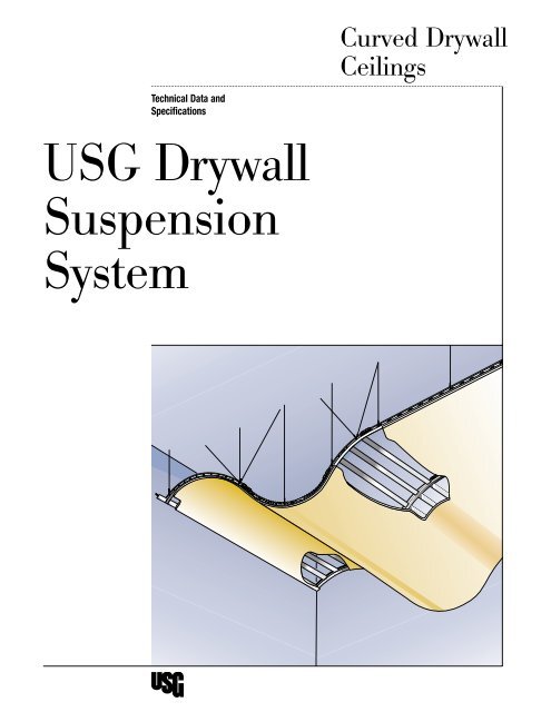
<strong>Curved</strong> <strong>Drywall</strong><strong>Ceilings</strong>Technical Data andSpecifications<strong>USG</strong> <strong>Drywall</strong><strong>Suspension</strong><strong>System</strong>
<strong>USG</strong> <strong>Drywall</strong><strong>Suspension</strong> <strong>System</strong>ContentsIntroduction 4<strong>Curved</strong> <strong>Drywall</strong> <strong>Ceilings</strong> 5Features and Benefits 5Design Information 6<strong>System</strong> Components 6Vault <strong>Drywall</strong> <strong>Ceilings</strong> 8Construction Details 9Vault and Valley <strong>Drywall</strong> <strong>Ceilings</strong> 10Construction Details 11<strong>Curved</strong> Soffits 12Design Information 12Construction Details 13Fascia Applications 14Utility Interfaces 15Accessory Selector 16Application of SHEETROCK ® Brand Gypsum Panels 18Seismic Requirements 20Component Hole Punching 21Architectural Specifications 223
IntroductionThe <strong>USG</strong> <strong>Drywall</strong> <strong>Suspension</strong> <strong>System</strong> is a pre-engineered drywall ceilingsuspension system created to reduce the design and installation difficultiesassociated with other drywall ceilings. It allows the creation of uniquecurved drywall ceilings and conventional flat ceilings with just one system.The <strong>USG</strong> <strong>Drywall</strong> <strong>Suspension</strong> <strong>System</strong> represents a major breakthrough indrywall ceiling construction.<strong>Curved</strong> <strong>Drywall</strong> <strong>Ceilings</strong>The introduction of curved main tees dramatically simplifies the processof designing and building curved drywall ceilings and significantly lowersthe cost.Soffits and Fascia<strong>Curved</strong> and serpentine drywall soffits and fascias can easily be designedand built with the new <strong>USG</strong> <strong>Drywall</strong> <strong>Suspension</strong> <strong>System</strong>.TransitionsNo other suspension system gives you the flexibility to make easy transitionsfrom soffits, flat, or curved drywall ceilings. Transitions from drywall toacoustical ceilings are also easily accomplished.Additional InformationThis Technical Data brochure will guide you through the details of the<strong>USG</strong> <strong>Drywall</strong> <strong>Suspension</strong> <strong>System</strong>. For additional literature, samples, ortechnical assistance, call 1-800-<strong>USG</strong>-4YOU. A complete list of additionalliterature can be found on the back cover of this brochure.4
Features and BenefitsDesign Information<strong>Curved</strong> <strong>Drywall</strong> <strong>Ceilings</strong>The curved components of the <strong>USG</strong> <strong>Drywall</strong> <strong>Suspension</strong> <strong>System</strong> represent a major breakthrough in designing andbuilding curved drywall ceilings.FeatureUnique design templateBenefitSimplifies designing of curved drywall ceilings22 pre-engineered standard curves (11 vaults and valleys) Dramatically eases the design and building of curveddrywall ceilingsSingle source for both the suspension system and gypsumpanels1-800-<strong>USG</strong>-4YOUAll knurled componentsProvides quality assurance on a construction systembasis and a lifetime limited warrantyPuts design and installation information just a phonecall awayEasier screw attachmentDesign InformationThe <strong>USG</strong> <strong>Drywall</strong> <strong>Suspension</strong> <strong>System</strong> makes designing curved drywall ceilings easy. 22 standard curved main tees withradii ranging from 2 6-9/16 to 19 1-3/16 are available in both vault and valley shapes. Combining curved tees andstraight main tees is easily accommodated. To increase design flexibility all main tees (straight and curved) can be fieldcut to specific arc or chord lengths.Here’s how:1. Sketch the rough configuration you want to achieve.2. Use the Design Template (AC3098) to select the specific radii and corresponding main tee components.3. Form the shape of the ceiling (genetic code) by stringing together the main tee components specified in step 2(see diagram below).4. Select SHEETROCK ® Brand Gypsum Panels on the basis of the smallest radius in the genetic code. See pages 18-19for more specific information.NotesSee Utility Interface on page 15 for information regarding lighting considerations with curved ceilings.Step 3vaultvaultvaultvalleyvalleyvalley4 straight4/90 VY4 straight 10/90 VT4 straight 6/90 VY 4 straight 4/90 VT10/90 VY6/90 VTGenetic Code5
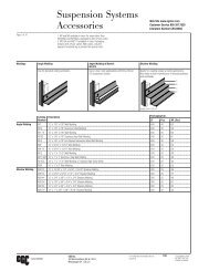
<strong>System</strong> Componentsradiusarc lengthchord lengthchord lengtharc lengthradiusLoadHanger SpacingLength(Lbs./LF)or Arc Face Tee Fire Chord ArcItem # Length Load Width Height Rated Radius Length Angle 2 4Straight Main Tees DGL-26 12 Heavy duty (2) 15/16 1-1/2 Yes — — — — 16.0DGLW-26 12 Heavy duty (2) 1-1/2 1-1/2 Yes — — — — 16.0THE WALL-TO-WALL Main Tee DGL-26s 7 to 14 (1) Heavy duty (2) 15/16 1-1/2 Yes — — — — 16.0DGLW-26s 7 to 14 (1) Heavy duty (2) 1-1/2 1-1/2 Yes — — — — 16.0<strong>Curved</strong> Main Tees Vaults 4/90 VT 4 16 lbs. (3) 15/16 1-1/2 No 2 6-9/16 3 7-3/16 90 — 16.06/90 VT 6 16 lbs. (3) 15/16 1-1/2 No 3 9-15/16 5 4-13/16 90 — 16.08/90 VT 8 16 lbs. (3) 15/16 1-1/2 No 5 1-1/8 7 2-7/16 90 — 16.010/90 VT 10 16 lbs. (3) 15/16 1-1/2 No 6 4-3/8 9 0-1/16 90 — 16.08/60 VT 8 16 lbs. (3) 15/16 1-1/2 No 7 7-11/16 77-11/16 60 — 16.010/60 VT 10 16 lbs. (3) 15/16 1-1/2 No 9 6-5/8 9 6-5/8 60 — 16.08/45 VT 8 16 lbs. (3) 15/16 1-1/2 No 10 2-1/4 7 9-9/16 45 — 16.06/30 VT 6 16 lbs. (3) 15/16 1-1/2 No 11 5-1/2 5 11-3/16 30 — 16.010/45 VT 10 16 lbs. (3) 15/16 1-1/2 No 12 8-13/16 9 8-15/16 45 — 16.08/30 VT 8 16 lbs. (3) 15/16 1-1/2 No 15 3-3/8 7 10-15/16 30 — 16.010/30 VT 10 16 lbs. (3) 15/16 1-1/2 No 19 1-3/16 9 10-5/8 30 — 16.0Valleys 4/90 VY 4 16 lbs. (4) 15/16 1-1/2 No 2 6-9/16 3 7-3/16 90 16.0 —6/90 VY 6 16 lbs. (4) 15/16 1-1/2 No 3 9-15/16 5 4-13/16 90 16.0 —8/90 VY 8 16 lbs. (4) 15/16 1-1/2 No 5 1-1/8 7 2-7/16 90 16.0 —10/90 VY 10 16 lbs. (4) 15/16 1-1/2 No 6 4-3/8 9 0-1/16 90 16.0 —8/60 VY 8 16 lbs. (4) 15/16 1-1/2 No 7 7-11/16 7 7-11/16 60 16.0 —10/60 VY 10 16 lbs. (4) 15/16 1-1/2 No 9 6-5/8 9 6-5/8 60 16.0 —8/45 VY 8 16 lbs. (4) 15/16 1-1/2 No 10 2-1/4 7 9-9/16 45 16.0 —6/30 VY 6 16 lbs. (4) 15/16 1-1/2 No 11 5-1/2 5 11-3/16 30 16.0 —10/45 VY 10 16 lbs. (4) 15/16 1-1/2 No 12 8-13/16 9 8-15/16 45 16.0 —8/30 VY 8 16 lbs. (4) 15/16 1-1/2 No 15 3-3/8 7 10-15/16 30 16.0 —10/30 VY 10 16 lbs. (4) 15/16 1-1/2 No 19 1-3/16 9 10-5/8 30 16.0 —Cross Tees DGL-224 2 — 15/16 1-1/2 Yes — — — — —DGL-324 3 — 15/16 1-1/2 Yes — — — — —DGL-424 4 — 15/16 1-1/2” Yes — — — — 12.0DGLW-224 2 — 1-1/2 1-1/2 Yes — — — — —DGLW-424 4 — 1-1/2 1-1/2” Yes — — — — 12.0DG-824 8 — 15/16 1-1/2 No — — — — 12.0Cross Channel DGCL-4 4 — 1-3/8 7/8 Yes — — — — 7.4Moldings DGWM-16 12 — 1 1 — — — — — —Accessories Catalog ID DescriptionDGCM-25 12 — 1 1-9/16 — — — — — —DGTC-90DGSC-180DGSP-180DGWCDGC4DGC6DGC8Transition ClipSplice ClipSplice Plate curved tees—factory cut endsWall Attachment Clip curved tees4 COMPÄSSO <strong>Drywall</strong> Clip6 COMPÄSSO <strong>Drywall</strong> Clip8 COMPÄSSO <strong>Drywall</strong> Clip(1) THE WALL-TO-WALL main tees require a minimum order of 750 pieces for each specified length.(2)Per ASTM C635(3)As tested per independent testing agency, both vault and valley main tees can carry 16 pounds per linear foot.(4)As tested per independent testing agency, valleys require hanger wire spacing of 2 on center.6
,,,,,,,,,,,,,,,,,,,,,,,,,,,,,,,,,,,,,,,,,,,,,,,,,,,,,,,,,,,,,,,,,,,,,,,,,,,,,,,,,,,,,,,,,,,,,,,,,,,,,,,,,,,,,,,,,,,,,,,,,,,,,,,,,,,,,,,,,,,,,,,,,,,,,,,,,,,,,,,,,,,,,,,,,,,,,,,,,,,,,,,,,,,,,,,,,,,,,,,,,,,,,,,,,,,,,,,,,,,,,,,,,,,,,,,,,,,,,,,,,,,,,,,,,,,,,,,,,,,,,,,,,,,,,,,,,,,,,,,,,,,,,,,,,,,,,,<strong>System</strong> ComponentsStraight Main Tees DGL-26 DGLW-2615/16 Face Width 1-1/2 Face Width1 1 /2"1 1 /2"15/16"1 1 /2"<strong>Curved</strong> Main Tees Vault Valley1 1 /2"1 5 /8"15/16"15/16"Cross Tees DGL-224 DGLW-224DGL-324DGLW-424DGL-424DGL-8241 1 /2" 1-1/2 Face Width15/16 Face Width(utility interface)15/16"1 1 /2"1 1 /2"In curved areas, DGLW-424 is connected to curved main tees to form the suspension system. The smaller the radius, the closer the cross teespacing. See page 18 for specific information on the application of drywall.Cross ChannelDGCL-41-7/16 Face Width,,,,,,,,,,,,,,,,,,,,,,,,,,,,,,,,,,,,,,,,,,,,,,,,,,,,,,,,,,,,,,,,,,,,,,,,,,,,,7/8",,,,,,,,,,,,,,,,,,,,,,,,,,,,,,,,,,,,,,,,,,,,,,1 7 /16",,,,,,,,,,,,,,,,,,,,,,,,,,,,,,,,,,,,,,,,,,,,,,,,,,,,,,,,,,,,,,,,,,,Molding DGWM-16 DGCM-25Wall AngleChannel Molding,,,,,1"1",,,,,,,,,,,,,,,,,,,,,,,,,,,,,,,,,,,,,,,,,,,,,,,,,,,,,,,,,,,,,,,,,,,,,,,,,,,,,,,,,,,,,,,,,,,,,,,,,,,,,,,,,,,,,,,,,,,,,,,,,,,,,,,,,,,,,,,,,,,,,,,,,,,,,,,,,,,,,,,,,,,,,,,,,,,,,,,,,,,,,,,,,,,,,,,,,,,,,,,,,,,,,,,,,,,,,,,,,,,,,,,,,,,,,,,,,,,,,,,,,,,,,,,,,,,,,,,,,,,,,,,,,,,,,,,,,,,,,,,,,,,,,,,,,,,,,,,,,,,,,,,,,,,,,,,,,,,,,,,,,,,,,,,,,,,,,,,,,,,,,,,,,,,,,,,,,,,,,,,,,1 9 /16"1",,,,,,,,,,,,,,,,,,,,,,,,,,,,,,,,,,,,,,,,,,,,,,,,,,,,,,,,,,,,,,,,,,,,,,,,,,,,,,,,,,,,,,,,,,,,,,,,,,,,,,,,,,,,,,,,Accessories DGTC-90 DGTC-180Transition ClipSplice ClipJoins perpendicular tees.Versatile clip allows joining of field cutcurved and straight main tees. Witha slight modification, the clip alsoallows the transition from flat, sloped,or curved ceilings.DGWCWall Attachment ClipExcellent clip for attaching curved maintees to a wall.DGSP-180Splice PlateConnects two factory-cut curvedmain tees.DGC4COMPÄSSO <strong>Drywall</strong> Clip7
Construction DetailsVault <strong>Drywall</strong> <strong>Ceilings</strong>Vault Notes• Hanger wires shall be spaced a maximum 48 for Vaults main tees.• Additional hanger wires or bracing may be necessary to stabilize curved ceilings during and after drywall attachment.• At least 1 hanger wire is required within 8 of a standard curved main tee splice.• Hanger wires are required within 8 on both sides of a modified Splice Clip attached to the nearest hanger holes.• At least 1 hanger wire is required within 8 of a Transition Clip.• All drywall joints must be a minimum of 12 from all main tee splices.• In some instances, hanger wires, bracing and grid components have been omitted or truncated for clarity.For additional information, please contact technical services.12 ga.hanger wirecurvedmain teeA9main teesplicesplayedhanger wiresmain teeB9cross teesSHEETROCK Brandgypsum panelsknurled channel moldingSection View8/90 VT8/90 VTstraightstraightfield cut curvedmain tees as required8These renderings and details are provided for illustrative purposes only and are not a substitute for certified architectural and engineering drawings, nor do they necessarilyreflect national and local building code requirements. For additional information, see specifications on page 22 or call Technical Services at 1-800-<strong>USG</strong>-4YOU.
Construction DetailsVault to vault—factory end connectionVault to vault—field cutcross teecross teecurvedmain teesplice platesplice clipmain teeSHEETROCK Brandgypsum panelsA9SHEETROCK Brandgypsum panelsA alt9Flat to vault with greater than 90˚ angleFlat to vault with 90º angle (not shown in preceeding perspective)cross teecross teemodified Splice Clip—see page 17cross teemodifiedsplice clipmain teeangle moldingcross teetransition clipmain teecurvedmain teeangle moldingSHEETROCK Brandgypsum panelsSHEETROCK Brandgypsum panelsB9C9These renderings and details are provided for illustrative purposes only and are not a substitute for certified architectural and engineering drawings, nor do they necessarilyreflect national and local building code requirements. For additional information, see specifications on page 22 or call Technical Services at 1-800-<strong>USG</strong>-4YOU.9
Construction DetailsVault and Valley NotesVault and Valley<strong>Drywall</strong> <strong>Ceilings</strong>• Hanger wires shall be spaced a maximum 48 for Vaults main tees.• Hanger wires shall be spaced a maximum 24 for Valley main tees.• Additional hanger wires or bracing may be necessary to stabilize curved ceilings during and after drywall attachment.• At least 1 hanger wire is required within 8 of a standard curved main tee splice.• Hanger wires are required within 8 on both sides of a modified Splice Clip attached to the nearest hanger holes.• At least 1 hanger wire is required within 8 of a Transition Clip.• All drywall joints must be a minimum of 12 from all main tee splices.• In some instances, hanger wires, bracing and grid components have been omitted or truncated for clarity.For additional information, please contact technical services.splayed hanger wiresD11main tee12 ga.hanger wireE11main teesplicecurvedmain teecross teesG11SHEETROCK Brandgypsum panelsF11Section View6/90 VT4/90 VTstraightfield cut curved maintees as required6/90 VY10 These renderings and details are provided for illustrative purposes only and are not a substitute for certified architectural and engineering drawings, nor do they necessarilyreflect national and local building code requirements. For additional information, see specifications on page 22 or call Technical Services at 1-800-<strong>USG</strong>-4YOU.
Construction DetailsVault to flat—field cut connection<strong>Curved</strong> main tee to parallel wall connectioncross teesplice clipshim as requiredwall attachment clipvaultmain teecurvedmain teewallSHEETROCK Brandgypsum panelsD11F11Vault to valley—field cut connectionvaultmainteesplice clipvalleymainteecross teeVault to valley—factory end connectionmainteesplice platecross teevalley mainteeSHEETROCK Brandgypsum panelsSHEETROCK Brandgypsum panelsE11<strong>Curved</strong> main tee perpendicular to wall connection (section and isometric view)E alt11Acute intersection vault teebend Splice Clip 90°vault main teespliceclipwallvault main teeshim asrequiredcross teewallSHEETROCK Brandgypsum panelsangle moldingG altSHEETROCK Brandgypsum panelswallvault main tee11splice clipcross teeSHEETROCK Brandgypsum panelsG11These renderings and details are provided for illustrative purposes only and are not a substitute for certified architectural and engineering drawings, nor do they necessarilyreflect national and local building code requirements. For additional information, see specifications on page 22 or call Technical Services at 1-800-<strong>USG</strong>-4YOU.11
Design Information<strong>Curved</strong> SoffitsThe <strong>USG</strong> <strong>Drywall</strong> <strong>Suspension</strong> <strong>System</strong> is the best choice for designing and building soffits. Soffits can now be built witha much lower cost than with metal stud construction.<strong>Curved</strong> main tees can facilitate easy construction of curved soffits. Vaults, valleys or combinations, in addition to shiftingfrom horizontal or vertical straight areas, can be accommodated. Field cutting and joining of grid members further addsto the flexibility of the system.Here’s how:1. Establish the required height and projection of the soffit.2. Select specific vault and/or valley parts using the template to match the design profile.3. Select appropriate SHEETROCK Brand Gypsum Board from Gypsum Board Selector on pages 18-19.How to Use theGenetic CodeSection Viewfield cut curved maintees as requiredstraightstraight8/90 VY<strong>Curved</strong> Soffit Notes• In some instances, hanger wires and bracing have been omitted and components truncated for clarity. For additionalinformation, please contact technical services.• When constructing curved soffits, bracing of the drywall suspension and/or additional hanger wires may be necessaryto ensure stability and structural performance during and after drywall attachment. See page 19 for hanger wire spacingrequirements.• The maximum vertical soffit is 48 with cross tees spaced 24 on center. (Maximum unsupported drywall area 48 x 24).Intermediate cross tees are not necessary when soffit dimensions do not exceed 24.• All Transition or Splice Clips are to have a minimum of 4 screws for attachment.acousticalmain tee12 ga.hanger wireHbraceangle moldingacousticalcross teesacousticallay-in panel13transition clipmain teemain teesplicecurvedmain teecross teesA-AA13I13knurledchannel moldingSHEETROCK Brandgypsum panel12These renderings and details are provided for illustrative purposes only and are not a substitute for certified architectural and engineering drawings, nor do they necessarilyreflect national and local building code requirements. For additional information, see specifications on page 22 or call Technical Services at 1-800-<strong>USG</strong>-4YOU.
Construction Details<strong>Curved</strong> soffit to boxed soffit—valley to flatSection thru soffit and acoustical transitionchannelmoldingmodified Transition Clip—see page 16modifiedtransitionclipmain teeangleby others8" max.bracing asrequired,,acousticalpanel48" max.cross teeSHEETROCK Brandgypsum panelsvalleymain teeH13transitionclip,,<strong>Curved</strong> soffit—flat to valleycross teevalleymain tee,,,,SHEETROCK Brandgypsum panelA-A13,,,,splice clipmain teeSHEETROCK Brandgypsum panelsI13These renderings and details are provided for illustrative purposes only and are not a substitute for certified architectural and engineering drawings, nor do they necessarilyreflect national and local building code requirements. For additional information, see specifications on page 22 or call Technical Services at 1-800-<strong>USG</strong>-4YOU.13
Straight & <strong>Curved</strong> COMPÄSSOFascia for Flat <strong>Ceilings</strong>Fascia ApplicationsFascia Ceiling Notes • Main tee and cross tee spacing is provided in the table on page 19.• Hanger wires must be placed within 12 of the fascia where main tees and cross tees intersect the fascia.• Extra hanger wires may be required at the perimeter of fascia applications to ensure adequate support and stability,such as cross tees less than 12 in length.K14COMPÄSSO trim12 ga.hanger wireCOMPÄSSO drywall clipJ14SHEETROCK Brandgypsum panelcross teesCOMPÄSSO trim parallel to main or cross teeCOMPÄSSO trim perpendicular to main or cross teeCOMPÄSSO trimCOMPÄSSO trimCOMPÄSSO drywall clipCOMPÄSSO drywall clipteeMainteeSHEETROCK Brandgypsum panelSHEETROCK Brandgypsum panelJ14K1414These renderings and details are provided for illustrative purposes only and are not a substitute for certified architectural and engineering drawings, nor do they necessarilyreflect national and local building code requirements. For additional information, see specifications on page 22 or call Technical Services at 1-800-<strong>USG</strong>-4YOU.
Lighting ConceptsUtility Interfaces<strong>Curved</strong> drywall ceilings create exciting lighting design opportunities. The interface of light fixtures with curved ceiling surfacesrequires design consideration. Stem or cable indirect or direct light choices are possible solutions. Recessed flat sections canalso be built into curved sections to accommodate light fixtures. Sconces are also very effective with a vaulted ceiling.When installing downlights in concave or convex ceilings, the applicaiton on a flat trim ring will cause a gap. This gap willvary depending on the ceiling radius, trim ring diameter and installation tolerances. For more information, consult withTechnical Services.L15M15Pendant fixture—vaultIncandescent fixture—recessed flat ceilinglight fixturemounting bracketcross tee,,,,,,,,,SHEETROCK Brandgypsum panellight fixturelight fixturemounting bracketlight fixturecross tee,,SHEETROCK Brandgypsum panel,L15M15These renderings and details are provided for illustrative purposes only and are not a substitute for certified architectural and engineering drawings, nor do they necessarilyreflect national and local building code requirements. For additional information, see specifications on page 22 or call Technical Services at 1-800-<strong>USG</strong>-4YOU.15
Accessory SelectorThe following information will help you select and use the appropriate accessories. Many of the accessories are multifunctional.Transitions from soffits, curved or flat surfaces can be easier with the use of accessories.Catalog IDDGSP-180 Splice Plate The Splice Plate connects factory cut ends of allcurved main tees, both vaults and valleys.DGTC-90 Transition Clip— The Transition Clip securely joins two tier gridApplication Acomponents, regardless of face width, at a90° angle. Bend down tabs secure the clip tothe grid. Screws are required to providea structural connection.DGTC-90 Transition Clip— The Transition Clip has a slotted bend line toApplication Bfacilitate connecting grid members that areField Modifiednot in a line.DGSC-180 Splice Clip— The primary purpose of the Splice Clip is to joinApplication Atwo field cut to length in-line main tees, eitherstraight or curved.16
Catalog IDDGSC-180 Splice Clip— Another common use of the Splice Clip is joiningApplication Btwo grid tees that are intersecting off module,such as a utility opening. The link joining thebend down tabs on the clip is cut allowing it tobe folded on the slotted bend line.cutDGSC-180 Splice Clip— The Splice Clip also is used to connect twoApplication Cmain tees that are in line but intersecting at anField Modifiedangle x, such as a flat ceiling transitioning toa vault. This application requires not only cuttingthe connecting link but also separating the clipat the slotted bend line. The two halves arethen rejoined with a pop-rivet or screw throughthe holes on the clip ends. Use top hole in clipfor straight to vaults. Use bottom hole in clip forstraight to valleys.DGWC Wall Attachment Clip The Wall Attachment Clip acts as a spacerbetween the wall surface and the web of thegrid when curved main tees need to be securedto the wall. This prevents twisting of the gridand insures a good installation.DGC4 COMPÄSSO Clips Three COMPÄSSO Trim Clips are available forDGC6drywall to match 4,6, or 8 COMPÄSSO trim.DGC8These clips are adjustable for both 1/2 and 5/8drywall. The two portions of the clip are pivotedto accommodate COMPÄSSO Trim at any angle inrelation to the grid.17
Application of SHEETROCKBrand Gypsum PanelsA lifetime limited (30-year) warranty on the <strong>USG</strong> <strong>Drywall</strong> <strong>Suspension</strong> <strong>System</strong> is offered when SHEETROCK Brand GypsumPanels are used. The <strong>USG</strong> <strong>Drywall</strong> <strong>Suspension</strong> <strong>System</strong> is engineered to provide the ulitimate in design flexibility and willaccept 1/4, 3/8, 1/2, 5/8, and 3/4 gypsum panels for flat and curved ceiling applicatons. Veneer plaster applicationsare also available.Maximum Cross MaximumMaximum Main Tee Tee/Channel on 12 Gauge Wire onBoard Thickness on Center Spacing Center Spacing Center Spacing1/4 Double Layer, SHEETROCK Brand Gypsum Panels 48 16 483/8 Double Layer, SHEETROCK Brand Gypsum Panels 48 16 481/2 SHEETROCK Brand Interior Gypsum Ceiling Panels 48 24 481/2 SHEETROCK Brand FIRECODE ® and FIRECODE C Panels 48 16 485/8 SHEETROCK Brand FIRECODE and FIRECODE C Panels 48 24 485/8 SHEETROCK Brand Exterior Gypsum Ceiling Panels 48 24 481/2 Imperial Brand Gypsum Base 48 16 485/8 Imperial FIRECODE and FIRECODE C Gypsum Base 48 16 481. Radiused double layer 1/4 gypsum panels will transition to 5/8 flat gypsum ceilings. See Technical Data andSpecifications for <strong>Curved</strong> <strong>Drywall</strong> <strong>Ceilings</strong> (AC3115).2. For fire-rated ceiling applications, see pages 18 and 19 and contact Technical Services.3. For exterior ceiling applications, see page 20 and contact Technical Services.Expansion JointsAt building movement and expansion joints provide a separation in thesuspension system and install back to back main tees to allow for buildingmovement, expansion, and contraction in large ceiling areas.mainteesSHEETROCK 1 /2" to 1"Brandgypsum panelmin. 25 gaugefiller stripby othersControl JointsControl joints are used to control stress caused by expansion and contractionacross the control joint in large ceiling expanses in both drywall and veneerplaster systems. Use control joint 093, which provides a 3/32 groundfor drywall or veneer plaster for ceiling areas that exceed 50 (2500 sq. ft.)with perimeter relief and 30 (900 sq. ft.) without perimeter relief.maintees1 /2"SHEETROCK Brandgypsum panel<strong>USG</strong> 093control jointNotesLocation of control and expansion joints are the responsibility of the design professional. Gypsum panel surfaces shouldbe isolated with control joints, caulk, or other means where;1. Ceiling or soffit abuts a structural element, column, partition, or other vertical penetration.2. Construction changes within a plane of the ceiling.3. Ceiling dimensions exceed 50 in either direction (2500 sq. ft.) with perimeter relief or 30 (900 sq. ft.) without relief.4. Soffit exceeds 30 in either direction.5. Wings of “L”, “U” and “T” shaped ceilings areas are joined.18
Application of SHEETROCKBrand Gypsum PanelsSHEETROCK Brand Gypsum Panel Selector for <strong>Curved</strong> <strong>Ceilings</strong><strong>Curved</strong> Main Tees Gypsum Board Thickness Options 1Vault Valley Perpendicular 3 Parallel 2Hanger Hanger CrossWire Wire TeeRadius Item Spacing Item Spacing Wet 4 Dry Wet 4 Dry Spacing2 6-9/16 4/90 VT 48 4/90 VY 24 1/4 to 1/2 1/4 1/4 NA 6 o.c.3 9-15/16 6/90 VT 48 6/90 VY 24 1/4 to 5/8 1/4 1/4 to 1/2 NA 8 o.c.5 1-1/4 8/90 VT 48 8/90 VY 24 1/4 to 5/8 1/4 to 1/2 1/4 to 1/2 1/4 8 o.c.6 4-1/2 10/90 VT 48 10/90 VY 24 1/4 to 5/8 1/4 to 1/2 1/4 to 1/2 1/4 8 o.c.7 7-11/16 8/60 VT 48 8/60 VY 24 1/4 to 5/8 1/4 to 1/2 1/4 to 1/2 1/4 to 3/8 16 o.c.9 6-5/8 10/60 VT 48 10/60 VY 24 1/4 to 5/8 1/4 to 1/2 1/4 to 1/2 1/4 to 3/8 16 o.c.10 2-3/16 8/45 VT 48 8/45 VY 24 1/4 to 5/8 1/4 to 1/2 1/4 to 1/2 1/4 to 3/8 16 o.c.11 5-1/2 6/30 VT 48 6/30 VY 24 1/4 to 5/8 1/4 to 1/2 1/4 to 1/2 1/4 to 3/8 16 o.c.12 8-3/4 10/45 VT 48 10/45 VY 24 1/4 to 5/8 1/4 to 1/2 1/4 to 1/2 1/4 to 3/8 16 o.c.15 3-3/8 8/30 VT 48 8/30 VY 24 1/4 to 5/8 1/4 to 1/2 1/4 to 1/2 1/4 to 3/8 16 o.c.19 1-3/16 10/30 VT 48 10/30 VY 24 1/4 to 5/8 1/4 to 1/2 1/4 to 1/2 1/4 to 3/8 16 o.c.Notes1. In a multiple radius curved ceiling, select panel thickness based on the smallest radius in the design.2. Parallel refers to the long wrapped edges of the gypsum panel applied parallel to the curved main tees.3. Perpendicular refers to the long wrapped edges of the gypsum panels applied perpendicular to the curved main tees.4. Wetting the gypsum panels increases board flexibility. Moisten the panel side in compression. Refer to <strong>USG</strong> TechnicalBulletin WB1671.5. 1/4 and 3/8 gypsum panels must be applied in a double layer for durability and finishing. Moisten face or back of panelwith a garden type sprayer using the following guidelines: 1/4—30 oz.; 3/8—35 oz.; 1/2—45 oz.; 5/8—55 oz.6. All curved main tees are to be spaced 48 o.c.19
Seismic RequirementsExemptionsFlat ceilings constructed of lath and plaster or gypsum board, screw or nail attached to suspension members that supporta ceiling on one level extending from wall to wall, are generally exempted from seismic construction requirements. Forexample, see the Uniform Building Code, Table 16-0, Note 7 and Uniform Building Code Standard 25-2, section 25.210,exception #2.Code ApprovalsFor multi-level ceilings or bulkheads, contact Technical Services.1. Areas using curved main tees with radii 7 or larger should use seismic splay wires and compression posts12 o.c. similar to Uniform Building Code Standard 25-2. See the illustration below for details.2. Areas using curved main tees with radii smaller than 7 require bridging members, such as DONN DXW maintees, which span across the curved drywall main tees. These bridging tees are screw fastened to “hard”points in the curved drywall ceiling, such as the tops of vaults. Seismic splay wires and compression postsare then fastened to the bridging members. If you have any questions, contact Technical Services.Seismic restraint is usually accomplished with a set of four “splay” wires and a compression post. The wiresrun parallel to the main tees and cross tees at an angle of less than, or equal to, 45° to the horizontal. Thecompression post is installed at the junction of the four “splay” wires. This post must be strong enough toresist any uplift forces generated during an earthquake. The type of post needed also varies with the depthof the plenum. Compression posts must be approved by the project engineer or the architect of record toensure they will resist the uplift forces. Call Technical Services for details. Seismic restraints must beinstalled at a minimum distance of 12 o.c.Interior <strong>Curved</strong> <strong>Drywall</strong> Ceilinghanger wire12 ga. splayedbrace wirescompression postcross teemain tee20
Cross TeesDGLW-224DGL-224DGL-324DG-824ComponentHole Punching24" 24" 24"24"24", 36" 96"DGL-42424"48"24"DGLW-42412" 12" 12"12"48"Straight Main TeesDGL-26DGLW-264" 8"o.c.8"o.c.4"12'-0"THE WALL-TO-WALLMain TeeDGL-26sDGLW-26s8" o.c.132"main tees over 12'-0"7'-0" to 14'-0"16"8"<strong>Curved</strong> Main Tees Valleys 4/90VY6/90 VY8/90 VY10/90 VY8/60 VY10/60 VY8/45 VY6/30 VY10/45 VY8/30 VY10/30 VY3" 4'3"6"6"6"6"6" 6" 6"4" 4"8"8"8"6', 8', 10'8"8"8"8"8" 8" 8"8"Vaults6/90 VT8/90 VT10/90 VT8/60 VT10/60 VT8/45 VT6/30 VT10/45 VT8/30 VT10/30 VT4/90VT6', 8', 10'8" 8" 8"8"8"8"8"8"8"8"4'8"4" 4"6" 6" 6"6"6"6"6"3" 3"21
<strong>USG</strong> <strong>Drywall</strong><strong>Suspension</strong> <strong>System</strong>ArchitecturalSpecificationsNote to specifier: The following specification for the <strong>USG</strong> <strong>Drywall</strong> <strong>Suspension</strong> <strong>System</strong> is a guide for specifying curved drywallceilings. Delete such items that are not related to the particular project. Where blank spaces occur, provide information tothe particular project for which the specification is prepared.1: General 1.01 A. Related work specified elsewhere:Related Work1. Gypsum Board: Section________2. Air Handling: Section_________3. Lighting: Section _______4. Acoustical: Section_________B. Work installed but furnished under other sections:C. Work installed but furnished under other sections:1.02 A. A pre-engineered drywall suspension system consisting of straight and curved main tees along with straight furring cross<strong>System</strong> Description channels or cross tees, that join together to support screw attached gypsum panels and independently supported light fixtures,and air diffusers, where applicable. Where applicable, installed systems must conform to Underwriters Laboratories,Inc. (UL) Fire Resistance Design No. and other applicable codes.1.03 A. Subcontractor qualification: Installer shall have successful experience installing suspension and drywall systems.Quality Assurance B. Requirements of regulatory agencies: Codes and regulations of authorities having jurisdiction.C. Source quality control: Manufacturer will provide test certification for suspension systems as required to meet performancestandards specified by various agencies.1.04 A. ASTM C635, Standard Specifications for Metal <strong>Suspension</strong> <strong>System</strong>s.References B. ASTM C636, Recommended Practice for Installation of Metal <strong>Suspension</strong> <strong>System</strong>s.C. CISCA Ceiling <strong>System</strong>s Installation Handbook.D. GA 216, Installation & Finish of Gypsum Panels.E. ASTM C645, Standard Specification for Non-Load Bearing (Axial) Steel Studs, Runners, (Track), and Rigid Furring Channelsfor Screw Application of Gypsum Board.F. ASTM C754, Specification for Installation of Steel Framing Members to Receive Screw-Attach Gypsum Boards.G. ASTM C843, Specification of Application of Gypsum Veneer Plaster.H. ASTM C844, Specification of Application of Gypsum Base to Receive Veneer Plaster.I. ASTM E119, Standard Test Methods for Fire Tests of Building Construction and Materials.J. Underwriters Laboratories Inc. (UL) Fire Resistance Directory.1.05 A. Samples: Submit actual samples and technical data for suspension system main tees and cross tees for review.Submittal B. Shop Drawings:1. Reflected ceiling plans: Submit ceiling suspension system layout indicating dimensions, lighting fixture locations, andrelated mechanical components.2. Assembly drawings: Indicate installation details, accessory attachments and installation of related lighting fixtures andrelated mechanical system components.C. Manufacturer’s Data:1. <strong>System</strong> details: Submit manufacturer’s catalogue cuts or standard drawing showing details of system with project conditionsclearly identified and manufacturer’s recommended installation instructions.1.06 A. Delivery of materials: Deliver materials in original, unopened packages clearly labeled with a manufacturer’s name, itemDelivery, Storagedescription, part number, type and class as applicable.and HandlingB. Inspection: Promptly inspect delivered materials, file freight claims for damage during shipment, and order replacement ofmaterials as required. Any damaged materials shall be promptly removed from the job site.C. Storage: Store in a manner that will prevent warpage, water damage, or damage of any kind. Prevent interference to/byother trades and any other adverse job conditions due to storage locations or methods.D. Handling: Handle in such a manner to insure against racking, distortion or physical damage of any kind.22
ArchitecturalSpecifications1.07 A. Existing conditions: (include specific alteration work requirements for the project).B. Environmental requirements:1. Building Conditions: Building shall be enclosed with all windows and exterior doors in place and glazed and roof watertightbefore installation of suspension system.2. Interior temperature/humidity in building: Climatic conditions in areas to receive drywall suspension systems shall rangefrom 60 °F (16 °C) to 104 °F (40 °C) and relative humidity of not more than 90 % shall be maintained before installationof components.3. In cold weather during gypsum panel installation and joint finishing and veneer plaster application, temperatures within thebuilding shall be maintained in the range of 55-70 °F (13-21 °C). Heat and ventilation should be evenly provided to facilitatecuring and drying.C. Coordination with other work:1. General: Coordinate with other work supported by or penetrating through the ceiling, including mechanical and electricalwork and partition systems.2. Mechanical work: Ductwork above system shall be complete, and permanent HVAC systems operating.3. Electrical Work: Installation of conduit above suspension system shall be complete before installation of suspension system.D. Protection:1. Personnel: Follow good safety and industrial hygiene practices during handling and installing of all products and systems,with personnel to take necessary precautions and wear appropriate personal protective equipment as needed. Read materialsafety data sheets and related literature for important information on products before installation. Contractor to be solelyresponsible for all personal safety issues during and subsequent to installation; architect, specifier, owner and manufacturerwill rely on contractor’s performance in such regard.2:Products 2.01 A. <strong>USG</strong> <strong>Drywall</strong> <strong>Suspension</strong> <strong>System</strong>.Manufacturer B. <strong>USG</strong> SHEETROCK Brand Gypsum Panels (Regular, FIRECODE,FIRECODE C).C. <strong>USG</strong> SHEETROCK Brand Joint Tape, Joint Compounds, Trim, and Accessories (see <strong>USG</strong> Gypsum Panels and AccessoriesSA927-09250 Specification).D. <strong>USG</strong> IMPERIAL Brand Gypsum Base (see <strong>USG</strong> Veneer Plaster <strong>System</strong>s Specification SA920-0920).All manufactured by <strong>USG</strong>, Chicago, IL USA. Manufactured in accordance with ASTM C635.2.02 A. Commercial quality, cold rolled steel, hot dipped galvanized finish.Materials B. <strong>USG</strong> Flat <strong>Drywall</strong> <strong>Suspension</strong>s <strong>System</strong>s:1. Main Tees: Fire-Rated Heavy Duty classification 1-1/2 high x 144 long, integral reversible splice with knurled face.DGL-26 15/16 FaceorDGLW-26 1-1/2 Face2. Cross Members: Fire-Rated members with knurled face.Cross Tees: DGLW-424 cross tee 1-1/2 high x 48 long with 1-1/2 wide face. Tees must have quick release cross teeends to provide positive locking and removability without the need for tools.orFurring Channel: DGCL-4 furring channel 7/8 high x 48 long with 1-7/16 face.3. Accessory Cross Tees: Cross tees must have knurled faces. Cross tees have quick release cross tee ends to providepositive locking and removability without the need for tools.DGL-224 Fire-Rated 1-1/2 high x 24 long with 15/16 faceDGL-324 Fire-Rated 1-1/2 high x 36 long with 15/16 faceDGL-424 Fire-Rated 1-1/2 high x 48 long with 15/16 faceDGL-824 Non Fire-Rated 1-1/2 high x 96 long with 15/16 faceDGLW-224 Fire-Rated 1-1/2 high x 24 long with 1-1/2 faceDGLW-424 Fire-Rated 1-1/2 high x 48 long with 1-1/2 face23
ArchitecturalSpecifications4. Wall moldings: Single web with knurled face.DGM-16 1x 1 x 144 long wall molding.DGCM-25 144 x 1-9/16 x 1 x 1 channel molding.C. <strong>USG</strong> <strong>Curved</strong> <strong>Drywall</strong> <strong>Suspension</strong>s <strong>System</strong>s:1. Valley Tees (face of grid convex): 1-1/2 high x 15/16 knurled face with partially corrugated bulb and cross tees holes at8 o.c. (6o.c. on 4/90 segments). Made of hot dipped galvanized steel.ChordArcItem # Arc Length Radius Length AngleValleys 4/90 VY 4 2 6-9/16 3 7-3/16 906/90 VY 6 3 9-15/16 5 4-13/16 908/90 VY 8 5 1-1/8 7 2-7/16 9010/90 VY 10 6 4-3/8 9 0-1/16 908/60 VY 8 7 7-11/16 7 7-11/16 6010/60 VY 10 9 6-5/8 9 6-5/8 608/45 VY 8 10 2-1/4 7 9-9/16 456/30 VY 6 11 5-1/2 5 11-3/16 3010/45 VY 10 12 8-13/16 9 8-15/16 458/30 VY 8 15 3-3/8 7 10-15/16 3010/30 VY 10 19 1-3/16 9 10-5/8 302. Vault Tees (face of grid concave): 1-1/2 high x 15/16 knurled face with cross tee holes at 8 o.c. (6 o.c. on 4/90 segments).Made of hot dipped galvanized steel.ChordArcItem # Arc Length Radius Length AngleVaults 4/90 VT 4 2 6-9/16 3 7-3/16 906/90 VT 6 3 9-15/16 5 4-13/16 908/90 VT 8 5 1-1/8 7 2-7/16 9010/90 VT 10 6 4-3/8 9 0-1/16 908/60 VT 8 7 7-11/16 77-11/16 6010/60 VT 10 9 6-5/8 9 6-5/8 608/45 VT 8 10 2-1/4 7 9-9/16 456/30 VT 6 11 5-1/2 5 11-3/16 3010/45 VT 10 12 8-13/16 9 8-15/16 458/30 VT 8 15 3-3/8 7 10-15/16 3010/30 VT 10 19 1-3/16 9 10-5/8 30D. Accessories1. Transition Clip DGTC-902. Splice Clip DGSC-1803. Wall Attachment Clip <strong>Curved</strong> Tees DGWC4. Splice Plate <strong>Curved</strong> Tees—Factory Cut Ends DGSP-18E. <strong>USG</strong> COMPÄSSO Trim1. 4 COMPÄSSO Trim: 4 wide face, 9/16 horizontal legs with hems formed for attachment to the COMPÄSSO mounting clip,commercial quality cold rolled 24-gauge steel with factory finish.2. 6 COMPÄSSO Trim: 6 wide face, 9/16 horizontal legs with hems formed for attachment to the COMPÄSSO mounting clip,commercial quality cold rolled 24-gauge steel with factory finish.3. 8 COMPÄSSO Trim: 8 wide face, 9/16 horizontal legs with hems formed for attachment to the COMPÄSSO mounting clip,commercial quality cold rolled 24-gauge steel with factory finish.24
ArchitecturalSpecificationsF. Gypsum Panels1. Gypsum panels manufactured in accordance with ASTMC36.2. 1/4, 3/8, 1/2, 5/8 SHEETROCK Brand Gypsum Panels (Regular, FIRECODE,FIRECODE C). (see <strong>USG</strong> <strong>Drywall</strong>/Steel Framed<strong>System</strong>s Specifications—SA923 09250-<strong>USG</strong>-3).G. <strong>USG</strong> SHEETROCK Brand <strong>Drywall</strong> Accessories; Trims, Expansion Joints, Sealants, Joint Compounds Materials. (see <strong>USG</strong>Gypsum Panels & Accessories Specifications SA927 09250.2.03 A. Corner Bead: Minimum #26 gauge, zinc alloy with or without paper flanges or plastic bead.Metal, Paper or B. Casing Bead: Minimum #24 gauge, zinc alloy or plastic with expanded flanges.Plastic TrimC. Contol Joints: Minimum #26 gauge, zinc alloy, extruded aluminum or plastic with expanded flanges.2.04 A. Conventional Gypsum Panel fasteners (ASTM C1002). No. 6 Type-S, HiLo bugle head, self-drilling, self-tapping steelFastenersscrews.3: Execution 3.01 A. Examine areas to receive materials for conditions which will adversely affect installation. Provide written report ofInspectionunacceptable surface.B. Do not start work until unsatisfactory conditions are corrected.C. Work to be concealed: Verify work above ceiling suspension system is complete and installed in manner which will notaffect layout and installation of suspension system components.D. Beginning of installation shall signify acceptance of conditions in areas to receive ceiling suspension system.F. Fire-rating requirements: Construction above fire-rated assembly shall meet requirements as applicable to provide fireresistancerating specified in Part 2-Products.3.02 A. Field dimensions must be verified prior to installation.Preparation3.03 A. Standard reference: Install in accordance with ASTM C636, CISCA installation standards, and other applicable code references.Installation B. Manufacturer’s reference: Install in accordance with manufacturer’s current printed recommendations.C. Drawing reference: Install in accordance with approved shop drawings and locate ceiling in accordance with main teedimensions relative to elevations.D. Component and hanger wire installation:Flat <strong>Ceilings</strong>:Main tees shall be spaced a maximum of 48 on center and supported by hanger wires spaced a maximum 48 on centerand as specified by UL Fire Resistance Directory attaching hanger wires directly to structure above.Cross tees shall be spaced per manufacturers’ recommendations and as specified by UL Fire Resistance Directory.<strong>Curved</strong> <strong>Ceilings</strong>:Valley and Vault main tees shall be spaced a maximum 48.Hanger wires shall be spaced a maximum 48 for Vaults main tees.Hanger wires shall be spaced a maximum 24 for Valley main tees.Cross tees shall be spaced as per manufacturers’ recommendations.Additional hanger wires may be necessary to stabilize any curved ceiling during and after drywall attachment.Transitions: Changes in Elevation in Soffit and Fascia Ceiling Applications.When constructing stepped soffits, bracing of the drywall suspension system and/or additional hanger wires may be necessaryto ensure stability and structural performance during and after drywall attachment.The maximum vertical soffit height is 48. (Maximum unsupported drywall area shall not exceed 48 x 24). Intermediatecross tees are not necessary when bulkhead dimensions do not exceed 24.Cross tee spacing in horizontal soffit plane is not to exceed 24.Intermediate cross tees may be necessary to maintain visually acceptable drywall planes and drywall corners.25
ArchitecturalSpecificationsE. <strong>USG</strong> <strong>Suspension</strong> <strong>System</strong> when used with Interior SHEETROCK Brand Gypsum Panel lifetime limited warranty: By lifetime wemean the useful life of a ceiling up to a maximum of 30 years. The <strong>USG</strong> <strong>Drywall</strong> <strong>Suspension</strong> <strong>System</strong> installed withoutSHEETROCK Brand Gypsum Panels has a 10-year warranty.General hanger wire notes:Hanger wires are required within 12 on both sides of a pivoted splice clip.At least 1 hanger wire is required within 12 of a transition clip.Limitations:Do not support wires from mechanical and/or electrical equipment occurring above ceiling.F. Accessories: Install accessories as applicable to meet project requirements.3.04 A. Apply gypsum panels first to ceililng and then to walls. Position all ends and edges of gypsum panels at framingGypsum Panelmembers. Extend ceiling board to corners and make firm contact with the wall angle, channel or top plate. To minimizeInstallationend joints, use panels of maximum practical lengths. Fit ends and edges closely, but not forced together.B. Cut ends, edges, scribe or make cutouts within the field of panels in a workmanlike manner. Cut gypsum board to sizeusing a knife and straight edge.C. Attach Gypsum Panels to the suspension system main runners, cross tees and cross channels with conventional gypsumpanel fasteners ( No. 6 Type S HiLo bugle head, self-drilling, self-tapping steel screws ) spaced 8 o.c. at periphery of gypsumpanels and located 3/8 in from panel edges and spaced 12 o.c. in the field. Drive fasteners in field of panels first,working toward ends and edges. Hold panels in firm contact with framing while driving fasteners. Drive fastener headsslightly below surface of gypsum panels in a uniform dimple without breaking face paper. (See Gypsum Panel andAccessories Specification SA927 09250).D. Install trim at all internal and external angles formed by the intersection of panel surfaces or other dissimilar materials.Apply corner bead to all vertical or horizontal external corners in accordance with manufacturer’s directions.<strong>Ceilings</strong> note:See <strong>Drywall</strong>/Steel Framed <strong>System</strong>s Specifications SA923 09250 <strong>USG</strong>-3.Spacing of drywall grid is designed to support only the dead load. Heavy concentrated loads should be independentlysupported. Lighting fixtures or troffers, air vents and other equipment should be separately supported from the structure;gypsum panels will not support these items.To prevent objectionable sag in new gypsum panel ceilings, the weight of overlaid unsupported insulation should not exceed1.3 psf for 1/2 thick gypsum panels with spacing of 24 o.c.; 2.2 psf for 1/2 thick gypsum panels 16 o.c. framing and1/2 SHEETROCK Brand Interior Gypsum Ceiling Panels on 24 o.c. framing and 5/8 panels 24 o.c.; 3/8 thick gypsum panelsmust not be overlaid with unsupported insulation. A vapor retarder should be installed in exterior ceilings, and plenum orattic spaces should be properly vented.During periods of cold or damp weather when a polyethylene vapor retarder is installed on ceilings behind the gypsumpanels it is important to install the ceiling insulation before or immediately after installing the gypsum panels. Failure tofollow this procedure may result in moisture condensation in the back of the gypsum panels causing sag.E. Spray-Textured <strong>Ceilings</strong>: Where water-based texturing materials or any slow-drying surface treatment are used over singlelayerpanels, maximum frame spacing is 16 o.c. for 1/2 panels applied perpendicular to framing.3.05 A. Provide a separation in the suspension system at expansion joints as shown on the drawings and carry the joint throughExpansion Jointsthe gypsum panels. Expansion joints are installed between two main tees to separate the suspension system and allow formovement in large ceiling areas.3.06 A. Provide control joint No. .093 which has a 3/32 ground for drywall and veneer plaster. Ceiling areas shouldControl Jointsnot exceed 50 ft. (2500 sq. ft.) with perimeter relief 30 ft. (900 sq. ft.) without perimeter relief.26
To request literature, samples, a visit froma <strong>USG</strong> sales representative, or for all technicalquestions, call 1 (800) <strong>USG</strong>-4YOU. In Canada,call 1 (800) 565-6607.Other <strong>USG</strong> <strong>Drywall</strong> <strong>Suspension</strong> <strong>System</strong> tools include:AC3113 Overview BrochureAC3096 Contractor InformationAC3097 Architect InformationAC3107 Sample KitAC3098 Design TemplateAC3095 Technical Data and Specifications for Flat <strong>Ceilings</strong>(design and construction details)TrademarksThe following are trademarks of<strong>USG</strong> Interiors, Inc. or a relatedcompany: COMPÄSSO,CURVATURA,DONN,FIRECODE,QUICK-RELEASE,SHEETROCK,THE WALL-TO-WALL,<strong>USG</strong>.NoteAll products described here maynot be available in all geographicmarkets. Consult your localsales office or representative forinformation.NoticeWe shall not be liable forincidental and consequentialdamages, directly or indirectlysustained, nor for any losscaused by application of thesegoods not in accordance withcurrent printed instructions orfor other than the intended use.Our liability is expressly limitedto replacement of defectivegoods. Any claim shall bedeemed waived unless madein writing to us within thirty(30) days from date it was orreasonably should have beendiscovered.Safety First!Follow good safety and industrialhygiene practices during handlingand installing of all productsand systems. Take necessaryprecautions and wear theappropriate personal protectiveequipment as needed. Readmaterial safety data sheets andrelated literature on productsbefore specification and/orinstallation.<strong>USG</strong> Interiors, Inc.125 South Franklin StreetP.O. Box 4470Chicago, IL 60680-4470http://www.usg.comAC3115/rev. 2-99 ©1999, <strong>USG</strong> Interiors, Inc.Printed in U.S.A.