Existing Landslide Monitoring Systems and Techniques
Existing Landslide Monitoring Systems and Techniques
Existing Landslide Monitoring Systems and Techniques

You also want an ePaper? Increase the reach of your titles
YUMPU automatically turns print PDFs into web optimized ePapers that Google loves.
<strong>Existing</strong> <strong>L<strong>and</strong>slide</strong> <strong>Monitoring</strong> <strong>Systems</strong> <strong>and</strong><strong>Techniques</strong>P. D. Savvaidis,Department of Geotechnical Engineering, School of Civil EngineeringFaculty of Engineering, The Aristotle University of Thessaloniki, GreeceAbstract. Phenomena such as earthquakes, volcanoes,l<strong>and</strong>slides, coastal erosion, glacial movementsor subsidence following mining, water or oil extractionare all characterized by surface movementsranging from millimeters to meters, over spatial scalesof meters to tens of kilometers <strong>and</strong> temporal scales ofhours to years. Detecting the timing <strong>and</strong> amount ofdeformation is critical for underst<strong>and</strong>ing the physicalcauses <strong>and</strong> eventually warning of possible hazards.<strong>Monitoring</strong> of deformation of structures <strong>and</strong> groundsurface displacements during l<strong>and</strong>slides can be accomplishedby using different types of systems <strong>and</strong>techniques. These techniques <strong>and</strong> instrumentation thatcan be classified as remote sensing or satellite techniques,photogrammetric techniques, geodetic or observationaltechniques, <strong>and</strong> geotechnical or physicaltechniques are presented in this paper.Keywords. <strong>L<strong>and</strong>slide</strong>s monitoring techniques, geodesy,photogrammetry, GPS, geotechnical techniques1 Introduction<strong>L<strong>and</strong>slide</strong>s are downslope movements of rock, debrisor earth under the influence of gravity, which maycover a wide range of spatial <strong>and</strong> temporal scales.Most l<strong>and</strong>slides occur at steep slopes, but they canalso happen in low relief areas in connection withexcavations by rivers or construction work. <strong>L<strong>and</strong>slide</strong>scan be triggered by natural environmentalchanges or by human activities. Earthquakes, volcanicactivity, heavy rainfalls <strong>and</strong> changes of ground waterlevel are typical natural triggering mechanisms forl<strong>and</strong>slides, which amplify the inherent weakness inrock or soil. <strong>L<strong>and</strong>slide</strong>s may result in severe humancasualties, property losses <strong>and</strong> environmental degradation.Therefore, it is well justified that maintainingthe stability of slopes is a critical aspect of any geotechnicalengineering project. <strong>Monitoring</strong> the surfacedisplacements of a slope can provide valuable informationabout the dynamics of the l<strong>and</strong>slide phenomenon.The magnitude, velocity <strong>and</strong> acceleration of displacementscan provide an indication of the stabilityof the slope. These movements, if detected earlyenough, can indicate impending catastrophic failure ofa slope mass.<strong>L<strong>and</strong>slide</strong> hazard mitigation strategies comprise arange of activities including hazard mapping <strong>and</strong> assessment,real time monitoring <strong>and</strong> warning systemsfor active l<strong>and</strong>slides, protective engineering measures,development of public awareness, <strong>and</strong> emergencyplanning. Mitigation measures benefit from the underst<strong>and</strong>ingof l<strong>and</strong>slide processes <strong>and</strong> triggering mechanismswhich build on the knowledge of geophysical<strong>and</strong> geological properties of the mass wastes <strong>and</strong> onmodels of slope deformation <strong>and</strong> of failure processes.In general, the information on l<strong>and</strong>slide properties <strong>and</strong>the underst<strong>and</strong>ing of the processes is still inadequate.After an area is suspected of having a potential forfailure, an observation campaign is established in orderto determine the magnitude, direction <strong>and</strong> velocityof displacements. This campaign would also help todetermine the frequency of the subsequent measurementepochs.2 <strong>Systems</strong> <strong>and</strong> <strong>Techniques</strong> for<strong>L<strong>and</strong>slide</strong> <strong>Monitoring</strong>The measurement <strong>and</strong> recording of data related to thephysical characteristics of the earth’s surface is acritical phase of any major civil engineering project.The information, which these terrain investigationsprovide, is an essential element of the initial planningstages of a project.<strong>Monitoring</strong> of deformation of structures <strong>and</strong>ground surface displacements during l<strong>and</strong>slides canbe accomplished by using different types of systemsSchool of Rural <strong>and</strong> Surveying Engineering, The Aristotle University of Thessaloniki, 2003From Stars to Earth <strong>and</strong> CultureIn honor of the memory of Professor Alex<strong>and</strong>ros Tsioumis pp. 242-258
<strong>and</strong> techniques. These techniques <strong>and</strong> instrumentationcan be classified as remote sensing or satellite techniques,photogrammetric techniques, geodetic or observationaltechniques, <strong>and</strong> geotechnical or instrumentationor physical techniques. The choice of instruments<strong>and</strong> methods of measurement or the creationof a dedicated monitoring system depends uponthe different types of deformation that will affect themethod of stability analysis <strong>and</strong> consequently thewhole deformation monitoring campaign:1. Remote sensing or satellite techniques withspace-derived information have significant potentialfor l<strong>and</strong>slide hazard assessment <strong>and</strong> forimproved underst<strong>and</strong>ing of l<strong>and</strong>slide processes.Similar sensors <strong>and</strong> methods are of importancefor seismic hazards <strong>and</strong> management of earthquakedisasters.2. Photogrammetric techniques can be an effectivetool for monitoring actively moving l<strong>and</strong>slides<strong>and</strong> for analyzing the velocity or strain-ratefields. These techniques allow the determinationof ground displacements over long periods oftime, by comparing the corresponding sets of aerialphotographs.3. Ground-based geodetic techniques make use ofmany instruments <strong>and</strong> methods of measurementfor absolute displacement computations. Theyare usually employed according to an episodicmonitoring program. In some cases, the geodeticsensors are put on control points <strong>and</strong> perform themeasurements during each repetition. In othercases, a sensor can permanently be put on an observationpoint <strong>and</strong> perform measurements totargets on control points according to a computer-controlledprogram.4. Satellite-based geodetic techniques make use ofsatellite positioning systems, such as the GlobalPositioning System, GPS. There are a number ofmethodologies applied that can guarantee highaccuracy, continuous <strong>and</strong> reliable results.5. Geotechnical techniques make use of sensorspermanently working on or in the structure or regionunder consideration. They can operate on a24-hour base <strong>and</strong> measure the change of geometrical<strong>and</strong>/or physical characteristics of the deformingitem (relative deformation). They canalso use a telemetric system for real-time transmissionof measurement data to a control center.For accurate l<strong>and</strong>slide inventory mapping <strong>and</strong>analysis of l<strong>and</strong>slide properties the space-derived datacan be integrated with all other available informationon l<strong>and</strong>slide occurrence <strong>and</strong> characteristics, includingaerial photos, geotechnical data <strong>and</strong> geodetic monitoringresults as well. In situ observations are neededto obtain detailed information on geological <strong>and</strong> mechanicalproperties of l<strong>and</strong>slides. Of importance aresubsurface properties, which can be determined accuratelyonly with geophysical exploration techniques<strong>and</strong> drillings. Aerial photography is also an importantsource of information, but the update of these imagesis often a problem. The techniques applied vary fromone case to another, depending on the expected risk,the accessibility of the area, the potential for damage,the availability of resources etc.A short review of the existing systems <strong>and</strong> techniquesfor l<strong>and</strong>slide monitoring will be given below.2.1 Remote sensing or satellite techniquesfor l<strong>and</strong>slide monitoringRemote sensing in the form of the photographic,scanning <strong>and</strong> processing system is one of the mostappropriate means of recording existing ground conditions,of essaying their potential for engineeringprojects <strong>and</strong> also of evaluating the effect or potentialeffects on the environment.Satellite images in the optical region with highspatial resolution are used for producing l<strong>and</strong>slideinventory maps <strong>and</strong> for mapping factors related to theoccurrence of l<strong>and</strong>slides such as surface morphology,structural <strong>and</strong> lithological properties, l<strong>and</strong> cover, <strong>and</strong>temporal changes of these factors. The satellite dataare used complementary to aerial photography or assubstitute if no recent air photos are available. In addition,for hazard zonation at regional <strong>and</strong> nationalscales, satellite imagery is a more economic database.Another advantage of satellite-based remote sensingis the capability of repeat observations, which resultsin more frequent update of information on l<strong>and</strong>slidecharacteristics than the conventional data sources.At the small scale of satellite imagery, only extremelylarge l<strong>and</strong>slides can be identified directly.The value of satellite imagery is that the l<strong>and</strong>slidesusceptibility of an area can be determined indirectlyfrom some of the features that are identifiable at thosescales. Regional physiography, geologic structure,<strong>and</strong> most l<strong>and</strong>forms as well as l<strong>and</strong>-used practices <strong>and</strong>distribution of vegetation are evident on the satelliteimagery. These features in conjunction with the tonalpatterns present on the imagery provide clues to thetype of surface materials present, the surface moisture– 243 –
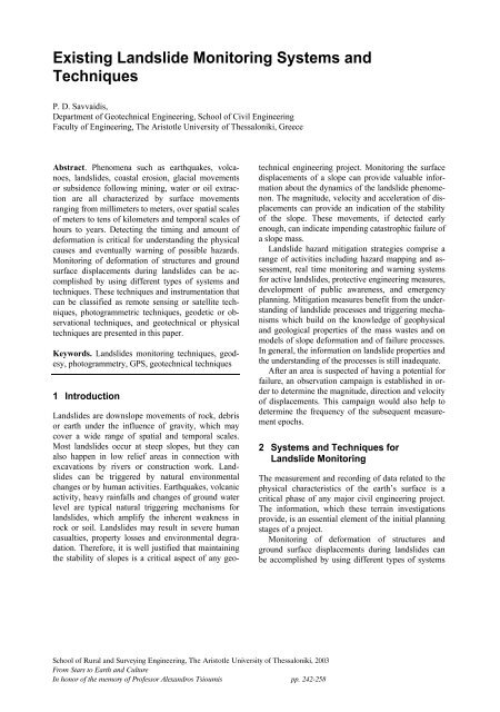
conditions, <strong>and</strong> the possible presence of buried valleys.Correlating these factors to geology <strong>and</strong> topography<strong>and</strong> using local experience in region make itpossible to rate the susceptibility of various areas tosliding.The combination of aerial photography <strong>and</strong> infraredimagery provides a more accurate <strong>and</strong> completeportrayal of terrain conditions than that obtained fromeither system alone. Infrared imagery provides typesof information that is valuable for evaluating existingl<strong>and</strong>slide <strong>and</strong> l<strong>and</strong>slide - susceptible terrain, like surface<strong>and</strong> near - surface moisture <strong>and</strong> drainage conditions,indication of the presence of massive bedrockor bedrock at shallow depths, distinction betweenloose materials that are present on steep slopes <strong>and</strong>are susceptible to l<strong>and</strong>slides etc.In addition to optical sensors, which have beenused to obtain morphological, lithological <strong>and</strong> structuralproperties of l<strong>and</strong>slides, powerful tools for l<strong>and</strong>slidemonitoring have been developed in recent yearsbased on imaging radar (Synthetic Aperture Radar,SAR). Also, the technique of spaceborne InterferometricSynthetic Aperture Radar (InSAR) providesan excellent means of observing deformation overbroad areas. InSAR has proven to be a powerful toolto characterize large-scale deformation associatedwith active faults. It also can resolve small-scale deformationfeatures such as shallow creep, postseismic<strong>and</strong> interseismic deformation. And it is an ideal toolfor measuring l<strong>and</strong> subsidence <strong>and</strong> improving digitalterrain models.InSAR offers the possibility to map <strong>and</strong> monitorthe displacement of slopes <strong>and</strong> even of individual objects.Applications have been demonstrated in differentplaces, based on ERS data, revealing satisfactoryaccuracy for displacement analysis <strong>and</strong> time seriesof motion over many years. Major constraints forthe application result from vegetation <strong>and</strong> from unsuitableorientation of a slope relative to the radarillumination. The problem of vegetation can be partlyovercome by the PS technique, if stable objects suchas houses etc. are located within these areas. In comparisonto ground based GPS or geodetic surveys,InSAR provides the complete motion field of a slope,<strong>and</strong> is also an economic means for detecting <strong>and</strong> analyzingunstable slopes over large areas.Space data are important because of the large spatialcoverage <strong>and</strong> the repeat observation capabilities. Thisis important for l<strong>and</strong>slide inventory maps from regionalto national scales because of the lower coststhan conventional measurements <strong>and</strong> the actuality ofthe data. Particularly in remote areas, the informationavailable from conventional sources is far from satisfactory.In addition, spaceborne InSAR capabilitiesare unique for providing repeat observations of surfacemotion over large areas at modest costs. Digitalelevation data from space are also of interest for l<strong>and</strong>slidecharacterization, where the accuracy of the presentsatellite systems (microwave or optical) is adequate,though improvements are desirable for smallscalel<strong>and</strong>slides.SAR satellites (ERS, Radarsat-1) show excellentcapabilities for monitoring surface motion with highaccuracy. The InSAR capabilities will be continued<strong>and</strong> even improved with ASAR on ENVISAT <strong>and</strong>Radarsat-2, TerraSAR etc.). In addition, InSAR is ofinterest for topographic mapping. High spatial resolutionoptical sensors data, (Ikonos, L<strong>and</strong>sat, SPOT etc.)provide useful information for l<strong>and</strong>slide inventorymapping <strong>and</strong> damage assessment.For monitoring the motion of active l<strong>and</strong>slidesground-based optical systems (video cameras) areused, but they have limitations in case of fog, rain <strong>and</strong>darkness. Recently new ground-based remote sensingsystems have been developed <strong>and</strong> tested successfully(Laser-scanners, SAR interferometry).Three-dimensional laser scanning systems (fig. 1)are currently used in high accuracy, small-scale industrialmetrology applications as well as for airbornemapping. Metrology applications can be found in theautomobile <strong>and</strong> aircraft assembly industries, as wellas in space-borne measurement. Several terrestriallaser-imaging systems have been released. Thesetypes of imaging system provide a user with a denseset of three-dimensional vectors to unknown pointsrelative to the scanner location. Given the volume ofpoints <strong>and</strong> high sampling frequency, laser-imagingsystems offer an unprecedented density of geospatialinformation coverage. For this reason, there is enormouspotential for use of this instrumentation inmonitoring applications where such dense data setscould provide great insight into the nature of structuraldeformations.Another important application of Earth observationdata is the generation of digital elevation models(DEMs), which is basic information for the characterizationof slopes <strong>and</strong> for numerical modeling ofmass waste processes. Data sources are optical stereoimages with high spatial resolution <strong>and</strong> InSAR.– 244 –
offers the advantage of cloud penetration, which is anadvantage for l<strong>and</strong>slides occurring during adverseweather or in connection with volcanic eruptions.The use of laser scanning for large scale (i.e.,greater than a few meters in range) ground-basedmeasurement operations is still at the research <strong>and</strong>development stage for terrestrial monitoring. It shouldalso be stressed that remote sensing is only an aid toengineering investigations, proving information whichis complementary to that obtained from other observationtechniques, field measurements, site visits <strong>and</strong>existing sources of data such as maps <strong>and</strong> projectsreports.2.2 Photogrammetric techniques forl<strong>and</strong>slide monitoringFig. 1. Laser 3D scannersRegarding real time monitoring of l<strong>and</strong>slides thatrepresent a risk, the capabilities of Earth observationfrom space is limited because of the repeat observationintervals. Accurate measurements of surface motion<strong>and</strong> its temporal changes, as provided by InSAR,are of significance. Depending on the repeat orbit <strong>and</strong>pointing capability of the sensor, repeat intervals of afew days can be achieved which is suitable only forthe observation of slow motion. In case of fastermovements ground-based installations are needed.Earth observation sensors are able to provide informationfor l<strong>and</strong>slide damage assessment. In orderto contribute to relief operations, high temporal <strong>and</strong>high spatial resolution is needed. In principle this canbe achieved by sensors with sideways pointing capabilities,but the repeat observation intervals of thepresent satellites are not yet fully satisfactory. Opticalsensors <strong>and</strong> SAR are suitable for this task, where SARPhotogrammetric techniques have been extensivelyused in determining ground movements in groundsubsidence studies in mining areas, <strong>and</strong> terrestrialphotogrammetry has been used in monitoring of engineeringstructures. The main advantages of usingphotogrammetry are the reduced time of fieldwork;simultaneous three-dimensional coordinates; <strong>and</strong> inprinciple an unlimited number of points can bemonitored. The accuracy of photogrammetric pointposition determination has been much improved inlast years, which makes it attractive for high accuracydeformation measurements.The interpretation of aerial photography has provento be an effective technique for recognizing <strong>and</strong> delineatingl<strong>and</strong>slides. It is an effective technique forrecognizing <strong>and</strong> delineating the three-dimensionaloverview of the terrain from which the interrelationsof photography, drainage, surface cover, geologymaterials, <strong>and</strong> human activities on the l<strong>and</strong>scape canbe viewed <strong>and</strong> evaluated.Aerial photographs present an overall perspectiveof a large area <strong>and</strong> boundaries of existing slides canreadily be delineated on aerial photographs. Surface<strong>and</strong> near-surface drainage channels can be traced.Important relations in drainage, topography <strong>and</strong> othernatural <strong>and</strong> man-made elements that seldom are correlatedproperly on the ground become obvious onphotographs. Furthermore, soil <strong>and</strong> rock formationscan be seen <strong>and</strong> evaluated in their undisturbed state.Recent photographs can be compared with old ones toexamine the progressive development of slides <strong>and</strong>aerial photographs can be studied at any time, in anyplace <strong>and</strong> person.– 245 –
Terrestrial photogrammetry <strong>and</strong> ground-basedphotography is also being used for local-scale l<strong>and</strong>slidemonitoring. Sites that are too steep or too smallto be confidently viewed from the air lend themselvesto study on the ground, albeit at a distance. Terrestrialphotogrammetry can effectively be used at unsafe orinaccessible sites, as road cuttings <strong>and</strong> l<strong>and</strong>slides.Special cameras with minimized optical <strong>and</strong> filmdistortions must be used in accuracy photogrammetry.Cameras combined with theodolites (phototheodolites),or stereocameras have found many applicationsin terrestrial engineering surveys includingmapping <strong>and</strong> volume determination of undergroundexcavations <strong>and</strong> profiling of tunnels. The accuracy ofphotogrammetric positioning with special camerasdepends mainly on the accuracy of the determinationof the image coordinates <strong>and</strong> the scale of the photographs.Using a camera with f = 100 mm, at a distanceS = 100 m, with the accuracy of the image coordinatesof 10 µm, the coordinates of the object points can bedetermined with the accuracy of 10 mm. Special largeformat cameras with long focal length are used inclose range industrial applications of high accuracy.They can give sub-millimeter accuracy in digitizingobjects up to several tens of meters away.Recently, solid-state cameras with CCD (chargecouple device) sensors have become available forclose range photogrammetry in static as well as indynamic applications. Continuous monitoring withreal time photogrammetry becomes possible with thenew developments in CCD cameras <strong>and</strong> digital imageprocessing techniques.As with aerial photographs, the image can bemeasured photogrammetrically, to yield quantitativedata, or interpreted for geotechnical information, orboth. The technique has advantages over conventionalsurveying methods if site access or time available tocomplete the survey is limited, or when changes needto be monitored over a long period of time. In terrestrialtechniques photographs can be taken over a periodof time to record changes in the l<strong>and</strong>scape in amore or less convenient way. This is not the case,though, with aerial photographs where temporal coverageis difficult to be achieved in a cost-effectiveway.2.3 Ground-based geodetic techniques forl<strong>and</strong>slide monitoringConventional ground-based geodetic techniques havebeen used for deformation monitoring of structures<strong>and</strong> l<strong>and</strong>slides. Two basic methods for the design of adeformation survey can be used:1. A horizontal or vertical control network is establishedin the area under investigation withcontrol points located in the deforming region.2. Total station instruments are used to measureangles <strong>and</strong> distances to target-prisms located onthe moving mass.In both cases the aim is the computation of targetpointcoordinates <strong>and</strong>/or heights for each measurementepoch. From the comparison of these coordinates/heights,after all proper statistical <strong>and</strong> reliabilitytests, the horizontal <strong>and</strong>/or vertical displacement vectorsof each control point can be determined.2.3.1 Triangulation <strong>and</strong> trilaterationhorizontal control networksIn triangulation <strong>and</strong> trilateration networks angles/directions <strong>and</strong> distances are measured with the properinstrumentation. Manually operated theodolites havebeen traditionally used for angle measurement in highaccuracy deformation surveying. Distances aremeasured using manually operated electronic distancemeasurement (EDM) instruments:a. Electronic theodolites. Over the last two decades,the technological progress in angle measurements hasbeen mainly in the automation of the readout systemsof the horizontal <strong>and</strong> vertical circles of the theodolites(fig. 2). Various, mainly photo-electronic, scanningsystems of coded circles with an automatic digitaldisplay <strong>and</strong> transfer of the readout to electronic datacollectors or computers have replaced the opticalreadout systems. As far as accuracy is concerned,electronic theodolites have not brought any drasticimprovements in comparison with accuracy opticaltheodolites. Atmospheric refraction is a particulardanger to any optical measurements, particularlywhere the line-of sight lies close to obstructions.b. Electronic Distance Measurement (EDM) Instruments.Short range (several kilometers), electro-opticalEDM instruments with visible or near infraredcontinuous radiation are used widely in engineeringsurveys. The accuracy (st<strong>and</strong>ard deviation) of EDMinstruments is expressed in a general form as:s = ± (a + bS)where "a" contains errors of the phase measurement<strong>and</strong> calibration errors of the so-called zero correction(additive constant of the instrument <strong>and</strong> of the reflec-– 246 –
tor), while the value of "b" represents a scale errordue to the uncertainties in the determination of therefractive index <strong>and</strong> errors in the calibration of themodulation frequency. Typically, the value of "a"ranges from 3 to 5 mm. In the highest accuracy EDMinstruments, the "a" value is 0.2 mm to 0.5 mm basedon a high modulation frequency <strong>and</strong> high resolutionof the phase measurements in those instruments. Onerecently developed engineering survey instrument isLeica DI2002 that offers a st<strong>and</strong>ard deviation of 1 mmover short distances. Over distances longer than a fewhundred meters, however, the prevailing error in allEDM instruments is due to refraction problems duringtheir propagation in the atmosphere. It is interesting toobserve that the production of high accuracy EDMinstruments (e.g. the Mekometer 5000) was discontinueddue to a small dem<strong>and</strong> <strong>and</strong> an extremely highcost.Fig. 2. Leica TM5100A high precision electronic theodolitec. Dual frequency instruments. Only a few units of adual frequency instrument (Terrameter LDM2 byTerra Technology) are available around the world.They are not really user-friendly in use but st<strong>and</strong>arddeviations of ± 0.1 mm ± 0.1 ppm may be achievedwith them. Research in the development of new dualfrequency instruments is in progress.d. Three-dimensional positioning systems. Two ormore electronic theodolites linked to a PC computercreate a three-dimensional (3D) (positioning) systemwith real-time calculations of the coordinates. Thesystems are used for the highest accuracy positioning<strong>and</strong> deformation monitoring surveys over small areasor for measurements for industrial applications. LeicaTMS <strong>and</strong> UPM400 (Geotronics, Sweden) are examplesof such systems. Positions (x, y, <strong>and</strong> z) of targetsat distances up to ten meters away may be determinedwith st<strong>and</strong>ard deviations smaller than 0.05 millimeters.These systems can be used for l<strong>and</strong>slide monitoring.In this case high accuracy theodolites measurehorizontal <strong>and</strong> vertical angles to targets on the areaunder consideration. St<strong>and</strong>ard deviations dependamong others upon the accuracy of the instrumentsused but can be kept in low values.2.3.2 Vertical control networks <strong>and</strong> heightdeterminationThe traditional technique for height determination isdifferential leveling. It provides height differencemeasurements between a series of benchmarks. Verticalpositions can be determined to very high accuracy(± 0.1 - 1 mm) over short distances (10-100's of meters)using accuracy levels. Two major classes of accuracylevels commonly used for making deformationmeasurements are automatic levels <strong>and</strong> digital levels:a. Automatic levels. The old method of geometricalleveling with horizontal lines of sight is still the mostreliable <strong>and</strong> accurate, though slow, surveying method.With high magnification leveling instruments,equipped with the parallel glass plate micrometer <strong>and</strong>with invar graduated rods, a st<strong>and</strong>ard deviationsmaller than 0.1 mm per set-up may be achieved inheight difference determination with balanced lines ofsight not exceeding 20 meters. In leveling over longdistances (with a number of instrument set-ups) ast<strong>and</strong>ard deviation of 1 mm per kilometer may beachieved in flat terrain.b. Digital levels. The digital automatic leveling systemswith height <strong>and</strong> distance readout from encodedleveling rods have considerably increased the speed ofleveling (fig. 3). There are several contradictory remarkson their performance as high accuracy levels<strong>and</strong> some improvements are expected to be introducedby the manufacturers but they can effectively be usedin l<strong>and</strong>slide monitoring if geodetic leveling is selectedas the most suitable technique for height determination.c. Zenith angle methods. High accuracy electronictheodolites <strong>and</strong> EDM equipment allow for the replacementof geodetic leveling with more economicaltrigonometric height measurements. An accuracybetter than 1 mm may be achieved in height differencedetermination between two targets 200 m apartusing accuracy electronic theodolites for vertical an-– 247 –
gle measurements <strong>and</strong> an EDM instrument. This techniqueis especially more economical than conventionalleveling in hilly terrain, <strong>and</strong> in all situationswhere large height differences between survey stationsare involved. It can be used in l<strong>and</strong>slide monitoringinstead of geodetic leveling. The refractionerror is still the major problem with increasing theaccuracy of trigonometric leveling.Fig. 3. Leica NA 2003 automated digital level <strong>and</strong> section frombar-coded invar level rodd. GPS measurements. Height differences can also becomputed with the use of GPS receivers. Height determinationwith GPS has somewhat worse accuracythan horizontal position. GPS control networks havebeen for l<strong>and</strong> subsistence measurements. It must benoted that GPS provides geometrical height differencesthat must be transformed into orthometric inorder to be compatible to measurements with theother techniques.2.3.3 Total station instruments for l<strong>and</strong>slidemonitoringIn the past, any electronic theodolite linked to anEDM instrument <strong>and</strong> to a computer was considered tobe a total surveying station which allows for a simultaneousmeasurement of the three basic positioningparameters, distance, horizontal direction, <strong>and</strong> verticalangle, from which relative horizontal <strong>and</strong> vertical positionsof the observed points can be determined directlyin the field. The last years, the manufacturers ofsurveying equipment produce integrated total stations.Different models of total stations vary in accuracy,range, sophistication of the automatic data collection,<strong>and</strong> possibilities for on-line data processing.The launch of the motorized theodolites (fig. 4)known also as surveying robots or robotic surveyingsystems introduced the possibility of collecting 3Dpositional information for automatic deformationmonitoring. They can track a moving target <strong>and</strong> makeautomatic measurements of angles <strong>and</strong> distances tothe target in motion. These instruments can makemeasurements at data rates up to 1 Hz <strong>and</strong> can operateautonomously once “locked” to the target that hasbeen manually set by an operator. Current technologyprovides total stations that are able to measure angleswith an accuracy of ± 0.15 mgon, <strong>and</strong> distances withan accuracy of ±1mm + 1ppm to a range of 3,500 m.Total stations allow the measurement of many pointswith prism-targets on the surface being monitoredwithin a short period of time. Using Automatic TargetRecognition (ATR) technology each prism can befound <strong>and</strong> its center identified to provide precise targetpointing. Such technologies are ideal for preciseapplications where the removal of error sources isdesired. The ATR approach used by Leica uses nonactiveprisms <strong>and</strong> hence does not require a powersource at each prism, reducing the cost of each prisminstallation.Early automated vision systems were installed inaccuracy theodolites by the 1980's. Its operating componentsconsisted of an external video camera imagingsystem <strong>and</strong> a separate servomotor drive. Modernsystems are more sophisticated being packaged internally<strong>and</strong> having an active beam sensing capability.An emitted IR signal is transmitted to the prism thatpassively reflects the signal back to the instrument.The return spot is imaged on a high-resolution (500 x500) pixel CCD array. The centroid is located in relationto the current position of the optical cross-hairs(reticule). A series of targets are sighted so the instrumentcan be trained to their location at least once.With the approximate coordinates of each target prismstored in memory, the ATR system can then take overthe pointing, reading, <strong>and</strong> measuring functions completelywithin the instrument. The user can programtarget search radius, data rejection thresholds, <strong>and</strong>other controls into the operating menus.The first commercial motorized total station wasGeorobot. Recent advanced systems include for example,the Geodimeter 140 SMS (Slope <strong>Monitoring</strong>System) <strong>and</strong> the Leica APS <strong>and</strong> Georobot III systemsbased on the motorized TM 3000 series of Leicaelectronic theodolites linked together with any DIseries of EDM. These can be programmed for se-– 248 –
quential self-pointing to a set of prism targets at predeterminedtime intervals, can measure distances <strong>and</strong>horizontal <strong>and</strong> vertical angles, <strong>and</strong> can transmit thedata to the office computer via a telemetry link.Similar systems are being developed by other manufacturersof surveying equipment. The robotic systemshave found many applications, particularly in monitoringhigh walls in open pit mining <strong>and</strong> in slope stabilitystudies. Generally, the accuracy of directionmeasurements with the self-pointing computerizedtheodolites is worse than the measurements withmanual pointing.Fig. 4. TCA2003 <strong>and</strong> TDM5005 motorized total stationsAs with any observational technique, total stationsystems have both advantages <strong>and</strong> disadvantages associatedwith their use. The main advantage of usingtotal station instruments is that they provide threedimensionalcoordinate information of the pointsmeasured. One of the disadvantages is the requirementto have an unobstructed line-of-sight betweenthe instrument <strong>and</strong> the targeting prism. Another disadvantageis that vertical refraction errors can reducethe accuracy of the height information that may beobtained from the total station measurements.Recently, a few models of EDM instruments with ashort pulse transmission <strong>and</strong> direct measurement ofthe propagation time have become available. Theseinstruments, having a high energy transmitted signal,may be used without reflectors to measure short distances(up to 200 m) directly to walls or natural flatsurfaces with an accuracy of about 10 millimeters. Anexample is the Leica DIOR 3002 EDM instrument.Reflectorless total stations have also been introduced<strong>and</strong> can be used in some cases for l<strong>and</strong>slide monitoring.However, the accuracy of distance measurementdepends upon the repeatability <strong>and</strong> reflective propertiesof the targeting surface or object.It must be pointed out that electronic total station instrumentshave largely replaced older instruments <strong>and</strong>techniques, such as theodolites <strong>and</strong> EDM instrumentsin many surveying applications.2.4 Satellite-based geodetic techniques forl<strong>and</strong>slide monitoringThe Global Positioning System (GPS) can be used asan alternative surveying tool to assist in geotechnicalevaluations of steep slopes by providing 3D coordinatetime series of displacements at discrete points onthe sliding surface (fig. 5). Current GPS positioningtechniques for monitoring applications typically includethe use of either episodic techniques for smallscaleprojects or continuous monitoring for regionalscale projects. Each of these techniques has associatedtrade-offs between system installation <strong>and</strong> maintenancecosts, <strong>and</strong> the quality of the resulting coordinatetime-series.GPS positioning is based on measuring the transittime of radio signals emitted by orbiting satellites. Fora receiver to compute its st<strong>and</strong>-alone position, it mustbe in view of at least four satellites. Code Phase Positioningis widely used in navigation <strong>and</strong> low accuracytracking applications, <strong>and</strong> relies on the measurementof the modulated GPS signal code phase, which exhibitsa resolution of about 1m. The measurement isaffected by several perturbations, which bring theachievable accuracy to about 5-10m.GPS offers advantages over conventional terrestrialmethods. Visibility among stations is not strictly necessary,allowing greater flexibility in the selection ofstation locations than for terrestrial geodetic surveys.Measurements can be taken during night or day, undervarying weather conditions, which makes GPS measurementseconomical, especially when multiple receiverscan be deployed on the deforming mass duringthe survey.The accuracy of GPS relative positioning dependson the distribution (positional geometry) of the observedsatellites <strong>and</strong> on the quality of the observations.Several major sources of error contaminatingthe GPS measurements are:1. Signal propagation errors--tropospheric <strong>and</strong> ionosphericrefraction, <strong>and</strong> signal multipath2. Receiver related errors--antenna phase center variation,<strong>and</strong> receiver system noise– 249 –
3. Satellite related errors--such as orbit errors <strong>and</strong>bias in the fixed station coordinates.Experience with the use of GPS in various deformationstudies indicate that with the available technologythe accuracy of GPS relative positioning overareas of up to 50 km in diameter can be of the order of± 5 mm. Systematic measurement errors over shortdistances (up to a few hundred meters) are usuallynegligible <strong>and</strong> the horizontal components of the GPSbaselines can be determined with a st<strong>and</strong>ard deviationof 3 mm or even smaller. The accuracy of verticalcomponents of the baselines is 1.5 to 2.5 times worsethan the horizontal components. Recent improvementsto the software for the GPS data processingallow for an almost real time determination ofchanges in the positions of GPS stations.Fig. 5. GPS measurements in a l<strong>and</strong>slide areaDifferent types of errors affect GPS relative positioningin different ways. Some of the errors mayhave a systematic effect on the measured baselinesproducing scale errors <strong>and</strong> rotations. Due to thechangeable geometrical distribution of the satellites<strong>and</strong> the resulting changeable systematic effects of theobservation errors, repeated GPS surveys for the purposeof monitoring deformations can affect deriveddeformation parameters (up to a few ppm). Attentionto the systematic influences should be made when aGPS network is established along the shore of a largebody of water <strong>and</strong> measurements are performed in ahot <strong>and</strong> humid climate. The solution for systematicparameters in a GPS network may be obtained by:1. Combining GPS surveys of some baselines (withdifferent orientation) with terrestrial surveys of acompatible or better precision.2. Establishing several points outside the deformablearea (fiducial stations), which would serveas reference points.These aspects must be considered when designingGPS networks for any engineering project. AlthoughGPS does not require the visibility among the observingstations, it requires an unobstructed view tothe satellites that limits the use of GPS only to reasonablyopen areas.When performing GPS based deformation surveys,the receiver used must be geodetic quality, multichannel,dual frequency, <strong>and</strong> capable of one seconddata sampling. The receiver should also be capable ofrecording the GPS carrier frequency, receiver clocktime, <strong>and</strong> signal strength for each data sample.Typically, a GPS receiver is required for each referencestation in the reference network. The samemodel receiver/antenna combination should be usedfor each setup. Preprocessing of GPS survey data, at aminimum, must include determination of the 3D coordinatedifferences <strong>and</strong> associated variance-covariancematrix in the 3D coordinate system for all baselinesobserved, <strong>and</strong> data screening to eliminate possibleoutliers.Other satellite-related positioning systems such asGLONASS <strong>and</strong> pseudolites have also been used fordeformation measurements but their application tolarge scale campaigns is still not possible. TheGLONASS system does not provide the level of operationalcapability needed for high precision deformationmonitoring. The new GALILEO satellite positioningsystem introduced by the European Union asa civil satellite system is still in the stage of design.2.4.1 Episodic GPS deformation monitoringGPS techniques are used to measure vectors in spaceamong the points of a control network. In order tocompute deformations, repeated GPS surveys must bedone (for example every few weeks or months). Acomparison of their results can give the observed displacementsof the network points. Static, rapid-staticor real-time kinematic GPS surveying techniques canbe used.Precise static positioning using carrier phase differentialGPS involves forming double differences toeliminate most errors common to both receivers, <strong>and</strong>integrating the measurement over time. The methodthus requires collecting <strong>and</strong> post processing a relativelylarge amount of data, a sufficient amount of– 250 –
computing resources, <strong>and</strong> is by definition non realtime.Real Time Kinematic GPS ( RTK GPS) delivers3D coordinates with an accuracy of ± (5mm + 2ppm)in real-time with a frequency as high as 0.2Hz.Equipment which provide the accuracy achievablewith RTK GPS <strong>and</strong> with the update rates that is possiblewith modern GPS receivers provide the idealsensor for monitoring “high” <strong>and</strong> “low” frequencymovements in structures (e.g. bridges <strong>and</strong> buildings)<strong>and</strong> l<strong>and</strong>slides.Another possibility is using the rapid static positioningtechnique. In this way, the time for the measurementsat each station is reduced to a few minutes.When using an episodic monitoring system thereare lower establishment costs, but there are certaindisadvantages as well. These may include:1. Discontinuous time series that does not alwaysallow the extraction of the trend of the deformationsfrom the noise existing within the observations.2. Poor systematic error modelling due to shortobservation times.3. Safety considerations for personnel re-enteringsite.Episodic GPS monitoring systems have less cost todeploy but require personnel costs throughout thelifetime of the measurement regime.2.4.2 Continuous operating GPS systemsGPS networks of regional scale have been establishedacross the tectonic zones at various tectonic plateboundaries. These networks form permanent arrays,which observe continuously GPS phase data mainlyfor geodynamical studies. In the local scale, continuousmonitoring GPS systems can be used for the detailedstudy of l<strong>and</strong>slide motions. The basic idea is toestablish a few GPS stations outside the l<strong>and</strong>slide areaas a reference frame. The GPS monitoring stations areestablished at critical points of the l<strong>and</strong>slide zone inorder to measure the l<strong>and</strong>slide motion at discretepoints. All GPS stations transmit the GPS data to amaster control station where the time series of themotions of the monitoring stations are continuouslycalculated thus providing the continuous monitoringof movements on the earths surface with a prescribedtracking rate. According to the software being usedthere can also be an alarm system activated when recordeddisplacements exceed a pre-determined value.Although that typically L1/L2 GPS receivers arebeing used, continuous operating systems comprisedof low-cost L1 frequency receivers have also been inoperation with promising results for l<strong>and</strong>slide monitoring.The actual method of communication betweenmeasurement stations <strong>and</strong> control station may differdepending on the geographic location <strong>and</strong> the specificrequirements of the monitoring project. Where a cellulartelephone infrastructure is available <strong>and</strong> the applicationis uncritical in both timing <strong>and</strong> securitylevel, a connection over a cellular modem is ideal.Examples are the long-term, weekly monitoring of al<strong>and</strong> subsidence, or the daily measurement of abreakwater protection structure. A UHF radio link is agood choice when the application is such that independencefrom existing telecommunication infrastructuresis desirable or essential. This may be thecase for l<strong>and</strong>slide or mudslide monitoring, where thesame or a possibly unrelated catastrophic event maycause overload or disruption of the cellular telephoneinfrastructure, thus rendering the monitoring <strong>and</strong> surveillancesystem unusable when its operation isneeded most. With a radio link, the cost of a singlecommunication is negligible compared to the cellularsolution, but the necessary equipment investment maybe higher when distances over several km must bebridged between the measurement site <strong>and</strong> the basestation, requiring the installation of radio relay stations.As a third possibility, data are made availablethrough Internet sites. In this way, all elements of amonitoring network may be accessed either locally orremotely from any part of the world. This eases remotediagnostics, as well as applications where morethan one network needs to be monitored from a centralizedlocation.The continuous operating GPS deformation monitoringsystems, CODMS, are capable to detect horizontall<strong>and</strong>slide motions with an accuracy of about ±2-3 mm in near real-time i.e. within a few minutes.The most important advantages for using continuousmonitoring permanent GPS:1. Multiple reference stations can be used.2. High accuracy can be achieved.3. Continuous time series is created for a completestudy of the phenomena.4. There is better systematic error modeling capability.5. There are no set up errors.6. Minimal user interaction.– 251 –
On the other h<strong>and</strong>, the method has high establishmentcosts. Often, the cost of installing <strong>and</strong> maintaininga network of GPS receivers that operate continuouslyprohibits the use of such systems.Continuous operating GPS systems can give a highlevel of coordinate precision that can enable the detectionof small deformations (in the order of few mmor cm) over long period of time (months or years).This is made possible because of the high temporaldensity of the resulting coordinate time-series.2.4.3 Multi-antenna GPS deformation monitoringsystemsA multi-antenna GPS deformation monitoring systemcan provide high precision GPS-derived coordinatesolutions of multiple monitoring points using only oneGPS receiver (fig. 6). This is achieved by samplingdata from a number of GPS antennas using a coaxialswitching device. This innovative approach to GPSdeformation monitoring reduces the amount of instrumentsrequired to measure at multiple locations onthe deforming region. As a result, the implementationcosts are kept low.The system consists of (at least) one GPS receiverconnected to a number of GPS antennas. A coaxialswitching device enables data from the antennas to besampled sequentially. A radio communication systemis used to transmit the raw GPS data from the remotestations to the master control station.Fig. 6. Multi-antenna GPS deformation monitoring systemThe system can be operated on an episodic or on acontinuous base. The results of the use of such systemswere very promising but the area covered is stillsmall due to the limits in the length of the connectioncables of the antennas to the receiver. A dedicatedradio system transmitting data from the antenna to thereceiver would enhance dramatically the efficiency ofthis technique for l<strong>and</strong>slide monitoring <strong>and</strong> other deformationapplications.2.5 Geotechnical techniques for l<strong>and</strong>slidemonitoringGeotechnical sensors are used extensively in themonitoring of structures. These sensors are oftenplaced within the structure <strong>and</strong> out of sight, howeverthey are never out of mind. During construction of thestructure geotechnical sensors of the desired type arecarefully chosen <strong>and</strong> placed at strategic locations toensure that adequate information is provided to verifydesign parameters, evaluate the performance of newtechnologies used in construction, verify <strong>and</strong> controlthe construction process <strong>and</strong> for subsequent deformationmonitoring.The main geotechnical sensors used for deformationmonitoring include; extensometers, inclinometers,piezometers, strain meters, pressure cells, geophones,tilt meters <strong>and</strong> crack meters. Most of geotechnicalsensors can either store the measured datainternally awaiting download, or the measurementscan be automatically logged to a connected computer.Connection to a computer offers a number of advantages(e.g. data stored at a remote location; ability tochange update rate of measurement data, whenchanges in measured values are detected; no need tovisit site to download data) <strong>and</strong> disadvantages (e.g.transfer media required between sensor <strong>and</strong> computer,for example cable/radio/GSM; loss of data possible iftransfer media is not operating <strong>and</strong> internal storage isnot activated).Geotechnical sensors provide measurements thatare often essential in deformation monitoring. An additionalsensor category that completes the portfolioof deformation monitoring sensors, that provide theirown analyzable measurements or measurements tocalibrate additional sensors, is meteorological sensors.The principal techniques/instrumentation will bebriefly discussed below.2.5.1 InclinometersThey are instruments installed in boreholes drilledwithin the l<strong>and</strong>slide mass. They measure the curvatureof initially straight boreholes, thus detecting anychange in inclination of the borehole casing. They canhelp for the determination of slip surfaces or zones of– 252 –
movement <strong>and</strong> they reveal the depth of the failureplane(s).This is typically accomplished with the help of agravity operated tilt sensor. There are many differentconfigurations of borehole inclinometers (fig. 7)available. They are distinguished according to themeasurement sensors: vibrating wire transducers, differentialwire transducers, servo-accelerometers <strong>and</strong>gravity activated electrolyte cells.The accuracy attainable can be of the order of ±0.02 mm over a baseline length of 3 m. The main disadvantageof this type of instrument is that curvatureis only observed in one axis.2.5.2 ExtensometersVarious types of instruments, mainly mechanical <strong>and</strong>electromechanical, are used to measure changes indistance in order to determine compaction or upheavalof soil, convergence of walls in engineering structures<strong>and</strong> underground excavations, strain in rocks <strong>and</strong> inman-made materials, separation between rock layersaround driven tunnels, slope stability, <strong>and</strong> movementsof structures with respect to the foundation rocks.Depending on its particular application, the same instrumentmay be named an extensometer, strain meter,convergencemeter, or fissuremeter. The variousinstruments differ from each other by the method oflinking together the points between which the changein the distance is to be determined <strong>and</strong> the kind ofsensor employed to measure the change. The links inmost instruments are mechanical, such as wires, rods,or tubes. The sensors usually are mechanical, such ascalipers or dial gauges. In order to adapt them toautomatic <strong>and</strong> continuous data recording, electrictransducers can be employed using, for instance, linearpotentiometers, differential transformers, <strong>and</strong> selfinductanceresonant circuits.Extensometers can measure the axial displacementbetween a number of reference points in the samemeasurements axis. They can be installed within aborehole or on the slope surface (fig. 8). The wireextensometer is widely used typically measuringbaselines of up to 80 m in length with a accuracy of ±0.3 mm per 30 m. The actual accuracy depends on thetemperature corrections <strong>and</strong> on the quality of the installationof the extensometer. Maintaining a constanttension throughout the use of the wire extensometer isvery important. Steel, invar, aluminum, or fiberglasswires of various lengths, together with sensors of theirmovements, may be used depending on the application.The main disadvantage of this type of instrument isthat the one-dimensional displacement vector cannotmeasure out of line displacements. The extensometermust also be anchored outside the deformation zone ifabsolute displacements must be recorded, which canbe a problem if the deforming area is large.To determine the total strain tensor in a plane (twonormal strains <strong>and</strong> one shearing), a minimum of threeextensometers must be installed in three different directions.A new development in the measurements of extensions<strong>and</strong> changes in crack-width employs a fullyautomatic extensometer that utilizes the principle ofelectro-optical distance measurements within fiberoptic conduits. The changes in length of the fiber opticsensors are sensed electro-optically <strong>and</strong> are computercontrolled.2.5.3 PiezometersMany l<strong>and</strong>slides are triggered by slope saturationfollowing heavy rainfall. Measurement of pore waterpressures <strong>and</strong> piezometric levels form an importantpart of slope stability analysis. Threshold levels canbe defined to provide early warning of conditions thatmay lead to catastrophic failure.Fig. 7. Inclinometer– 253 –
2.5.4 GeophonesThey are devices that can measure vibration associatedwith movement. They are useful as early warningsystems (fig. 10). They can detect l<strong>and</strong>slides on thebasis of frequency composition, amplitude, <strong>and</strong> durationof the vibration signal.Fig. 8. An extensometer installed on the slope surfacePiezometers measure the pore pressure of groundwaterwithin a geological structure, thus giving anindication of the build up of stresses <strong>and</strong> strainswithin the rock mass. Common types of borehole piezometersare the vibrating wire, pneumatic <strong>and</strong> st<strong>and</strong>pipepiezometers.The vibrating wire piezometers (fig. 9) convertwater pressure to a frequency signal via a diaphragm,a tensioned steel wire, <strong>and</strong> an electro-magnetic coil.So, a change in pressure on the diaphragm causes achange in tension of the wire that can be recorded.They are reliable, accurate <strong>and</strong> can measure rapidchanges in pore water pressure. The data collectioncan be automated but they have a rather high cost.The other types of piezometers are simple devices,rugged, inexpensive <strong>and</strong> popular. On the other h<strong>and</strong>they cannot measure rapid changes in the piezometrichead <strong>and</strong> need to manually measure the pore pressure.2.5.5 TiltmetersThe measurement of tilt is usually understood as thedetermination of a deviation from the horizontalplane, while inclination is interpreted as a deviationfrom the vertical. There are many reasonably pricedmodels of various liquid, electrolytic, vibrating wire,<strong>and</strong> pendulum type tiltmeters that satisfy most of theneeds of engineering surveys.They are instruments that can measure degrees ofrotation. They are based on electrolytic level sensors(fig. 11). They can be more sensitive than <strong>and</strong> areuseful on extremely slow moving rotational failures.Tiltmeters are used to determine the direction ofmovement, to delimit the areas of deformation <strong>and</strong> todetermine the mechanism of movement (e.g. slumpingor slope creep). They can also provide advancewarning of accelerated slide movement <strong>and</strong> quantifythe effectiveness of l<strong>and</strong>slide repairs.Fig. 10. An early l<strong>and</strong>slide warning system based on geophonesFig. 9. Sensor of a vibrating wire extensometerFig. 11. An electrolytic level sensor of a tiltmeter– 254 –
2.5.6 Crack metersCrack meters can be very useful tools in the early detectionof deforming mass movements. These devicesmeasure the displacement between two points on thesurface that are exhibiting signs of separation. Theycan be very simple <strong>and</strong> low-cost devices, so they areoften used as warning systems.3 Comparison of l<strong>and</strong>slide monitoringmethodsEach measurement technique has its own advantages<strong>and</strong> disadvantages. Remote sensing is a very helpfultechnique for regional ground displacement monitoringalthough the small scale of satellite imagery imposessome limitations. On the other h<strong>and</strong> the temporalcoverage is very good. Satellite or/<strong>and</strong> groundbasedInterferometric Synthetic Aperture Radar (In-SAR) techniques are capable of providing key informationfor monitoring of l<strong>and</strong>slides <strong>and</strong> other geologicalhazards. The value adding industry <strong>and</strong> researchlaboratories developed excellent tools for In-SAR analysis, which should be adapted for fully operationaluse <strong>and</strong> for integration with conventionalobservations <strong>and</strong> predictive models.InSAR <strong>and</strong> GPS techniques are complementary,<strong>and</strong> GPS can "calibrate" the InSAR errors. Hence theintegrated InSAR-GPS technique has the potential tomeasure deformations at sub-centimeter levels of precisionwith unprecedented spatial coverage. The developmentof such a system will result in a methodologybased on the optimum combination of InSAR <strong>and</strong>GPS technologies <strong>and</strong> is still under research.Aerial photos provide the base for local displacementcomputations but the temporal coverage is ratherpoor, making this technique useful for comparisonsover large periods of time. Terrestrial Photogrammetrycan also be used even for real-time monitoringwith the help of CCD sensors.Ground-based geodetic techniques, through a networkof points interconnected by angle <strong>and</strong>/or distancemeasurements, usually supply a sufficient redundancyof observations for the statistical evaluationof their quality <strong>and</strong> for a detection of errors. Theygive global information on the behavior of the deformingmass. Geotechnical measurements give verylocalized <strong>and</strong>, very frequently, locally disturbed informationwithout any check unless compared withsome other independent measurements. On the otherh<strong>and</strong>, geotechnical instruments are easier to adapt forautomatic <strong>and</strong> continuous monitoring than conventionalgeodetic instruments. Conventional terrestrialsurveys are labor intensive <strong>and</strong> require skillful observerskeeping the cost of monitoring campaignsrather high, while geotechnical instruments, once installed,require only infrequent checks on their performance.Geodetic surveys have traditionally beenused mainly for determining the absolute displacementsof selected points on the surface of the objectwith respect to some reference points that are assumedto be stable. Geotechnical measurements havemainly been used for relative deformation measurementswithin the deformable object <strong>and</strong> its surroundings.Measurements with traditional geodetic techniquesare done according to a periodic schedule, thus reducingthe ability to appropriately model the observedphenomena. Furthermore, on-site instruments mayrequire maintenance <strong>and</strong> cleaning, thus increasingsafety hazards to personnel re-entering potentiallyhazardous areas.Geodetic surveys with optical <strong>and</strong> electromagneticinstruments suffer from atmospheric refraction effects,which limit their positioning accuracy to about±2 mm for distances up to 500 m, but this value ofaccuracy can be adequate for most cases of l<strong>and</strong>slidemonitoring. Table 1 shows the typical accuracyclaimed by different monitoring techniques.There are cases, though, that geodetic instrumentationcan be used for l<strong>and</strong>slide monitoring in an automatedway, when using servo-driven robotic total stations.New developments in three-dimensional coordinatingsystems with electronic theodolites may providerelative positioning in almost real-time to an accuracyof ±0.05 mm over distances of several meters<strong>and</strong> ±1-2 mm over distances of several hundred meters.Satellite-based geodetic techniques, namely theGlobal Positioning System (GPS), if properly h<strong>and</strong>led,offers a few millimeters accuracy in differentialpositioning over several kilometers. In particular,GPS has the advantages of high data acquisition rate(typically up to 10 Hz) <strong>and</strong> autonomous operation.Also, using differential GPS techniques <strong>and</strong> the appropriateequipment, it can furnish position estimatesin real-time with centimeter-level accuracy. However,the disadvantage of GPS is that it requires a line-ofsightfrom the monitoring receivers to the transmittingsatellites <strong>and</strong> thus performs poorly in urban <strong>and</strong> fore-– 255 –
Table 1. Typical accuracy claimed by different deformation (l<strong>and</strong>slide) monitoring techniquesMethod of measurement Displacement parameter Distance between points Typical accuracyMetal tape or invar wire Distance < 30 m 0.5 mm / 30 mFixed wire extensometer Distance < 10 - 80 m 0.3 mm / 30 mInclinometer Elevation angle ± 10º ± (5-10 mm ± 1-2 ppm)Triangulation Trilateration Dx, Dy, Dh < 300 – 1000 m 2 – 10 mmTraverses Dx, Dy, Dh Variable 5 – 10 mmRobotic total station Dx, Dy, Dh < 100 m 1-3 mmPrecise geometriclevelingElectromagnetic DistanceMeasurementDh10 m100 m0.1 mm0.2 – 1 mm / KmDistance Variable ± (1-5 mm ± 1-5 ppm)Terrestrial Photogrammetry Dx, Dy, Dh < 100 m ± 10 mmAerial Photographs Dx, Dy, Dh Variable 10 cmGPS L1/L2 staticDx, Dy, Dh< 50 Km< 1-2 KM± (5 mm ± 2 ppm)± (1-3 mm ± 2ppm)RTK DGPS Dx, Dy, Dh Variable ± (5 mm ± 2 ppm)Continuous operating GPS Dx, Dy, Dh Variable ± 2 – 3 mmsted areas, <strong>and</strong> not at all indoors. GPS is replacingconventional terrestrial surveys in many deformationstudies <strong>and</strong>, particularly, in establishing the referencenetworks.4 ConclusionsEarth observation satellites <strong>and</strong> remote sensing areable to provide significant information for mappingthe extent <strong>and</strong> properties of l<strong>and</strong>slides. Some of thetechniques, for example the use of the new very highresolutionoptical satellite data for l<strong>and</strong>slide inventorymonitoring <strong>and</strong> hazard assessment, need to be furtherdeveloped. The powerful InSAR tools, which provideaccurate topography <strong>and</strong> motion maps <strong>and</strong> thus canmake significant contributions to the assessment <strong>and</strong>mitigation of l<strong>and</strong>slide hazards, are ready for transferto operations.Terrestrial laser scanning technology offers a rapidmeans of collecting dense sets of three-dimensionalpoint sets. For structural monitoring applications, laserscanning can be considered advantageous overgeodetic methods (e.g., surveying, GPS), which canonly sense deformation at a limited number of points,whereas a scanner can measure a deformation surface.Future work will concentrate on these aspects <strong>and</strong>integration of laser scanner data with measurementsfrom other sensors (e.g., GPS, digital cameras).Only few of the many monitoring techniques providea true 3D indication of the displacement vectorsof control points on the surface of the sliding area.GPS is an emerging technology that can be used toprovide a dense 3D time series to map the position<strong>and</strong> velocity of the deforming mass. Regional scalecontinuous operating GPS networks, such as thoseused for monitoring of tectonic motion can provide atemporally dense <strong>and</strong> precise time-series of 3D deformationdata at high installation <strong>and</strong> maintenancecosts. Episodic GPS monitoring techniques may be acheaper alternative but they result in poorer accuracy<strong>and</strong> reduced temporal density of the coordinate timeseries.Multi-antenna GPS monitoring systems canoffer a high level of accuracy at a reduced implementationcost but this technique has still to be developedfor larger scale l<strong>and</strong>slide monitoring. Geotechnicalmeasurements can also contribute to the study of al<strong>and</strong>slide phenomenon, alone or in combination withother monitoring techniques.In any case, the variability of spatial <strong>and</strong> temporalscales means that useful deformation monitoring mustrely not just on one measurement technique, but on asuitable combination of monitoring tools. In particular,advances in GPS technology mean that it is possi-– 256 –
le to deploy arrays of low-cost receivers or multiantennaGPS systems to monitor ground movementswith very high temporal resolution <strong>and</strong> moderate tolow spatial resolution, while satellite-based InSAR systemsare capable of very high spatial resolution butmoderate to low temporal resolution. The investigationon combining such datasets, most likely withadditional techniques such as robotic total stations,laser scanning, <strong>and</strong> geotechnical instruments for theefficient <strong>and</strong> reliable monitoring of real deformationalhazards is still in progress.ReferencesAshkenazi, V., Dodson A.H., Roberts G.W. (1998). RealTime <strong>Monitoring</strong> of Bridges by GPS. Proc. of XXI FIGInter. Congress, Commission 5: Positioning <strong>and</strong> Measurement,Brighton, UK, pp. 503-512.Baltsavias, E.P. (1999). Airborne Laser Scanning: BasicRelations <strong>and</strong> Formulas. ISPRS Journal of Photogrammetry<strong>and</strong> Remote Sensing, Vol. 54, No. 2-3, pp. 199-214.B<strong>and</strong>elas, A. <strong>and</strong> Savvaidis P. (1990). Deformation Measurementsof Technical Works <strong>and</strong> <strong>L<strong>and</strong>slide</strong>s with GeodeticMethods. Papageorgiou Publ. Co., Thessaloniki,257 p.Brunner, F.K. (2000). Continuous <strong>Monitoring</strong> of <strong>L<strong>and</strong>slide</strong>susing GPS: A Progress Report. In Proc. Of the GeophysicalAspects of Mass Movements, Bauer S.J <strong>and</strong> WeberF.K. (ed.), Austrian Academy of Sciences, Vienna, pp.75-88.Bock, Y., Williams S. (1997). Integrated Satellite Interferometryin Southern California. EOS Trans., AGU, 78(29),p.293.Bürgmann, R., Sukhatme J., Fielding E. (1998). SeismicPotential of the Northern Hayward Fault from SpacebasedSAR Interferometry <strong>and</strong> GPS Measurements. EOSTrans. AGU, 79 (45), 36.Celebi, M., Prescott W., Stein R., Hudnut K., Behr J., WilsonS. (1998). Structural <strong>Monitoring</strong> using GPS. Proc.11th Int. Tech. Meeting of the Satellite Division ION,Nashville, Tennessee, pp. 929-935.Corominas, J., Moya J., Lloret A., Gili J.A., Angeli M.G.,Pasuto A. <strong>and</strong> Silvano S. (2000). Measurement of <strong>L<strong>and</strong>slide</strong>Displacements using a Wire Extensometer. EngineeringGeology, Vol. 55, No. 55, pp. 149-166.Dai, L., Zhang J., Rizos C., Han S., Wang J. (2000). GPS<strong>and</strong> Pseudolite Intergration for Deformation <strong>Monitoring</strong>Applications. Proc. Of 13 th Inter. Technical Meeting ofthe Satellite Division of ION GPS-2000, Salt Lake City,pp. 1-7.De Heus, H. (1997). Subsidence <strong>Monitoring</strong> with GPS inthe Netherl<strong>and</strong>s. Proc. Of Inter. Symp. On CurrentCrustal Movement <strong>and</strong> Hazard Reduction, Wuhan,China, Seismological Press, pp. 184-195.Ding, X., Chen Y., Huang D., Zhu J., Tsakiri M., StewartM. (2000). Slope <strong>Monitoring</strong> using GPS – A Multi-antennaApproach. GPS World, Vol. 11, No. 3, pp. 52-55.Duffy, M.A., Hill C., Whitaker C., Chrzanowski A., LutesJ., Bastin G. (2001). An Automated <strong>and</strong> Intergrated<strong>Monitoring</strong> Program for Diamond Valley Lake in California.Proc. 10 th FIG Inter. Symp. On DeformationMeasurements, Orange, California, pp. K1-K23.Dunnicliff, J. (1988). Geotechnical Instrumentation formonitoring Field Performance, Wiley, New York, 608 p.Forward, T.A. (2002). Quasi-Continuous GPS Steep Slope<strong>Monitoring</strong>: A Multi-antenna Array Approach. PhD Dissertation,Curtin University of Technology, Australia.Fruneau, B., Achache J., Delacourt C. (1998). Observation<strong>and</strong> Modelling of the Saint-Etienne-de-Tinee <strong>L<strong>and</strong>slide</strong>using SAR Interferometry. Tectonophysics, 265, pp181-190.Gilli, J.A., Corominas J., Rius J. (2000). Using Global PositioningSystem <strong>Techniques</strong> in <strong>L<strong>and</strong>slide</strong> <strong>Monitoring</strong>.Engineering Geology, Vol. 55, pp. 167-192.Hofmann-Wellenhof, B., Lichtenegger H., Collins J. (1997).GPS Theory <strong>and</strong> Practice. Springer Verlag, Wien NewYork, 4 th revised edition), 389 p.Hudnut, K.W., Bock Y., Galetzka J.E., Webb F.H., YoungW.H. (2001). The Southern California Integrated GPSNetwork (SCIGN), Proc. 10 th FIG Inter. Symp. On DeformationMeasurements, Orange, California, pp. 129-148.Kälber, S., Jäger R. (2001). GPS-based Online Control <strong>and</strong>Alarm System (GOCA). Proc. 10 th FIG Inter. Symp. OnDeformation Measurements, Orange, California.Koivula, H., Ollikainen M., Poutanen M. (1998). Use of theFinnish Permanent GPS Network (FINNNET) in RegionalGPS Campaigns. Advances in Positioning <strong>and</strong>Reference Frames, Vol. 118, pp. 137-142.Leick, A. (1997). GPS Satellite Surveying. John Wiley <strong>and</strong>Sons, Inc., New York, 2 nd edition, 560 p.Lowry, A., McLeod R. (1997). PMos: A Real Time PreciseDGPS Continuous Deformation <strong>Monitoring</strong> System,SAGEM Australasia Pty Ltd.Ma E., Chen Y., Ding Z. (2001). <strong>Monitoring</strong> of Slope Stabilityby using Global Positioning System (GPS). Proc.Inter. Symp. On Kinematic <strong>Systems</strong> in Geodesy, Geomatics<strong>and</strong> Navigation – KIS2001, Alberta, pp. 298-310.Manetti L., Knecht A. (2000). Permanente und autonomeErdrutschüberwachung mit GPS. Mensuration, Photogrammetrie,Génie Rural, No. 7, Switzerl<strong>and</strong>.Ohkura, H. (1998). Application of SAR Data to <strong>Monitoring</strong>Earth Surface Changes <strong>and</strong> Displacement. Advances inSpace Research, Vol. 21, No. 3, pp. 485-492.– 257 –
Radovanovic, R.S., Teskey W.S., El-Sheimy N. (1999).Development of a GPS-based Deformation <strong>Monitoring</strong>System – Vol. III Multipath <strong>and</strong> Noise. Tech. Report, TheUniversity of Calgary.Radovanovic, R.S., Teskey W.S. (2001). Dynamic <strong>Monitoring</strong>of Deforming Structures: GPS versus RoboticTacheometry <strong>Systems</strong>. Proc. 10 th FIG Inter. Symp. OnDeformation Measurements, Orange, California.Reeves, B., Noon D., Stickley G., Longstaff D. (1997).<strong>Monitoring</strong> Rock Slope Deformation by Radar Interferometry.Proc. Workshop on Applications of Radioscience,The Australian Academy of Sciences, pp. 119-123.Rizos, C., Han S., Ge L., Chen H., Hatanaka Y., Abe K.(2000). Low-cost Densification of Permanent GPS Networksfor Natural Hazard Mitigation – First Tests onGSI’s GEONET Network. Earth, Planets <strong>and</strong> Space,Vol. 52, No. 10, pp. 867-871.Savvaidis, P. (1997). Transformation of Coordinates <strong>and</strong>GPS Measurements. G. Economides Publ., Thessaloniki,75 p.Savvaidis, P. <strong>and</strong> B<strong>and</strong>elas A. (1992). <strong>L<strong>and</strong>slide</strong>s <strong>Monitoring</strong>with Geodetic Methods in the Hellenic Area. In InstrumentalMethods for Investigation of Hazardous GeodynamicProcesses, Eds. G. Milev & H. Pelzer, pp. 166-175, Bulgarian Academy of Sciences, Sofia.U.S. Army Corps of Engineers (2002). Engineering <strong>and</strong>Design: Structural Deformation Surveying, Manual No.1110-2-1009, Washington.Wehr, A. <strong>and</strong> Lohr U. (1999). Airborne Laser Scanning –An Introduction <strong>and</strong> Overview, ISPRS Journal of Photogrammetry<strong>and</strong> Remote Sensing, Vol. 54, No. 2-3, pp. 68-82.– 258 –