Model-based virtual sensors for room heat metering and energy ...
Model-based virtual sensors for room heat metering and energy ...
Model-based virtual sensors for room heat metering and energy ...
You also want an ePaper? Increase the reach of your titles
YUMPU automatically turns print PDFs into web optimized ePapers that Google loves.
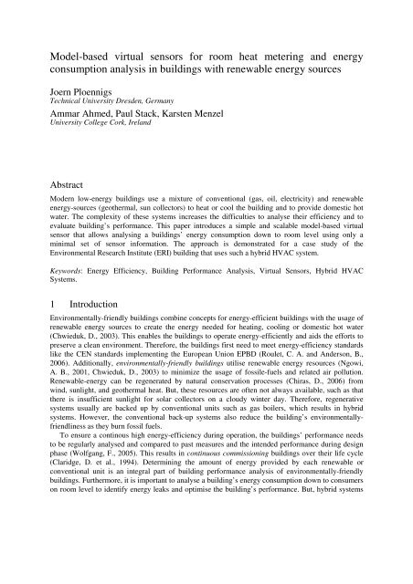
<strong>Model</strong>-<strong>based</strong> <strong>virtual</strong> <strong>sensors</strong> <strong>for</strong> <strong>room</strong> <strong>heat</strong> <strong>metering</strong> <strong>and</strong> <strong>energy</strong>consumption analysis in buildings with renewable <strong>energy</strong> sourcesJoern PloennigsTechnical University Dresden, GermanyAmmar Ahmed, Paul Stack, Karsten MenzelUniversity College Cork, Irel<strong>and</strong>AbstractModern low-<strong>energy</strong> buildings use a mixture of conventional (gas, oil, electricity) <strong>and</strong> renewable<strong>energy</strong>-sources (geothermal, sun collectors) to <strong>heat</strong> or cool the building <strong>and</strong> to provide domestic hotwater. The complexity of these systems increases the difficulties to analyse their efficiency <strong>and</strong> toevaluate building’s per<strong>for</strong>mance. This paper introduces a simple <strong>and</strong> scalable model-<strong>based</strong> <strong>virtual</strong>sensor that allows analysing a buildings’ <strong>energy</strong> consumption down to <strong>room</strong> level using only aminimal set of sensor in<strong>for</strong>mation. The approach is demonstrated <strong>for</strong> a case study of theEnvironmental Research Institute (ERI) building that uses such a hybrid HVAC system.Keywords: Energy Efficiency, Building Per<strong>for</strong>mance Analysis, Virtual Sensors, Hybrid HVACSystems.1 IntroductionEnvironmentally-friendly buildings combine concepts <strong>for</strong> <strong>energy</strong>-efficient buildings with the usage ofrenewable <strong>energy</strong> sources to create the <strong>energy</strong> needed <strong>for</strong> <strong>heat</strong>ing, cooling or domestic hot water(Chwieduk, D., 2003). This enables the buildings to operate <strong>energy</strong>-efficiently <strong>and</strong> aids the ef<strong>for</strong>ts topreserve a clean environment. There<strong>for</strong>e, the buildings first need to meet <strong>energy</strong>-efficiency st<strong>and</strong>ardslike the CEN st<strong>and</strong>ards implementing the European Union EPBD (Roulet, C. A. <strong>and</strong> Anderson, B.,2006). Additionally, environmentally-friendly buildings utilise renewable <strong>energy</strong> resources (Ngowi,A. B., 2001, Chwieduk, D., 2003) to minimize the usage of fossile-fuels <strong>and</strong> related air pollution.Renewable-<strong>energy</strong> can be regenerated by natural conservation processes (Chiras, D., 2006) fromwind, sunlight, <strong>and</strong> geothermal <strong>heat</strong>. But, these resources are often not always available, such as thatthere is insufficient sunlight <strong>for</strong> solar collectors on a cloudy winter day. There<strong>for</strong>e, regenerativesystems usually are backed up by conventional units such as gas boilers, which results in hybridsystems. However, the conventional back-up systems also reduce the building’s environmentallyfriendlinessas they burn fossil fuels.To ensure a continous high <strong>energy</strong>-efficiency during operation, the buildings’ per<strong>for</strong>mance needsto be regularly analysed <strong>and</strong> compared to past measures <strong>and</strong> the intended per<strong>for</strong>mance during designphase (Wolfgang, F., 2005). This results in continuous commissioning buildings over their life cycle(Claridge, D. et al., 1994). Determining the amount of <strong>energy</strong> provided by each renewable orconventional unit is an integral part of building per<strong>for</strong>mance analysis of environmentally-friendlybuildings. Furthermore, it is important to analyse a building’s <strong>energy</strong> consumption down to consumerson <strong>room</strong> level to identify <strong>energy</strong> leaks <strong>and</strong> optimise the building’s per<strong>for</strong>mance. But, hybrid systems
have also an increased complexity that renders it harder to analyse the building’s per<strong>for</strong>mance.Analysing a building’ <strong>energy</strong> consumption down to <strong>room</strong> level requires a high amount ofmeasurement equipment, such as <strong>sensors</strong> <strong>and</strong> meters in each single <strong>room</strong>. There<strong>for</strong>e, detailed buildingper<strong>for</strong>mance analysis is often hampered by high monitoring cost, <strong>and</strong> practitioners often requestalternative cost-efficient methods (Jagemar, L. <strong>and</strong> Olsson, D., 2007).This paper develops an estimation algorithm in Section 3 to analyse building’s <strong>energy</strong>consumption down to <strong>room</strong> level. The algorithm is adjustable in its in<strong>for</strong>mation intake to differentsensing <strong>and</strong> <strong>metering</strong> equipment available in a building, providing a flexible usage with roughestimations using few <strong>sensors</strong> to detailed computations using a high density sensing deployment. Thealgorithm can be used <strong>for</strong> offline data analysis <strong>and</strong> <strong>for</strong> online monitoring as a so-called <strong>virtual</strong> sensor(a model-<strong>based</strong> sensor) to estimate the <strong>heat</strong> flows in <strong>room</strong>s. Section 4 uses the algorithm’s output <strong>and</strong>compares it to the reached user com<strong>for</strong>t level to evaluate actions improving the building’s <strong>energy</strong>consumption. Both approaches provide a broad set of per<strong>for</strong>mance metrics to support buildingper<strong>for</strong>mance analysis, monitoring, <strong>and</strong> optimisation (Augenbroe, G. <strong>and</strong> Park, C.-S., 2005).The approach is validated using the ERI building as an existing low-<strong>energy</strong> building with a hybridHVAC system that is introduced in the next section.2 The Environmental Research Institute buildingThe Environmental Research Institute (ERI) is a 4500 m² low-<strong>energy</strong> building, located in the maincampus of University College Cork. The building is used as “Living Laboratory” by the In<strong>for</strong>maticsResearch Unit in Sustainable Engineering (IRUSE) <strong>and</strong> the Irish strategic research cluster ITOBO(ITOBO, 2007) to serve as a full-scale test bed <strong>for</strong> Intelligent Buildings demonstrating buildingper<strong>for</strong>mance concepts (Keane, M., 2005).CoolingCircuits P-12SolarThermalArrayHotWaterGas-firedBoilerHeat PumpUnderfloorHeatingPumpP-7MMeter HPMeter FH MUnderfloorHeatingManifoldsWater from culverttoriverFigure 1. High Level Schematic of the Mechanical System <strong>for</strong> the ERIThe building is equipped with a wireless sensor network of about 100 devices <strong>and</strong> a wiredBuilding Management System (BMS) system consisting of about 180 <strong>sensors</strong> <strong>and</strong> meters that monitorindoor <strong>and</strong> outdoor conditions. The ERI covers various HVAC requirements <strong>for</strong> laboratories, clean<strong>room</strong>s, cold stores, offices, open offices, <strong>and</strong> seminar <strong>room</strong>s used by multiple research groups frombiologist, chemist, engineers, <strong>and</strong> computer scientists.The building is <strong>heat</strong>ed by an under-floor <strong>heat</strong>ing system that is primarily supplied by a geothermal<strong>heat</strong> pump that taps into a water supply fed from a culvert running adjacent to a nearby river. Thewater is pre<strong>heat</strong>ed by <strong>heat</strong> recovered from the cold stores <strong>and</strong> <strong>heat</strong> generated by the solar thermalarray. The under-floor <strong>heat</strong>ing operates at a maximum temperature of 40ºC. A condensing gas boiler
is sized to act as a complete back-up system. The hot water is provided by an 84 m² solar thermalcollector array, where the rest of the requirement is provided by the boiler. See Figure 1 <strong>for</strong> aschematic of the mechanical system. The <strong>heat</strong> pump <strong>and</strong> boiler are separately controlled. Both havetimetable dependent set-points. They ensure that <strong>heat</strong>ing <strong>and</strong> domestic hot water are provided overworking hours.3 Estimating the <strong>room</strong> <strong>heat</strong> consumptionTo identify <strong>room</strong>s with unusual high <strong>heat</strong> usage the <strong>room</strong>’s <strong>heat</strong> consumption needs to be analysed.But, instead of installing <strong>heat</strong> meters in each <strong>room</strong> to measure the individual <strong>heat</strong> consumption, the<strong>room</strong>’s <strong>heat</strong> intake is estimated from the overall <strong>heat</strong> consumption of the underfloor <strong>heat</strong>ing system bycreating a <strong>virtual</strong> sensor model using knowledge about the <strong>room</strong> <strong>heat</strong>ing controls.In case of the ERI, each <strong>room</strong> has an individual temperature closed-control loop consisting of atemperature sensor, a decentralised controller <strong>and</strong> one to four on/off-valves operating separateunderfloor <strong>heat</strong>ing circuits. The temperature values are logged by the BMS. However, exactin<strong>for</strong>mation about the control values at the valves is not available in the BMS system. This is notuncommon as often only measurements are seen as important are logged, but it is the control valuesthat define the <strong>room</strong>’s <strong>and</strong> building’s <strong>heat</strong> consumption. The temperature closed-control loops areactivated all of the time in the ERI; but, the central <strong>heat</strong>ing system provides <strong>heat</strong> only at specific times.The basic assumption <strong>for</strong> the estimation is: that only these <strong>room</strong>s consume <strong>heat</strong>, which valves areopen <strong>and</strong> allow the hot water to circulate through the underfloor circuits. Let be defined as theabsolute <strong>heat</strong> flow of the underfloor <strong>heat</strong>ing system measured by the <strong>heat</strong> meter FH in Figure 1 in caseof the studied ERI. The <strong>heat</strong> flow is computed in the <strong>heat</strong> meter from the mass flow rate in thepipes <strong>and</strong> the temperature difference of the water going in <strong>and</strong> coming out of the underfloor circuits as · ; ; . The mass flow rate is controlled in case of the ERI by the centralunderfloor <strong>heat</strong>ing pump in Figure 1. The temperature difference depends on the <strong>heat</strong> consumption(flow) of the <strong>room</strong>s. Let be the <strong>heat</strong> flow of any <strong>room</strong> in the set of <strong>room</strong>s connected to the<strong>heat</strong>ing system. Assuming further that the underfloor <strong>heat</strong>ing system has no further losses beside inthe <strong>room</strong>s, then the overall <strong>heat</strong> flow in time step is the sum of all <strong>room</strong>’s flows <strong>and</strong> each <strong>room</strong> takes a percentaged share =/ in the overall consumption, thus · ; ; . (1)Due to the basic assumption, a <strong>room</strong>’s <strong>heat</strong> flow depends on the valve opening 0 100%.Which is insofar correct, as the valve opening limits the individual mass flows in the underflowcircuits of each <strong>room</strong>. Hence, if the valves in a <strong>room</strong> are closed ( = 0%) then the mass <strong>and</strong> <strong>heat</strong> flowas well as will be zero. But, if the valves are open ( > 0%) then the percentaged share can be inthe range of 0 1 as long ∑ 1 holds as given by eq. (1). Thus, considering the valveopening only allows determining the <strong>room</strong>s <strong>heat</strong>ed, but the share these <strong>room</strong>s take of the building’s<strong>heat</strong> consumption is still unknown.There<strong>for</strong>e, it is assumed that <strong>for</strong> each <strong>room</strong> a relative <strong>heat</strong>ing coefficient can be defined that is ameasurement of the <strong>room</strong>’s <strong>heat</strong>ing capacity in relation to other <strong>room</strong>s if all valves are fully open.This can be <strong>for</strong> example the sizes of the <strong>room</strong>’s underfloor <strong>heat</strong>ing circuits. Let the actual <strong>heat</strong>ingcoefficient of a building be further the sum of all <strong>room</strong>’s coefficients linearly depending ontheir valve opening such that · . (2)
Then, is a measurement of the building’s actual active <strong>heat</strong>ing capacity, i.e. if representsthe <strong>room</strong>’s underfloor <strong>heat</strong>ing circuits size then is the actual size of active circuits in time stepk. As is defined as the <strong>room</strong>’s <strong>heat</strong>ing capacity in relation to other <strong>room</strong>s, eq. (2) also allows toestimate the percentual share of a <strong>room</strong> in the overall <strong>heat</strong> flow from eq. (1) such that finally results · . (3) This equation (3) allows estimating the <strong>room</strong> <strong>heat</strong> flow from the relative <strong>heat</strong>ing capacity of a<strong>room</strong> in comparison to the others. In the named example of using the underfloor <strong>heat</strong>ing circuit size as it will mean that a <strong>room</strong> utilises the same proportion of the actual <strong>heat</strong> flow as his <strong>heat</strong>ing circuitsize is in relation to the building’s active circuits . The benefit of equation (3) is that it easilyscales to different available knowledge levels by modelling <strong>and</strong> adequately.The valve opening depends on the control values computed by the <strong>room</strong> temperaturecontroller. If a detailed model is necessary then the specific characteristic curves of the valves can beused. In case of the ERI, simple on/off-valves are used <strong>and</strong> it can be simplified that 0, 1.The relative <strong>heat</strong>ing coefficient of each <strong>room</strong> can be individually adapted to the availablein<strong>for</strong>mation about the building. In simple cases it can be set to the number of valves or radiators,which permits rough estimations. Better results provide the size of the underfloor <strong>heat</strong>ing system orradiators assuming that their size is proportional their <strong>heat</strong>ing capacity. For very precise results,detailed models of the <strong>heat</strong>ing system systems can be used that model also dynamic aspects such asthe dependence of the <strong>heat</strong> transfer on the temperature difference between the <strong>heat</strong>ing system <strong>and</strong><strong>room</strong> air temperature.The estimation in its basic <strong>for</strong>m in eq. (3) neglects any time delay behaviour in the <strong>heat</strong>ing systemsuch as the dead times of the water floating through the pipes as well as the delay behaviour of the<strong>heat</strong> transfer between the underfloor <strong>and</strong> the <strong>room</strong> air temperature. It assumes that the delay effectsare less relevant <strong>for</strong> the estimation considering the fact that large sampling intervals of 15 min arecommon in building per<strong>for</strong>mance analysis like in the ERI case. If the delay times are very large <strong>and</strong>not neglectable the equation (3) can be extended to an difference equation considering also pastcoefficients with <strong>and</strong> .Summarising, a buildings <strong>room</strong>’s <strong>heat</strong>ing consumption can be estimated in each time step by the following algorithm:(1) Compute the <strong>room</strong>’s control value <strong>and</strong> valve opening <strong>for</strong> each <strong>room</strong> .(2) Compute the building’s actual <strong>heat</strong>ing coefficient with eq. (2) from .(3) Estimate the <strong>room</strong>’s <strong>heat</strong> flow <strong>for</strong> each <strong>room</strong> via eq. (3) from , .The proposed algorithm uses the control value <strong>for</strong> each <strong>room</strong>’s individual <strong>heat</strong>ing control. Asin<strong>for</strong>mation about the control value is often not available like in the investigated ERI case, the controlvalue can also be computed by remodelling the control algorithm. In case of the ERI, the valvesare individually controlled <strong>for</strong> each <strong>room</strong> by a bounce control with a hysteresis of 0.3Cº arounda temperature set-point . This means, that if the temperature in a <strong>room</strong> drops below ( - ) the valves are opened ( 1) <strong>and</strong> the <strong>room</strong> is <strong>heat</strong>ed until the <strong>room</strong> temperaturereaches ( + ) at which point the valves are closed ( 0). Thus,1, ; 0, ; (4) 1, otherwise.If more advanced PID controllers are used the control value can be recomputed in a comparableway if the controller parameters are known. If the set-point is not known it partly can bereconstructed from the step response of the <strong>room</strong> temperature (Vasyutynskyy, V. et al., 2005) if thequality of control is good enough.
5 ConclusionThe introduced approach provides a simple <strong>and</strong> scalable way to estimate the <strong>heat</strong>ing <strong>energy</strong> of <strong>room</strong>sfrom simple temperature readings <strong>and</strong> a central <strong>heat</strong> meter. The approach can basically be applied toany buildings <strong>heat</strong>ing system that <strong>room</strong>s are individually controlled, as long as a representative staticor dynamic relative <strong>heat</strong>ing coefficient can be defined. Using this coefficient <strong>and</strong> remodelling thecontrol behaviour minimises the needed sensor equipment. As wireless temperature <strong>sensors</strong> providenowadays a cheap <strong>and</strong> easy integration in any building (Menzel, K. et al., 2008), the approach haspractical value <strong>for</strong> per<strong>for</strong>mance analysis of existing buildings. The approach can be used both <strong>for</strong>offline data analysis <strong>and</strong> online as a <strong>virtual</strong> sensor to meter <strong>room</strong>s’ <strong>heat</strong> flow.The investigated case study of the ERI building showed that the approach permits to identify<strong>energy</strong> problems in a building. The analysis covered also aspects of the renewable <strong>energy</strong> sourcesutilised by the ERI building. The combination with an approach to estimate the thermal com<strong>for</strong>t in the<strong>room</strong>s (Ahmed, A. et al., 2009) further complements the basis <strong>for</strong> decision making to improve thebuildings <strong>energy</strong> consumption. Both approaches mainly utilise simple temperature <strong>sensors</strong> <strong>and</strong>,there<strong>for</strong>e, provide simple ways to evaluate buildings system efficiency <strong>and</strong> <strong>room</strong>s’ consumption whilereducing the building monitoring cost.AcknowledgementsWork in the Strategic Research Cluster ‘ITOBO’ is funded by grant 06-SRC-I1091 from ScienceFoundation Irel<strong>and</strong> (SFI) with additional contributions from five industry partners. Joern Ploennigsthanks the Humboldt-Foundation <strong>and</strong> the German BMBF <strong>for</strong> supporting his research in Irel<strong>and</strong>.ReferencesAHMED, A., J. PLOENNIGS, Y. GAO, <strong>and</strong> K. MENZEL. 2009. Analyse building per<strong>for</strong>mance data <strong>for</strong> <strong>energy</strong>-efficientbuilding operation. In: CIB W78 - 26th Int. Conf. on Managing IT in Construction. Istanbul, Turkey.AUGENBROE, G. <strong>and</strong> C.-S. PARK. 2005. Quantification methods of technical building per<strong>for</strong>mance. Building Research<strong>and</strong> In<strong>for</strong>mation. 33(2), pp.159-172.CHIRAS, D. 2006. The homeowner's guide to renewable <strong>energy</strong>: achieving <strong>energy</strong> independence through solar, wind,biomass <strong>and</strong> hydropower. New Society Publishers.CHWIEDUK, D. 2003. Towards sustainable-<strong>energy</strong> buildings. Applied Energy. 76(1-3), pp.211-217.CLARIDGE, D., J. HABERL, M. LIU et al. 1994. Can You Achieve 150 Percent Predicted Retrofit Savings: Is It Time <strong>for</strong>Recommissioning? In: ACEEE 1994 Summer Study on Energy Efficiency in Buildings. Washington D.C., US, pp.73-88.ISO 7730 - Ergonomics of the thermal environment - Analytical determination <strong>and</strong> interpretation of thermal com<strong>for</strong>t usingcalculation of the PMV <strong>and</strong> PPD indices <strong>and</strong> local thermal com<strong>for</strong>t criteria. 2005. ISO.ITOBO. 2007. In<strong>for</strong>mation & Communication Technology <strong>for</strong> Sustainable <strong>and</strong> Optimised Building Operation. Cork:http://zuse.ucc.ie/itobo/.JAGEMAR, L. <strong>and</strong> D. OLSSON. 2007. The EPBD <strong>and</strong> Continuous Commissioning.KEANE, M. 2005. Hidden Depths. Building Service Journal., pp.23-28.MENZEL, K., D. PESCH, B. O’FLYNN et al. 2008. Towards a Wireless Sensor Plat<strong>for</strong>m <strong>for</strong> Energy Efficient BuildingOperation. In: 12th Int. Conf. on Computing in Civil <strong>and</strong> Building Engineering. Beijing, China, pp.381-386.NGOWI, A. B. 2001. Creating competitive advantage by using environment-friendly building processes. Building <strong>and</strong>Environment. 36(3), pp.291-298.ROULET, C.A. <strong>and</strong> B. ANDERSON. 2006. CEN St<strong>and</strong>ards <strong>for</strong> Implementing the European Directive on EnergyPer<strong>for</strong>mance of Buildings. In: PLEA - 23rd Int. Conf. on Passive <strong>and</strong> Low Energy Architecture. Geneva, Switzerl<strong>and</strong>.VASYUTYNSKYY, V., J. PLOENNIGS, <strong>and</strong> K. KABITZSCH. 2005. Passive Monitoring of Control Loops in BuildingAutomation. In: FET 2005 - 6th IFAC Int. Conf. on Fieldbus Systems <strong>and</strong> their Applications. Mexico, pp.263-269.WOLFGANG, F. 2005. Assessing building per<strong>for</strong>mance. Butterworth-Heinemann.


