FIR and IIR digital filters - IEEE Potentials
FIR and IIR digital filters - IEEE Potentials
FIR and IIR digital filters - IEEE Potentials

Create successful ePaper yourself
Turn your PDF publications into a flip-book with our unique Google optimized e-Paper software.
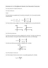
A<strong>digital</strong>filter is a basicbuilding block in any DigitalSignal Processing (DSP) system.The frequency responseof the filter depends on the value of itscoefficients, or taps. Many softwareprograms can compute the values of thecoefficients based on the desired frequencyresponse. These values are typicallyfloating point numbers <strong>and</strong> theyare represented with a fairly highdegree of precision.However, when a <strong>digital</strong> filter is implementedin hardware, the designer wantsto represent the coefficients (<strong>and</strong> alsothe data) with the smallest number ofbits that still gives acceptable resolutionfor the numbers. This is because representinga number with excess bitsincreases the size of the registers, buses,adders, multipliers <strong>and</strong> other hardwareused to process that signal. The biggersizes result in a chip with a larger diesize, which translates into increasedpower consumption <strong>and</strong> a higher chipprice. Thus, the bit precisions used torepresent numbers are important in theperformance of real-world signal processingdesigns.<strong>FIR</strong> <strong>digital</strong> <strong>filters</strong>A Finite Impulse Response (<strong>FIR</strong>)<strong>digital</strong> filter is one whose impulseresponse is of finite duration. This canbe stated mathematically ashn ( ) = { 0,n≤τ1 −∞< τ1 < τ2
k = N -1 where N is the number of feedbacktaps in the <strong>IIR</strong> filter. The right Σdenotes summation from k = 0 to k = M-1 where M is the number of feedforwardtaps.Note that, unlike the <strong>FIR</strong> filter, theoutput of an <strong>IIR</strong> filter depends on boththe previous M inputs <strong>and</strong> the previousN outputs. This feedback mechanism isinherent in any <strong>IIR</strong> structure. (Feedbackoccurs when a scaled version of the outputis fed back into the input.) It is|H(w)| (dB)Magnitude Of Floating Point <strong>FIR</strong> Filter0-20-40-60-80-1000 0.1 0.2 0.3 0.4 0.5Digital Frequency (Hz)Fig. 1 Results for floating point <strong>FIR</strong> <strong>and</strong> <strong>IIR</strong> <strong>filters</strong>|H(w)| (dB)|H(w)| (dB)|H(w)| (dB)Pole-Zero Plot Of Floating Point <strong>FIR</strong> Filter1.5Imaginary Axis10.50-0.5-1-1.5-1 0 1Real Axisresponsible for the infinite duration ofthe impulse response.How do we show that an <strong>IIR</strong> filtercan have an infinite duration impulseresponse? The easiest way is to considera simple two-tap <strong>IIR</strong> filter with the followingdifference equation( ) = ( − ) + ( )y n α y n 1 x n(4)Magnitude Response Of Floating Point <strong>IIR</strong> Filter0|H(w)| (dB)Magnitude Responses Of Bit Accurate <strong>FIR</strong> Filters0-50-1000 0.1 0.2 0.3 0.4 0.5Digital Frequency (Hz)0-50Float4 Bit-1000 0.1 0.2 0.3 0.4 0.5Digital Frequency (Hz)0-50Float10 BitFloat16 Bit-1000 0.1 0.2 0.3 0.4 0.5Digital Frequency (Hz)Fig. 2 Results for bit accurate <strong>FIR</strong> <strong>filters</strong>-50-100-150-2000 0.1 0.2 0.3 0.4 0.5Digital Frequency (Hz)Pole-Zero Plot Of Floating Point <strong>IIR</strong> Filter1.5Imaginary Axis10.50-0.5-1-1.5-1 0 1Real AxisPole-Zero Plots Of Bit Accurate <strong>FIR</strong> FiltersImaginary AxisImaginary AxisImaginary Axis10-110-110-1-1 0 1Real Axis-1 0 1Real Axis-1 0 1Real Axiswhere α is the value of the single feedbacktap a 1 in (3) <strong>and</strong> b 1 = 1 is the valueof the single feedforward tap. The inputto the filter is δ(n) <strong>and</strong> the output of thefilter at various times is shown in Table1. Note that although the input to the filterhad only one non-zero value (at timen = 0), the output of the filter is nonzerofor all time 0 ≤ n ≤∞. This is dueto the feedback nature of the <strong>IIR</strong> filter.From a mathematical st<strong>and</strong>point, thisimpulse response takes on non-zero valuesfor an infinite duration. However,the response of this <strong>IIR</strong> filter when realizedin practice will eventually die out.This happens when the numbersbecome too small to be represented withthe finite precision of the filter.Advantages of <strong>IIR</strong> <strong>filters</strong><strong>IIR</strong> <strong>filters</strong> are useful for high-speeddesigns because they typically require alower number of multiplies compared to<strong>FIR</strong> <strong>filters</strong>. <strong>IIR</strong> <strong>filters</strong> can also bedesigned to have a frequency responsethat is a discrete version of the frequencyresponse of an analog filter.Unfortunately, <strong>IIR</strong> <strong>filters</strong> do not havelinear phase <strong>and</strong> they can be unstable ifnot designed properly. <strong>IIR</strong> <strong>filters</strong> alsoare very sensitive to filter coefficientquantization errors that occur due tousing a finite number of bits to representthe filter coefficients. One way toreduce this sensitivity is to use a cascadeddesign. That is, the <strong>IIR</strong> filter isimplemented as a series of lower-order<strong>IIR</strong> <strong>filters</strong> as opposed to one high-ordersection. The effect of this implementationwill be shown later in this article.Poles <strong>and</strong> zerosA detailed discussion of what poles<strong>and</strong> zeros are is beyond the scope of thisarticle. The interested reader can findout more by looking in any DSP book.(See Read more about it for some possiblesources.) Only a very brief descriptionwill be given here.Suppose that a filter has the followingtransfer functionHz ( ) =( z−z1) ( z−z2) ( z−z3)( z−p1) ( z−p2) ( z−p3)(5)where z n <strong>and</strong> p n are values on the complexplane (z-domain). The zeros of thefunction are the values of z for whichH(z) equals zero. Hence, the zeros ofthis function are at z = {z 1 , z 2 , z 3 }.Similarly, the poles of the functionare those values of z for which H(z)equals infinity. Thus, the poles of thisfunction are at z = {p 1 , p 2 , <strong>and</strong> p 3 }.OCTOBER/NOVEMBER 2000 0278-6648/00/$10.00 © 2000 <strong>IEEE</strong> 29
When plotting the pole-zero plot of afunction, a circle (o) is used to denotethe location of a zero, <strong>and</strong> a cross (x) isused to denote a pole.ImplementationImplementing a <strong>digital</strong> filter in practicetypically involves using software todetermine the filter coefficients basedMagnitude Responses Of Bit Accurate <strong>IIR</strong> Filters0|H(w)| (dB)|H(w)| (dB)|H(w)| (dB)-50-100-150-2000 0.1 0.2 0.3 0.4 0.5Digital Frequency (Hz)0-50-100-150|H(w)| (dB)|H(w)| (dB)|H(w)| (dB)-50-100-1500Magnitude Responses Of BitAccurate Cascaded <strong>IIR</strong> FiltersFloat10 Bit-2000 0.1 0.2 0.3 0.4 0.5Digital Frequency (Hz)0-50-100-150Float15 Bit-2000 0.1 0.2 0.3 0.4 0.5Digital Frequency (Hz)0-50-100-150Float10 Bit-2000 0.1 0.2 0.3 0.4 0.5Digital Frequency (Hz)0-50-100-150Float15 BitFloat20 Bit-2000 0.1 0.2 0.3 0.4 0.5Digital Frequency (Hz)Fig. 3 Results for bit accurate <strong>IIR</strong> <strong>filters</strong>Float20 Bit-2000 0.1 0.2 0.3 0.4 0.5Digital Frequency (Hz)Fig. 4 Results for bit accurate cascaded <strong>IIR</strong> <strong>filters</strong>on various user-defined parameters. Thefilter design software usually computes<strong>and</strong> displays the filter coefficients witha high degree of precision. If the <strong>digital</strong>filter can be implemented using thatsame degree of precision, then the filterwill behave as predicted by the filterdesign software.In practice, only a finite number ofPole-Zero Plots Of Bit Accurate <strong>IIR</strong> FiltersImaginary AxisImaginary AxisImaginary Axis10-110-110-1Pole-Zero Plots Of BitAccurate Cascaded <strong>IIR</strong> FiltersImaginary AxisImaginary AxisImaginary Axis1 0 1Real Axis-1 0 1Real Axis-1 0 1Real Axis10-110-110-1-1 0 1Real Axis-1 0 1Real Axis-1 0 1Real Axisbits can be used to represent the <strong>digital</strong>filter coefficients. This reduction ineach coefficient’s precision causes thefrequency response of the filter to differfrom the “ideal” response due to coefficientquantization errors.When using B coeff bits to representthe filter coefficients, the total numberof possible values that the filter coefficientscan take on is 2 Bcoeff . Thus,instead of having an infinite range ofvalues for the coefficients, they areinstead constrained to one of the 2 Bcoefflevels. The location of the poles <strong>and</strong>zeros of the filter are also quantized.This is because they depend on thevalue of the filter coefficients.The quantization of the pole <strong>and</strong> zerolocations will typically move the poles<strong>and</strong> zeros of the filter to locations thatare different from the “ideal” setting.This can have drastic effects on the performanceof the filter.For example, suppose a pole is to belocated at a distance of 0.999 from theorigin. However, the quantization ofthat pole’s location can cause the poleto be moved to a location that is at a distanceof 1 from the origin (sinceQ{0.999} = 1 for certain bit precisionswhere Q{.} denotes quantization). Since<strong>filters</strong> with poles on the unit circle areunstable, quantization can cause stablefilter designs to become unstable whenactually implemented. Because of theeffects of filter coefficient quantization,the number of bits to assign to the filtercoefficients (<strong>and</strong> for the data as well)must be carefully chosen.Fixed point arithmeticFixed point arithmetic is a typical formatused to implement <strong>digital</strong> <strong>filters</strong> onboth DSP processors <strong>and</strong> in VLSI implementations.(Another popular format isfloating point arithmetic in which numbersare represented using two parts:mantissa <strong>and</strong> exponent.) A very popularform of fixed point arithmetic is thetwo’s complement fixed point format.In this format, a B-bit number’s mostsignificant bit (MSB) represents the signof the number. The lower B-1 bits representthe magnitude. Using this format, aB-bit number can represent signed numbersin the range from -2 B-1 to 2 B-1 -1.In two’s complement arithmetic, thenegative of a binary number is formed byinverting each bit of the number. We thenadd a 1 to the least significant bit (LSB).Table 2 shows all the numbers that can berepresented with 3 bits using the two’scomplement fixed point format.30 <strong>IEEE</strong> POTENTIALS
Simulation resultsTwo ninth-order lowpass <strong>filters</strong> weredesigned to demonstrate the effects ofusing finite bit precisions to represent<strong>digital</strong> filter coefficients. The first filteris a <strong>FIR</strong> filter, <strong>and</strong> the second one is an<strong>IIR</strong> filter. Both were designed by placingthe poles <strong>and</strong> zeros to get a filterwith a lowpass response.Figure 1 shows the frequencyresponse <strong>and</strong> the pole-zero plots forthese <strong>filters</strong>. These <strong>filters</strong> are referred toas the floating point <strong>filters</strong>: The coefficientsfor these <strong>filters</strong> are represented infloating point format with the full precisionof the computer. The frequencyresponses shown in Fig. 1 represent thedesired response. The other figures showhow using a reduced precision adverselyaffects the filter’s response. These <strong>filters</strong>are referred to as bit accurate.The coefficients for these <strong>filters</strong> arerepresented using the two’s complementfixed point format with a finite numberof bits. Three different bit precisions areused for each bit accurate filter to showthe performance for different precisions.Figure 2 shows the results for the bitaccurate <strong>FIR</strong> <strong>filters</strong>. The three plots onthe left show the frequency response forthe floating point filter in blue <strong>and</strong> forthe bit accurate <strong>filters</strong> in red. The bitprecisions for each bit accurate filter areshown on the plot’s legend.The three plots on the right show thepole-zero plots for the various <strong>FIR</strong> <strong>filters</strong>.Again, the blue corresponds to thelocations for the floating point filter <strong>and</strong>the red corresponds to the locations forthe bit accurate <strong>filters</strong>.At 16 bits, the bit accurate responsematches that of the floating point filter.When the precision drops to 10 bits, thelocation of the zeros changes. The frequencyresponse is altered slightly.Using only 4 bits for the filter coefficientshas a drastic effect on the locationof the zeros. (Some are moved intodifferent quadrants <strong>and</strong> even outside ofthe unit circle.) The frequency responseflattens out considerably.The results for the <strong>IIR</strong> <strong>filters</strong> areshown in Fig. 3. As the bottom plotshows, 20 bits gives a frequencyresponse that matches the floating pointfilter’s response. At 15 bits there is achange in the position of some of thepoles. The frequency response is shiftedupward. Using 10 bits leads to a slightchange in the position of a few zeros<strong>and</strong> significant changes in the positionsof the poles. The frequency response isTable 1 Output of example <strong>IIR</strong> filterfor an input of δ(n)Discrete time Filter input Filter outputinstance x(n) y(n)0 1 11 0 α2 0 α 23 0 α 3n 0 α nshifted upward even more.Note that the bit accurate <strong>FIR</strong> filter’sresponse matches the floating pointresponse when using 16 bits. Also, thereis only a slight degradation in the performancewhen using 10 bits. However,for the <strong>IIR</strong> filter, 20 bits matches thefloating point response, but droppingthe precision to 15 bits causes the frequencyresponse to change.These plots demonstrate that <strong>IIR</strong> <strong>filters</strong>are particularly susceptible to finitebit precision effects. This is due to thefeedback nature of the <strong>IIR</strong> structure. Itcauses the filter quantization effects tomagnify. One way to reduce this sensitivityis to implement the <strong>IIR</strong> filter as acascaded series of lower-order <strong>filters</strong>instead of one higher-order filter.For the plots shown in Fig. 3, the <strong>IIR</strong>filter was implemented as one ninthorderfilter. Figure 4 shows the resultsfrom implementing the same filter (samezero <strong>and</strong> pole locations) as a cascade offour second-order <strong>filters</strong> <strong>and</strong> one firstorderfilter. The bit accurate frequencyresponses match the response of thefloating point filter at precisions of 20<strong>and</strong> 15 bits (contrast this to the plots inFig. 3). Dropping the precision to 10 bitsshows a slight movement in the locationof some poles <strong>and</strong> zeros. But the effecton the frequency response is negligible.From these results, we see that thecascaded implementation requires alower bit precision when compared withthe precision needed for implementingthe <strong>IIR</strong> filter as a single ninth-order filter.The differences in the results shownin Figs. 3 <strong>and</strong> 4 highlight the effect thatimplementing a filter with differentstructures can have on its performance.ConclusionsThe simulation results presentedshow how finite bit precisions can affectthe performance of a <strong>digital</strong> filter. <strong>IIR</strong><strong>filters</strong> were shown to be even more susceptibleto finite bit precision effectsthan <strong>FIR</strong> <strong>filters</strong>. However, these effectsTable 2 Two’s complement fixedpoint format for 3 bit numbersDecimal format Fixed point format0 0001 0012 0103 011-4 100-3 101-2 110-1 111can be reduced using the <strong>IIR</strong> filter witha cascaded structure.AcknowledgmentsThe author would like to thank Dr.Tom “Fear & Loathing” Endres <strong>and</strong> Dr.Samir Hulyalkar (Sarnoff Digital Communications)for first getting the authorinterested in the wonderful world offinite bit precisions. Thanks also toTom Krauss (Purdue University) fornumerous discussions on finite bit precisions,cascaded <strong>filters</strong>, <strong>and</strong> the financialimplications of the Year 2000 bug.Read more about it• Ifeachor, E., <strong>and</strong> Jervis, B., DigitalSignal Processing: A PracticalApproach, Addison-Wesley, 1995.• Litwin, L., Endres, T., Hulyalkar,S., <strong>and</strong> Zoltowski, M., “The Effects OfFinite Bit Precision For A Fixed PointVLSI Implementation Of The ConstantModulus Algorithm,” InternationalConference on Acoustics, Speech, <strong>and</strong>Signal Processing, Phoenix, AZ, Vol. 4,pp. 2013-2016, March 1999.• Lyons, R., Underst<strong>and</strong>ing DigitalSignal Processing, Addison-Wesley, ’97.• Proakis, J., <strong>and</strong> Manolakis, D., DigitalSignal Processing: Principles, Algorithms,<strong>and</strong> Applications, Prentice-Hall, ’96.About the authorLouis Litwin is a Member of the TechnicalStaff in the Corporate Researchdepartment at Thomson Multimedia wherehe works on wireless <strong>digital</strong> home networkingtechnology. Mr. Litwin receivedhis M.S. degree in Electrical Engineeringfrom Purdue University in ’99 <strong>and</strong> his B.S.degree in Electrical Engineering with distinctionfrom Drexel University in ’97. Hewas named by Eta Kappa Nu as the AltonB. Zerby <strong>and</strong> Carl T. Koerner Outst<strong>and</strong>ingElectrical Engineering Student for ’97. Hisinterests include <strong>digital</strong> signal processing<strong>and</strong> <strong>digital</strong> VLSI design. He often annoysthe IRS by computing his income taxesusing only 3 bits of precision.OCTOBER/NOVEMBER 2000 31