CP505e-12 electronic Protractor user guide - Starrett
CP505e-12 electronic Protractor user guide - Starrett
CP505e-12 electronic Protractor user guide - Starrett

Create successful ePaper yourself
Turn your PDF publications into a flip-book with our unique Google optimized e-Paper software.
Y o u r a d v a n t a g e i s s t a r r e t t i n n o v a t i o n<br />
<strong>CP505e</strong>-<strong>12</strong> <strong>electronic</strong> <strong>Protractor</strong> <strong>user</strong> <strong>guide</strong><br />
Para ver el manual en español:<br />
www.starrett.com/u?505E-S<br />
Pour consulter la version française du manuel:<br />
www.starrett.com/u?505E-F<br />
<strong>CP505e</strong>-<strong>12</strong> Features<br />
1. Miter Cut (for miter joints)<br />
2. Single Cut (for butt joints)<br />
3. <strong>Protractor</strong> (0° to 180° to 360° to 180° to 0° - 180° to 0° to 180°)<br />
4. Compound Cut (for Crown Molding )<br />
Turn the knob clockwise to tighten the<br />
movement of the protractor arms.<br />
Fig. 1 Plumb Vial<br />
standard Miter (Default Setting)<br />
The Mode button is used to toggle the tool’s three main capabilities: Miter,<br />
<strong>Protractor</strong>, and Crown Molding.<br />
Miter is the default mode. The scale should read 90.0° with both arms on<br />
a flat surface. This mode is designed for use with a Miter/Chop saw with<br />
display indicating the saw setting.<br />
inside Miter Cut<br />
MITER<br />
MITER<br />
90.0<br />
Reset Button<br />
Measure<br />
Corner<br />
Mode<br />
Open the arms to place them against the two walls of the corner. Read the<br />
value from the display and press the HoLd button (Fig. 2). Set your saw to<br />
this angle (Fig. 3) and make your cut. Swing the saw to the opposite side,<br />
reset to the same value, and make your second cut (Fig. 4). For an outside<br />
corner, flip the face of the board down on to the table and repeat the steps<br />
above.<br />
Fig. 2<br />
Fig. 3<br />
Walls<br />
MITER<br />
90.0 46.2<br />
MITER<br />
Measure<br />
Corner<br />
The display shows the actual<br />
Miter angle to set your saw to.<br />
Left Board<br />
1<br />
Right Board<br />
st 2 Cut<br />
nd Cut<br />
Board Face<br />
46.2<br />
LCD Display<br />
Mode Button<br />
Next Button<br />
Select / Hold Button<br />
Fig. 4<br />
single Cut Miter<br />
A single cut miter is used to have a trim piece flush against a wall (Fig.<br />
6). Open the tool so the arms touch the walls. Press the neXt button<br />
and the single cut value will appear (Fig. 5). NOTE: This is usually a<br />
very slight angle.<br />
ADJUST SAW FOR SINGLE CUT<br />
2.4<br />
MITER<br />
Measure<br />
using the standard 360 degree <strong>Protractor</strong><br />
Press the Mode button until the display reads PROTRACTOR. Place the<br />
tool on a flat surface and collapse until the arms are aligned. Verify that<br />
the display reads 0.0°. If not, press the reset button. The display will then<br />
read 0.0°. Then, open the arms and you will see the display change from<br />
0° to 360° (Fig. 7).<br />
0.0<br />
PROTRACTOR<br />
0.0<br />
PROTRACTOR<br />
180.<br />
PROTRACTOR<br />
0<br />
Fig. 5<br />
Measure<br />
Fig. 7<br />
Pressing the neXt button displays the acute angle, changing the 0-360°<br />
standard protractor to one that reads 0-180-0° (Fig. 8).<br />
Measure<br />
Fig. 8<br />
Press the neXt button again and the display will show the obtuse angle,<br />
reading from 180-0-180° (Fig. 9).<br />
Walls<br />
Measure<br />
Floor Board<br />
2.4<br />
Saw Cut<br />
Fig. 6<br />
Fig. 9<br />
1
How to determine the Crown Molding spring angle<br />
The spring angle of crown molding stock is the angle from the back of the<br />
molding to the wall. While the spring angle is stamped on some stock, it is<br />
preferable to verify the measurement.<br />
Fig. 10<br />
Fig. 11<br />
Spring Angle<br />
39.4<br />
ADJUST SAW FOR MITER<br />
CROWN<br />
Ceiling<br />
Crown Molding<br />
Wall<br />
Fig. <strong>12</strong><br />
To make this measurement, place the molding on the edge of a work bench<br />
and set the material so the edge that will come into contact with the wall is<br />
facing down on to the surface of the bench.<br />
The molding will be on an angle. Lightly clamp the molding to hold in place<br />
(Fig. 11). Place the 505E under the bench top and open the arm so it mimics<br />
the angle of the molding. Place the 505E as shown in Fig. <strong>12</strong>, then press<br />
neXt and cycle through to the obtuse setting as shown in Fig. 13. This will be<br />
your spring angle. Common angles are 38°, 45°, or 52°.<br />
Fig. 13<br />
using a Custom angle<br />
To determine the miter angles using a custom spring angle, sequence<br />
through Mode to get to CroWn, then push the neXt button until CUS is<br />
displayed (Fig. 14).<br />
SPRING<br />
CUST<br />
CUS<br />
CROWN<br />
55.0<br />
CROWN<br />
SET SPRING<br />
CUST<br />
Fig. 14<br />
Press the seLeCt/HoLd button to set the spring angle. Move the arm of the<br />
protractor until the display shows the value of your custom angle (Fig. 15).<br />
Then Press the neXt button and measure the corner angle.<br />
If you find that your molding is not one of the standard spring angles using<br />
the steps above, use the custom option to determine the angles for your cut.<br />
First, write down your custom angle (Fig. 15).<br />
MEASURE<br />
CORNER<br />
SPRING<br />
CUST<br />
Press neXt to attain the miter angle (Fig. 16). Then press neXt and set your<br />
blade to the bevel angle displayed (Fig. 17).<br />
Fig. 16<br />
PROTRACTOR<br />
38.0<br />
23.9<br />
ADJUST SAW FOR BEVEL<br />
CROWN<br />
Measure<br />
Fig. 15<br />
SPRING<br />
CUST<br />
Fig. 17<br />
Bevel and Miter angles for Crown Molding Cuts<br />
Press the Mode button until CroWn is displayed. Press the neXt button to<br />
select the spring angle that coincides with your molding. Choices are 38°,<br />
45°, 52°, or Custom.<br />
Use the seLeCt/HoLd button to lock in this value. Open the tool and place it<br />
in the corner to be measured. Note the value in degrees (Fig. 18).<br />
89.0<br />
Press the neXt button to display the miter saw blade setting (Fig. 19).<br />
32.1<br />
ADJUST SAW FOR MITER<br />
34.2<br />
ADJUST SAW FOR BEVEL<br />
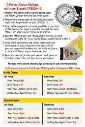
Making the Cut, Crown Molding<br />
Use the chart below for settings and layout for crown molding cuts with a<br />
compound miter saw.<br />
inside Corner<br />
Left Piece right Piece<br />
Work Piece Location: Left to Blade Work Piece Location: Left of Blade<br />
Miter Swing: Right Miter Swing: Left<br />
Bevel Swing: Left Bevel Swing: Left<br />
Molding Edge Against Fence: Top Molding Edge Against Fence: Bottom<br />
outside Corner<br />
Left Piece right Piece<br />
Work Piece Location: Right of Blade Work Piece Location: Right of Blade<br />
Miter Swing: Left Miter Swing: Right<br />
Bevel Swing: Right Bevel Swing: Right<br />
Molding Edge Against Fence: Bottom Molding Edge Against Fence: Top<br />
Form 970 1M/Q<br />
01/<strong>12</strong> specifications subject to change.<br />
978-249-3551 starrett.com 2<br />
CROWN<br />
CROWN<br />
CROWN<br />
38<br />
38<br />
MEASURE<br />
CORNER<br />
SPRING<br />
SPRING<br />
Press NEXT again to display the bevel angle setting (Fig. 20).<br />
SPRING<br />
Fig. 18<br />
Fig. 19<br />
Fig. 20