Distillation Column Internals/Configurations for Process ... - pierre
Distillation Column Internals/Configurations for Process ... - pierre
Distillation Column Internals/Configurations for Process ... - pierre

Create successful ePaper yourself
Turn your PDF publications into a flip-book with our unique Google optimized e-Paper software.
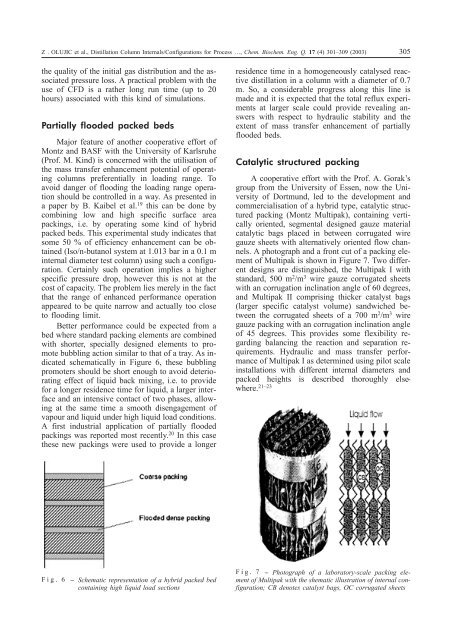
Z . OLUJIC et al., <strong>Distillation</strong> <strong>Column</strong> <strong>Internals</strong>/<strong>Configurations</strong> <strong>for</strong> <strong>Process</strong> …, Chem. Biochem. Eng. Q. 17 (4) 301–309 (2003) 305the quality of the initial gas distribution and the associatedpressure loss. A practical problem with theuse of CFD is a rather long run time (up to 20hours) associated with this kind of simulations.Partially flooded packed bedsMajor feature of another cooperative ef<strong>for</strong>t ofMontz and BASF with the University of Karlsruhe(Prof. M. Kind) is concerned with the utilisation ofthe mass transfer enhancement potential of operatingcolumns preferentially in loading range. Toavoid danger of flooding the loading range operationshould be controlled in a way. As presented ina paper by B. Kaibel et al. 19 this can be done bycombining low and high specific surface areapackings, i.e. by operating some kind of hybridpacked beds. This experimental study indicates thatsome 50 % of efficiency enhancement can be obtained(Iso/n-butanol system at 1.013 bar in a 0.1 minternal diameter test column) using such a configuration.Certainly such operation implies a higherspecific pressure drop, however this is not at thecost of capacity. The problem lies merely in the factthat the range of enhanced per<strong>for</strong>mance operationappeared to be quite narrow and actually too closeto flooding limit.Better per<strong>for</strong>mance could be expected from abed where standard packing elements are combinedwith shorter, specially designed elements to promotebubbling action similar to that of a tray. As indicatedschematically in Figure 6, these bubblingpromoters should be short enough to avoid deterioratingeffect of liquid back mixing, i.e. to provide<strong>for</strong> a longer residence time <strong>for</strong> liquid, a larger interfaceand an intensive contact of two phases, allowingat the same time a smooth disengagement ofvapour and liquid under high liquid load conditions.A first industrial application of partially floodedpackings was reported most recently. 20 In this casethese new packings were used to provide a longerresidence time in a homogeneously catalysed reactivedistillation in a column with a diameter of 0.7m. So, a considerable progress along this line ismade and it is expected that the total reflux experimentsat larger scale could provide revealing answerswith respect to hydraulic stability and theextent of mass transfer enhancement of partiallyflooded beds.Catalytic structured packingA cooperative ef<strong>for</strong>t with the Prof. A. Gorak’sgroup from the University of Essen, now the Universityof Dortmund, led to the development andcommercialisation of a hybrid type, catalytic structuredpacking (Montz Multipak), containing verticallyoriented, segmental designed gauze materialcatalytic bags placed in between corrugated wiregauze sheets with alternatively oriented flow channels.A photograph and a front cut of a packing elementof Multipak is shown in Figure 7. Two differentdesigns are distinguished, the Multipak I withstandard, 500 m 2 /m 3 wire gauze corrugated sheetswith an corrugation inclination angle of 60 degrees,and Multipak II comprising thicker catalyst bags(larger specific catalyst volume) sandwiched betweenthe corrugated sheets of a 700 m 2 /m 3 wiregauze packing with an corrugation inclination angleof 45 degrees. This provides some flexibility regardingbalancing the reaction and separation requirements.Hydraulic and mass transfer per<strong>for</strong>manceof Multipak I as determined using pilot scaleinstallations with different internal diameters andpacked heights is described thoroughly elsewhere.21–23Fig. 6 Schematic representation of a hybrid packed bedcontaining high liquid load sectionsFig. 7 Photograph of a laboratory-scale packing elementof Multipak with the shematic illustration of internal configuration;CB denotes catalyst bags, OC corrugated sheets