Distillation Column Internals/Configurations for Process ... - pierre
Distillation Column Internals/Configurations for Process ... - pierre
Distillation Column Internals/Configurations for Process ... - pierre

You also want an ePaper? Increase the reach of your titles
YUMPU automatically turns print PDFs into web optimized ePapers that Google loves.
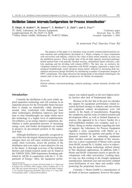
Z . OLUJIC et al., <strong>Distillation</strong> <strong>Column</strong> <strong>Internals</strong>/<strong>Configurations</strong> <strong>for</strong> <strong>Process</strong> …, Chem. Biochem. Eng. Q. 17 (4) 301–309 (2003) 301<strong>Distillation</strong> <strong>Column</strong> <strong>Internals</strong>/<strong>Configurations</strong> <strong>for</strong> <strong>Process</strong> Intensification*@. Olujiæ, B. Kaibel**, H. Jansen**, T. Riet<strong>for</strong>t**, E. Zich**, and G. Frey**TU Delft, Laboratory <strong>for</strong> <strong>Process</strong> Equipment,Leeghwaterstraat 44, NL-2628 CA Delft**Julius Montz GmbH, Hofstrasse 82, D-40723 HildenConference paperReceived: Juny 14, 2003Accepted: September 1, 2003In memoriam Prof. Emeritus Franc ŠefThe purpose of this paper is to introduce some recently commercialised packed columninternals and configurations developed at J. Montz company in close cooperationwith universities and industry, which by the virtue of their nature intensify in some waythe distillation process. These include state of the art high capacity structured packings,hybrid packed beds with partially flooded sections, streamlined liquid collectors, catalyticpackings and the dividing wall column (DWC). The later one, an exclusive developmentrealised in a close cooperation with BASF company, represents a major technologicalbreakthrough; recent advances being mainly reflected in increasing both mechanicaland process design flexibility by introducing a number of proprietary designs ofDWC components. This paper discusses the backgrounds of developed technologies, therelated state of the art and the perspectives <strong>for</strong> further development.Keywords:Packed columns, structured packings, catalytic packings, column internals, divided wallcolumnIntroduction*Based on the contents of a lecture delivered jointly by Z. Olujic andB. Kaibel at the ACHEMA 2003 Congress, held in Frankfurt aM, 19–24May 2003 and a lecture delivered by Z. Olujic at the 6th Italian Conferenceon Chemical Engineering (ICheaP6), held in Pisa, 8–11 June 2003.Corresponding author: z.olujic@wbmt.tudelft.nlCertainly the distillation is the most widely appliedseparation technology and will continue as animportant process <strong>for</strong> the <strong>for</strong>eseeable future becausethere is simply no industrially viable alternativearound. Also, confronted with challenges fromother technologies distillation improves and fromtime to time breakthroughs are made which movethis technology to a higher level of sophistication.Nevertheless, as an energy intensive separation, distillationis under permanent pressure of increasingenergy costs, and further developments are neededto preserve its pre-eminent position in the separationfield.Although distillation is generally recognized asone of the best developed chemical processing technologiesthere are still many technical barriers thatcould, when overcome, secure the position of thedistillation and even make it more attractive <strong>for</strong> usein the future. A thorough overview of the technicalbarriers and related research needs can be found inthe VISION 2020, 2000 Separations Roadmap publishedby AIChE in cooperation with the U. S. Departmentof Energy. 1 Here, the equipment per<strong>for</strong>mancewas ranked equally as the next highest prioritybarriers after lack of fundamental data.Because of the fact that in the past two decadesthe support <strong>for</strong> equipment per<strong>for</strong>mance related researchdeclined strongly in industry and universitiesthe equipment related developments were leftmainly in the hands of manufacturers. Regardingthe complexity and the scale of related research anddevelopment ef<strong>for</strong>t, as well as limited financial resources,this appeared to be a heavy burden <strong>for</strong> awell-established medium size company such as J.Montz. Being in similar situation regarding the lackof support, the Laboratory <strong>for</strong> <strong>Process</strong> Equipmentregarded a close cooperation with Montz as achance to maintain the quantity and quality of fundamentalresearch in the contacting equipmentfield. Another essential ingredient of this associationwas a close cooperation of Montz with a groupfrom BASF, around Dr. G. Kaibel, active in improvingthe packed column technology utilised mainlyin fine chemicals applications. In addition, both J.Montz and BASF cooperated closely at specific developmentswith other universities. Looking back,we may say that working in the triangle equipmentmanufacturer, industrial user and university enabledcross-fertilization of new ideas and models whileprotecting the proprietary know-how.Certainly, J. Montz GmbH is a manufacturer ofall kinds of process equipment, however this paper
Z . OLUJIC et al., <strong>Distillation</strong> <strong>Column</strong> <strong>Internals</strong>/<strong>Configurations</strong> <strong>for</strong> <strong>Process</strong> …, Chem. Biochem. Eng. Q. 17 (4) 301–309 (2003) 305the quality of the initial gas distribution and the associatedpressure loss. A practical problem with theuse of CFD is a rather long run time (up to 20hours) associated with this kind of simulations.Partially flooded packed bedsMajor feature of another cooperative ef<strong>for</strong>t ofMontz and BASF with the University of Karlsruhe(Prof. M. Kind) is concerned with the utilisation ofthe mass transfer enhancement potential of operatingcolumns preferentially in loading range. Toavoid danger of flooding the loading range operationshould be controlled in a way. As presented ina paper by B. Kaibel et al. 19 this can be done bycombining low and high specific surface areapackings, i.e. by operating some kind of hybridpacked beds. This experimental study indicates thatsome 50 % of efficiency enhancement can be obtained(Iso/n-butanol system at 1.013 bar in a 0.1 minternal diameter test column) using such a configuration.Certainly such operation implies a higherspecific pressure drop, however this is not at thecost of capacity. The problem lies merely in the factthat the range of enhanced per<strong>for</strong>mance operationappeared to be quite narrow and actually too closeto flooding limit.Better per<strong>for</strong>mance could be expected from abed where standard packing elements are combinedwith shorter, specially designed elements to promotebubbling action similar to that of a tray. As indicatedschematically in Figure 6, these bubblingpromoters should be short enough to avoid deterioratingeffect of liquid back mixing, i.e. to provide<strong>for</strong> a longer residence time <strong>for</strong> liquid, a larger interfaceand an intensive contact of two phases, allowingat the same time a smooth disengagement ofvapour and liquid under high liquid load conditions.A first industrial application of partially floodedpackings was reported most recently. 20 In this casethese new packings were used to provide a longerresidence time in a homogeneously catalysed reactivedistillation in a column with a diameter of 0.7m. So, a considerable progress along this line ismade and it is expected that the total reflux experimentsat larger scale could provide revealing answerswith respect to hydraulic stability and theextent of mass transfer enhancement of partiallyflooded beds.Catalytic structured packingA cooperative ef<strong>for</strong>t with the Prof. A. Gorak’sgroup from the University of Essen, now the Universityof Dortmund, led to the development andcommercialisation of a hybrid type, catalytic structuredpacking (Montz Multipak), containing verticallyoriented, segmental designed gauze materialcatalytic bags placed in between corrugated wiregauze sheets with alternatively oriented flow channels.A photograph and a front cut of a packing elementof Multipak is shown in Figure 7. Two differentdesigns are distinguished, the Multipak I withstandard, 500 m 2 /m 3 wire gauze corrugated sheetswith an corrugation inclination angle of 60 degrees,and Multipak II comprising thicker catalyst bags(larger specific catalyst volume) sandwiched betweenthe corrugated sheets of a 700 m 2 /m 3 wiregauze packing with an corrugation inclination angleof 45 degrees. This provides some flexibility regardingbalancing the reaction and separation requirements.Hydraulic and mass transfer per<strong>for</strong>manceof Multipak I as determined using pilot scaleinstallations with different internal diameters andpacked heights is described thoroughly elsewhere.21–23Fig. 6 Schematic representation of a hybrid packed bedcontaining high liquid load sectionsFig. 7 Photograph of a laboratory-scale packing elementof Multipak with the shematic illustration of internal configuration;CB denotes catalyst bags, OC corrugated sheets
306 Z . OLUJIC et al., <strong>Distillation</strong> <strong>Column</strong> <strong>Internals</strong>/<strong>Configurations</strong> <strong>for</strong> <strong>Process</strong> …, Chem. Biochem. Eng. Q. 17 (4) 301–309 (2003)The trouble with reactive distillation is that dueto excessive costs the experimentation with realsystems is limited to too small columns, i.e. there isno intermediate/semi-industrial scale ef<strong>for</strong>t availableto develop systematically the necessary scale--up knowledge. This is expected to be developed bycombining model developments and non-reactive,i.e. hydraulics and separation efficiency relatedtests at larger scale to validate accordingly predictivemodels, taking into account reaction kineticsin<strong>for</strong>mation obtained from small-scale experiments.This approach is outlined to some extent in ref. 23.A state of the art review of the reactive distillationtechnology based on BASF experiences is given inthe paper by Althaus and Schoenmakers. 24 A specialissue of Chemical Engineering and <strong>Process</strong>ing(March 2003) is devoted to reactive separations.Finally, it should be noted that in the meantimeJ. Montz GmbH decided to drop this line of developmentand transferred its rights <strong>for</strong> Multipak toSulzer Chemtech. Based on a much wider involvementwith all aspects of this technology, SulzerChemtech expects a breakthrough to happen in thisfield upon consolidation of the implementation relatedknowledge. 25Dividing wall columnFirst concepts of dividing wall (partitioned) columnscan be traced back in 1930s and 1940s. 26,27 Inthe same period, Brugma 28 laid the fundaments <strong>for</strong>what is known today generally as thermally coupleddistillation. However the credit <strong>for</strong> full recognition ofthe energy conservation potential of fully thermallycoupled distillation columns goes to Felix Petlyuk,who published with co-workers in the mid 1960s apaper 29 that represents the milestone in the developmentof this technology. A dividing wall column(DWC) is the most daring variation of the so-calledPetlyuk column. Its major feature is that it allowssubstantial energy savings, while separating in a singlebody a three-component mixture into pure products.A conventional configuration <strong>for</strong> separation ofa three-component mixture into pure components isshown in Fig. 8 together with a Petlyuk- and a DWCconfiguration. Obviously, the dividing wall columnrepresents the most compact configuration, which allowsboth considerable energy and capital saving.However, in spite of potential benefits, <strong>for</strong> yearsDWC remained to be an exotic academic conceptand even the energy price explosion of mid 1970swas not good enough to push toward its industrialimplementation. Certainly, it may look strange thatthe application pioneer, the company BASF, realisedsome twenty columns be<strong>for</strong>e other companies consideredthis as a possibility.Fig. 8 <strong>Distillation</strong> configurations <strong>for</strong> separation of a threecomponent mixture: (a) conventional, (b) thermallycoupled – Petlyuk, and (c) dividing wall columnReintroduced to the distillation community byG. Kaibel in 1987, 30 the dividing wall column is consideredtoday to be an established technology with asteadily growing application potential, including alsoseparation of four component mixtures. Energy savingswith respect to conventional two-column arrangementsare in the range of 30 %. A realistic ideaon this and other practical benefits from the utilisationof DWCs can be obtained from a paper byEnnenbach et al. 31 The most recent paper by Kolbeand Wenzel 32 discusses the potential <strong>for</strong> applicationin processing petrochemical cuts. Certainly academicpeople also embarked on this idea, and over the lastten years a good deal of academic and industrial researchef<strong>for</strong>t went into the evaluation of the energysaving potential in various applications. 33–35However it should be noted that the implementationof this concept required specific constructionalsolutions. An idea on the internal configuration of apacked DWC can be obtained from Figure 9. SpecialDWC related know-how was developed from the beginningat J. Montz GmbH, which built the BASFcolumns. For instance, the first columns were providedwith a fixed dividing wall, which was weldedon both sides to the column shell. To provide <strong>for</strong>better flexibility of the internal configuration and toreduce the design accuracy requirements of the system,a free, movable wall system was employed innew designs. For larger diameter columns the dividingwall is built by assembling it in the column fromspecially designed, easy to install manhole size segments(see Fig. 10). Such details including the edgeseals and other constructive solutions belong to theproprietary know-how of Montz. Modern concepts