A Formal Semantics of UML Sequence Diagram - UNU-IIST - United ...
A Formal Semantics of UML Sequence Diagram - UNU-IIST - United ...
A Formal Semantics of UML Sequence Diagram - UNU-IIST - United ...
You also want an ePaper? Increase the reach of your titles
YUMPU automatically turns print PDFs into web optimized ePapers that Google loves.
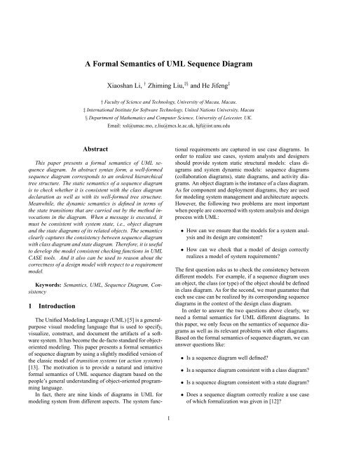
and edges represent links and passing messages. Since asequence diagram is defined as a sequence <strong>of</strong> messages, weshould give formal definition <strong>of</strong> messages.Definition 1 A message is a tuple:wheremsg = (ob i : C i , ob j : C j , action, order)• ob i is the source object <strong>of</strong> the message with class typeC i , <strong>of</strong> course the source <strong>of</strong> message can also be anactor.• ob j is the target object <strong>of</strong> the message with class typeC j .• action is a guarded method call <strong>of</strong> the form g → act ,where g is a Boolean expression <strong>of</strong> attributes <strong>of</strong> sourceobject ob i , and possibly public variables, and actionis either a command without method calls (an internalaction) or a method call ob j .m().• order is the order number <strong>of</strong> the message in the correspondingsequence diagram structure tree. All the ordernumbers <strong>of</strong> messages in the sequence diagram constructa partial order. The order number <strong>of</strong> a messageis given according to its position in the tree. The rootnode is corresponding to the starting object or actor <strong>of</strong>a sequence diagram. Then the first layer branches withorder number is 1, 2, , 3, · · · , n. From the u-th nodeob u <strong>of</strong> first layer object nodes, perhaps there are mnodes. The corresponding order numbers <strong>of</strong> branchesare u.1, u.2, · · · , u.m. The u.v is the v-th branchesfrom the node object ob u . Given the sequence diagramexample in Figure 2, the corresponding structure treewith ordered messages is shown in Figure 7.We now look at how composite diagrams can be constructedfrom basic diagrams by using programming language-likeconstructs.obi : Cig -> m()obj : Cjg -> m()Figure 3. Basic activation notationobi : Ciobj : Cj• The activation notation <strong>of</strong> a basic message in sequencediagram is shown in Figure 3.• The iterative notation <strong>of</strong> messages is shown in Figure4. The corresponding ordered tree can be constructedin the figure.• The special messages such as create object anddestroy are shown in Figure 5.• And the branching choice case <strong>of</strong> messages can bedealt as shown in Figure 6.obi : Cig -> m()u.v.1: * g1 -> n1()u.v : g -> m()obk : Ckobj : Cjobi : Ci* g1 -> n1()g2 -> n2()obj : Cjobk : Ckobk : Cku.v.2: g2 -> n2()Figure 4. Iteration notationA complicate sequence diagram can be constructed byabove basic notations. For sequence diagram <strong>of</strong> Figure 2,we can easily derive its corresponding message orderedstructure tree as shown in Figure 7.The ordered structure tree presents the hierarchical relationshipsamong the messages. And the execution <strong>of</strong> messages(i.e. execution <strong>of</strong> the method represented by the message)in the sequence diagram must follow the traversingrule <strong>of</strong> first root then son trees from left to right. For onethread sequence diagram, there is only one token to denotecontrol right <strong>of</strong> invoking message. In the beginning <strong>of</strong> anexecution <strong>of</strong> the sequence diagram, the token is in the actor’shand. When the source <strong>of</strong> message wants to invokea message, the source object or actor must hold the token.When the message is invoked, the token should be passedthe target <strong>of</strong> message. The source <strong>of</strong> message will wait untilthe target return the token, it can invoke another messageor return the token to the previous source which invoked itbefore. We consider that the execution <strong>of</strong> a sequence diagramfrom the start to termination is the process <strong>of</strong> the token4
obi : Ciobi : Ciobj : Cjobj=new Cj()obj : Cjb1 -> m()destroy()b2 -> n()obi : Ciobi : Ciu.v: obj=new Cj()u.v+1: destroy()u.v: b1 -> m()u.v+1: b2 -> n()obj : Cjobj : CjFigure 5. Create and destroy notationsobj : Cjobj : Cjtraversing from the root node <strong>of</strong> the hierarchical tree to subtreesfrom left to right, finally the token return back to theroot.If the order <strong>of</strong> the messages given in one thread sequencediagram is not conformed to a hierarchical structure tree,then the diagram is not well-formed. For example, the sequencediagram shown in Figure 8 is illegal because afterthe first message getName() finished, the thread controlpoint is returned the actor CampaignManager, the nextmessage ∗getCost() can be invoked by object : Campaignin the system.Figure 6. Branching choice notationCampaign Manager1: getName() 2: listCampaigns() 3: checkCapaingnBudget():Client2.1: *getCampaignDetails():Client:Campaign3.1: *getCost() 3.2: getOverheads()4 Computational Model:Campaign:Advert:CampaignWe use a notation similar to a transition or action system[13] to combine the models <strong>of</strong> class diagrams and themodel <strong>of</strong> sequence diagrams together to model a design <strong>of</strong>a system. A system is defined by a tuple (α, Φ, Θ, P ) where• α denotes the set <strong>of</strong> program variables known to theprogram.• P is a set <strong>of</strong> operations, each <strong>of</strong> which is a predicatethat relates the initial values <strong>of</strong> program variables. Thepredicate is <strong>of</strong> the form p(x) ⊢ R(x, x ′ ) (called a designin [9]):p(x) ⊢ R(x, x ′ ) def= ok ∧ p(x) ⇒ ok ′ ∧ R(x, x ′ )where x and x ′ represent the initial and final values<strong>of</strong> x respectively; ok asserting that the operation isstarted well and ok ′ means that the operation terminated;p(x) is called the precondition, and R(x, x ′ ) thepost-condition or the transition relation.Figure 7. <strong>Sequence</strong> diagram structure tree• Θ is a predicate over α, called the initial condition anddefines the initial state(s) <strong>of</strong> the system.• Φ is a predicate over α, called the invariant. It must betrue in any initial state and preserved by each operationin P .An action only changes a subset <strong>of</strong> variables declared inα. The normal form <strong>of</strong> a design is thus a framed design <strong>of</strong>the form V : (p ⊢ R), that denotes p ⊢ R ∧ (w ′ = w),where V and w are subsets <strong>of</strong> α, and w = α − V . Whenthere is no confusion, we will omit the frame in a design byassuming that a variable x can be changed by a design onlyif its primed version x ′ occurs in the design.The above model has to take into account the followingOO aspects.1. A sequence diagram is composed from a number <strong>of</strong>5
¡CampaignManagergetName()¡¡¡¡¡¡¡¡¡¡¡¡¡¡¡¡¡¡¡¡¡¡¡¡¡¡¡¡¡¡¡¡¡¡¡¡listCampaigns():ClientcheckCampaignBudget()* getCampaignDetails():Campaign* getCost()* getCost():AdvertgetOverheads()Figure 8. Illegal sequence diagramoperations, i.e. method calls, while a class diagramsdetermines the following variables on which sequencediagram operates:• for every class, a class variable that takes values<strong>of</strong> sets <strong>of</strong> objects <strong>of</strong> the concept;• for every object <strong>of</strong> a concept, a variable for eachattribute <strong>of</strong> the concept;• for every association, an association variablethat take values <strong>of</strong> sets <strong>of</strong> links (i.e. pairs) betweenobjects <strong>of</strong> the associated classes.2. Due to the inheritance mechanism, the effect <strong>of</strong> a usecase on a variable depends on its current type duringexecution, rather than its originally declared type.3. As in imperative languages, a state <strong>of</strong> a variable is itscurrent value. An object is represented as a finite tuplethat records its identity, current type, and the values <strong>of</strong>its attributes.In summary, a model <strong>of</strong> an OO design is a system S =(α, Φ, Θ, P ) where• P consists <strong>of</strong> a set <strong>of</strong> operations obtained from a number<strong>of</strong> sequence diagrams.• α identifies the variables on which the operations in Poperate and it is determined by the class diagram andthe input and output parameters <strong>of</strong> the methods in thesequence diagram.• The invariant Φ formally models the invariant constraint,such as multiplicities and business rules. Thepair (α, Φ) thus gives the formalization <strong>of</strong> the classmodel.• Θ is a condition to be established when starting up thesystem.5 <strong>Formal</strong> <strong>Semantics</strong> <strong>of</strong> <strong>Sequence</strong> <strong>Diagram</strong>We consider both static and dynamic semantics <strong>of</strong> sequencediagrams. In an abstract syntactic form, a wellformedsequence diagram corresponds to an ordered hierarchicaltree structure. The static semantics <strong>of</strong> a sequencediagram is to check whether it is consistent with the classdiagram declaration. This means that the static semantics isalways dependent on a given class diagram ∆. Meanwhile,the dynamic semantics is defined as a sequence composition<strong>of</strong> the first layer system messages <strong>of</strong> its ordered tree.When a message is executed, it must be consistent with systemstate, i.e., object diagram and the state diagrams <strong>of</strong> therelevant objects.5.1 Static semantics <strong>of</strong> sequence diagramGiven a class diagram ∆, let CN be the set <strong>of</strong> classnames in ∆, AN set <strong>of</strong> association names, Ass the set <strong>of</strong>all associations each <strong>of</strong> which is represented in the form< C 1 , A, C 2 >, where C 1 , C 2 ∈ CN and A ∈ CN, andmethod(C) be the set <strong>of</strong> all the methods <strong>of</strong> class C in ∆.Obviously, for a given messagemsg = (ob i : C i , ob j : C j , g → m(), order)we can define its static semantics as follows.S s [smg]] def= C i ∈ CN ∧ C j ∈ CN∧∃A ∈ CN. < C i , A, C j >∈ Ass ∧ m ∈ Method(C j )The static semantics <strong>of</strong> a sequence diagram is defined asthe conjunction <strong>of</strong> all its messages in the structure tree.5.2 Dynamic <strong>Semantics</strong> <strong>of</strong> MessageExecution <strong>of</strong> a message makes system change from onestate s to another s ′ . Based on Hoare and He’s UnifyingTheories <strong>of</strong> Programming [9], we can define a message actionas first order logic formula on a pair <strong>of</strong> system states(s, s ′ ). Before giving the semantics <strong>of</strong> messages, we introducesome useful auxiliary functions: for states s and s ′ ,• s(C) : the set <strong>of</strong> objects <strong>of</strong> class C in state s.• s(ob): the corresponding state <strong>of</strong> object ob in systemstate s, i.e. the values <strong>of</strong> the attributes <strong>of</strong> ob.6
• s(g): a boolean value <strong>of</strong> guard condition g under systemstate s.• Enable(s, ob, m) : a boolean value. It equals tureif the method m <strong>of</strong> object ob is enabled under systemstate s.• pre s (ob.m): the precondition <strong>of</strong> method m <strong>of</strong> objectob under system state s.• post (s,s ′ )(ob.m): the postcondition <strong>of</strong> method m <strong>of</strong>object ob under system state pair (s, s ′ ).• Link(s, ob) : the object set which can be navigatedfrom object ob by its associations in the system state s.we can define the dynamic semantics <strong>of</strong> action execution(except create action) as follows:• A method invocation can only be executed when themethod is enabled in the current state:S d [[ob.m()]] def=Enable(s, ob, m)∧(pre s (ob.m) ⇒ post (s,s ′ )(ob.m))• A guarded message invocation can go ahead only whenthe guard is evaluated to be in the current state:S d [[g → ob.m()]] def= s(g) ∧ S d [[ob.m()]]• Branching provides a choice according to guards ornon-deterministically if both guards are true:S d [[b1 → ob 1 .m() ⊓ b2 → ob 2 .n()]] def=(s(b1) ∧ S d [[ob 1 .m()]]) ∨ (s(b2) ∧ S d [[ob 2 .n()]])• An iteration repeats the execution until the guard becomesfalse:S d [[∗ b → ob.m()]] def= (b ∗ S d [[ob.m()]])• To destroy an object is to remove the object from thesystem state:S d [[ob i .destroy()] def= s ′ (C i ) = s(C i ) − {ob i }where C i is the type class <strong>of</strong> ob i .When a message is executed, some consistent conditionsshould be checked under system state. The dynamic semantics<strong>of</strong> a message: (ob j : C i , ob j : C j , act), can be definedon a pair system (s, s ′ ) as follows, where act is not createobject action.LetwhereP oss def=ob i ∈ s(C i ) ∧ ob j ∈ s(C j ) ∧ ob j ∈ Link(s, ob i )S d [[(ob i : C i , ob j : C j , act)]] def=S d [[act] ✁ P oss ✄ falseP ✁ b ✄ Q def= b ∧ P ∨ ¬b ∧ QAn object can create a new object only when it is already inthe state, the new object must not exist in the current state.The semantics <strong>of</strong> the action create as ob j = new C j () isdefined as follows:∃o ∉ s(C j ).(ob j = o) ∧ s ′ (C j ) = s(c j ) ∪ {ob}∧Link(s ′ , ob i ) = Link(s, ob i ) ∪ {ob j }✁ob i ∈ s(C i )✄false5.3 Dynamic semantics <strong>of</strong> sequence diagramThe dynamic semantics <strong>of</strong> a sequence diagram can bedefined as the sequence composition <strong>of</strong> the first layermessages in its corresponding ordered structure tree discussedin Section 3. For example, the message sequence< msg 1 , msg 2 , · · · , msg n > is the first layer messagesfrom left to right <strong>of</strong> a sequence diagram SD. The semantics<strong>of</strong> SD can be defined as follows.S d [[SD]] def=c 1 ; S d [[msg 1 ]]; c 2 ; S d [[msg 2 ]]; · · · ; S d [[msg n ]]; c n+1where c 1 , c 2 , · · · , c n and c n+1 are small pieces <strong>of</strong> programor skip defined in the method, which are defined in s<strong>of</strong>twareimplementation phase. If a group <strong>of</strong> neighbor messages arein choice or iterative relations rather than in sequence relation,we can handle the semantics similarly as the dynamicsemantics definition <strong>of</strong> above message.For a composite message msg i with a sequence message< msg i.1 , msg i.2 , · · · , msg i.m > at the layer below, its semanticscan be roughly defined as follows because someexecution information <strong>of</strong> the method is not provided in thesequence diagram.S d [[msg i ]] def=c 1 ; S d [[msg i.1 ]]; · · · ; c m ; S d [msg i.m ]]; c m+1However, a sequence diagram is generally invoked by anactor <strong>of</strong> the system [10]. In this case, the semantics can7
e simply defined as follows since there are not pieces programsbetween two system method calls.S d [[SD]] def= S d [[msg 1 ]]; S d [[msg 2 ]; · · · ; S d [[msg n ]]For example, the dynamic semantics <strong>of</strong> the sequence diagramin Figure 1 can be defined as follows.S d [[SD]] def= S d [[: Client.getName()] ;S d [[: Client.listCampaign()]] ;S d [[: Campaign.checkCampaignBudget()]]where the two messages : Client.listCampaing and :Campaign.checkCampaignBudget() must be executedas the following defined execution traces.S d [[: Client.listCampaign()]] = c 1 ;true ∗ S d [: Compaign.getCampaignDetails()]]; c 2S d [[: Campaign.checkCampaignBudget()]] =c 3 ; true ∗ S d [[: Advert.getCost()]]; c 4 ;S d [[: Campaign.getOverheads()]]; c 56 Conclusion and Future Work6.1 ConclusionThe most informal parts <strong>of</strong> <strong>UML</strong> are the descriptions <strong>of</strong>use cases and the links between different <strong>UML</strong> diagrams.Reports on teaching and using <strong>UML</strong> for s<strong>of</strong>tware developmentshow that the majority <strong>of</strong> inconsistencies are causedby the lack <strong>of</strong> a precise understanding <strong>of</strong> these issues 1 . Forexample, a report at the <strong>UML</strong> 2003 Workshop on Consistency<strong>of</strong> <strong>UML</strong> shows that more than 80 percent <strong>of</strong> studentson a project making mistakes in drawing sequence diagramswhich contain message passing between unlinked objects.This paper, together with our work presented in [12, 11],address exactly these issues. We define the semantics <strong>of</strong>a sequence diagram in the context <strong>of</strong> a class diagram thatis also formalized. The formalization is based on a classiccomputational model <strong>of</strong> transition systems that are equivalentto <strong>UML</strong> state diagrams.1 The Second author attended the <strong>UML</strong> 2003 Workshop on Consistency<strong>of</strong> <strong>UML</strong>. There were three talks <strong>of</strong> this kind.6.2 Related workRelated work There is now a large amount <strong>of</strong> work onformalization <strong>of</strong> <strong>UML</strong>, e.g. [14, 2, 3, 15]. It is not easyto give a full account <strong>of</strong> comparison. However, there aremainly two kind <strong>of</strong> publications. The first is the so calledtransformational approach in which certain <strong>UML</strong> diagramsare translated to an existing formalism, such as Z, B, VDM,CSP, Petri-Nets, etc. The advantage <strong>of</strong> this approach is thatthe tools exist for the well established for reasoning after thetranslation. The other approach is to directly provide formalsemantic models for the <strong>UML</strong> models and then provide thecombination <strong>of</strong> the different models for consistency checking.Our work belongs to the later. We believe that our workfocus on the most informal aspects <strong>of</strong> <strong>UML</strong> that are thoserelated to formalization <strong>of</strong> use cases [12] and the sematiccombination <strong>of</strong> different <strong>UML</strong> models. We want to ensurethat a conceptual class diagram is constructed to support therealization <strong>of</strong> a certain family <strong>of</strong> use cases, and a family <strong>of</strong>interaction diagrams is to describe <strong>of</strong> the interactions amongobjects <strong>of</strong> a class diagram, and a state diagram is only definedin the context <strong>of</strong> a class diagram. Also, our approachwill faithfully preserve the multi-view with multi-notationin <strong>UML</strong>, that we believe to be its most important advantagecompared to a single notational modelling framework suchas CSP, Z, VDM, etc., each <strong>of</strong> which is very natural whendealing with certain aspects <strong>of</strong> a system, but may not be thatnice for other aspects.Our work is not in the area <strong>of</strong> design algorithms forautomatic checking <strong>of</strong> consistency <strong>of</strong> <strong>UML</strong> models or foridentifying inconsistencies <strong>of</strong> <strong>UML</strong> models, e.g. [4], or development<strong>of</strong> tools for tool for consistency management in<strong>UML</strong>-based development, such as [6]. However, the semanticsprovided in this paper supports formal verification<strong>of</strong> the correctness <strong>of</strong> such algorithms, and the development<strong>of</strong> such a tool.6.3 Future workIn this paper, we have not considered concurrent executionin the sequence diagram. That means the message passingis synchronous rather than asynchronous. For the asynchronousmessage passing in sequence diagram, the correspondingsemantics can be similarly defined as a concurrentprocesses <strong>of</strong> CSP. Meanwhile we can also add the timingconstraint mechanism into the sequence diagram. Thiswill be part <strong>of</strong> our future work. Future work also includesthe formal link between a <strong>UML</strong> model <strong>of</strong> requirements thatconsists <strong>of</strong> a conceptual class diagram and a use-case model[12] and a <strong>UML</strong> model <strong>of</strong> design is define in this paper thatconsists <strong>of</strong> a class diagram and a family <strong>of</strong> sequence diagrams.8
Acknowledgement: Many thanks to the referees’ valuablecomments on this paper.References[1] N. Aguirre and T. Maibaum. A temporal logic approach tocomponent-based system specification and verification. InProc. ICSE’02, 2002.[2] S. Bennett, S. McRobb, and R. Farmer. Object-OrientedSystems Analysis and Design using <strong>UML</strong>. Mc-Graw Hill,2000.[3] S. Bennett, J. Skelton, and K. Lunn. Schaum’s Outline <strong>of</strong><strong>UML</strong>. Mc-Graw Hill, 2001.[4] B.Litvak, S. Tyszberowicz, and A. Yehudai. Behaviouralconsistent validation <strong>of</strong> uml diagrams. In Proc. 1st IEEEInternational Conference on S<strong>of</strong>tware Engineering and <strong>Formal</strong>Methods (SEFM), pages 118–125. IEEE Computer Society,2003.[5] G. Booch, J. Rumbaugh, and I. Jacobson. The Unified ModellingLanguage User Guide. Addison-Wesley, 1999.[6] R. H. G. Engels and J. Kuster. The consistency workbench: atool for consistency management in uml-base development.In J. W. P. Stevens and G.Booch, editors, The Proceedings <strong>of</strong><strong>UML</strong> 2003 in LNCS 2865, pages 356–359. Springer-Verlag,October 2003.[7] J. He, Z. Liu, and X. Li. Towards a refinement calculus forobject-oriented systems. In Proc. ICCI02, Alberta, Canada.IEEE Computer Scociety, 2002.[8] J. He, Z. Liu, and X. Li. Modeling object-oriented programmingwith reference type and dynamic binding. TechnicalReport <strong>UNU</strong>/<strong>IIST</strong> Report No 279, <strong>UNU</strong>/<strong>IIST</strong>, P.O. Box3058, Macau, May 2003.[9] C. Hoare and J. He. Unifying theories <strong>of</strong> programming.Prentice-Hall International, 1998.[10] C. Larman. Applying <strong>UML</strong> and Patterns. Prentice-Hall International,2001.[11] Z. Liu, J. He, X. Li, and Y. Chen. A relational model for formalobject-oriented requirement analysis in uml. In J. Dongand J. Woodcock, editors, <strong>Formal</strong> Methods and S<strong>of</strong>twareEngineering, 5th International Conference on <strong>Formal</strong> EngineeringMethods(ICFEM2003), in LNCS 2885, pages 640–664, Singapore.[12] Z. Liu, X. Li, and J. He. Using transition systems to unifyuml models. In C. George, editor, The Proceedings <strong>of</strong> 4thInternational Conference on <strong>Formal</strong> Engineering Methods(ICFEM2002), in LNCS 2495, pages 535–547, Shanghai,China, October 2002. Springer-Verlag.[13] Z. Mana and A. Pnueli. The temporal framework for concurrentprograms. In R. Boyer and J. Moore, editors, TheCorrectness Problem in Computer Science, pages 215–274.Academic Press, 1981.[14] R. Paige, J. Ostr<strong>of</strong>f, and P. Brooke. Checking the consistency<strong>of</strong> collaboration and class diagram using pvs. In Proc<strong>of</strong> Fourth Workshop on Rigorous Object-Oriented Methods(ROOM4),London, England. British Computer Society,2002.[15] A. Tsiolakis. Integrating model information in uml sequencediagrams. In Electronic Notes in Theoretical Computer Science.9


