STARTING CRANK BEARING - Steve Plucker
STARTING CRANK BEARING - Steve Plucker
STARTING CRANK BEARING - Steve Plucker
- No tags were found...

You also want an ePaper? Increase the reach of your titles
YUMPU automatically turns print PDFs into web optimized ePapers that Google loves.
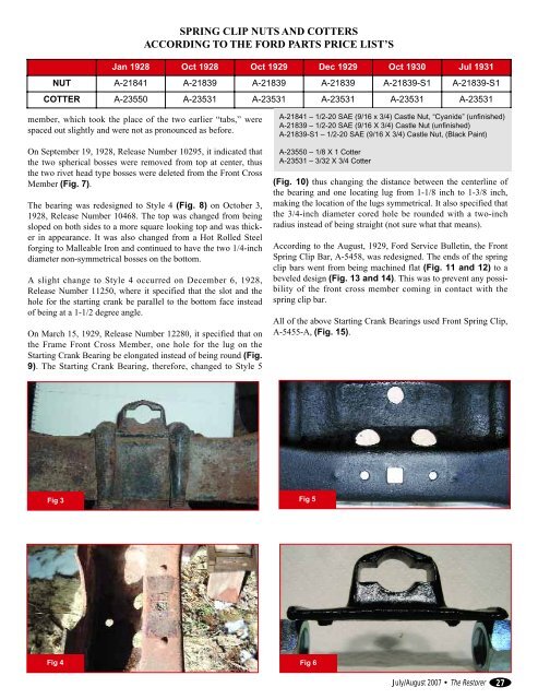
SPRING CLIP NUTS AND COTTERSACCORDING TO THE FORD PARTS PRICE LIST’SJan 1928 Oct 1928 Oct 1929 Dec 1929 Oct 1930 Jul 1931NUT A-21841 A-21839 A-21839 A-21839 A-21839-S1 A-21839-S1COTTER A-23550 A-23531 A-23531 A-23531 A-23531 A-23531member, which took the place of the two earlier “tabs,” werespaced out slightly and were not as pronounced as before.On September 19, 1928, Release Number 10295, it indicated thatthe two spherical bosses were removed from top at center, thusthe two rivet head type bosses were deleted from the Front CrossMember (Fig. 7).The bearing was redesigned to Style 4 (Fig. 8) on October 3,1928, Release Number 10468. The top was changed from beingsloped on both sides to a more square looking top and was thickerin appearance. It was also changed from a Hot Rolled Steelforging to Malleable Iron and continued to have the two 1/4-inchdiameter non-symmetrical bosses on the bottom.A slight change to Style 4 occurred on December 6, 1928,Release Number 11250, where it specified that the slot and thehole for the starting crank be parallel to the bottom face insteadof being at a 1-1/2 degree angle.On March 15, 1929, Release Number 12280, it specified that onthe Frame Front Cross Member, one hole for the lug on theStarting Crank Bearing be elongated instead of being round (Fig.9). The Starting Crank Bearing, therefore, changed to Style 5A-21841 – 1/2-20 SAE (9/16 x 3/4) Castle Nut, “Cyanide” (unfinished)A-21839 – 1/2-20 SAE (9/16 X 3/4) Castle Nut (unfinished)A-21839-S1 – 1/2-20 SAE (9/16 X 3/4) Castle Nut, (Black Paint)A-23550 – 1/8 X 1 CotterA-23531 – 3/32 X 3/4 Cotter(Fig. 10) thus changing the distance between the centerline ofthe bearing and one locating lug from 1-1/8 inch to 1-3/8 inch,making the location of the lugs symmetrical. It also specified thatthe 3/4-inch diameter cored hole be rounded with a two-inchradius instead of being straight (not sure what that means).According to the August, 1929, Ford Service Bulletin, the FrontSpring Clip Bar, A-5458, was redesigned. The ends of the springclip bars went from being machined flat (Fig. 11 and 12) to abeveled design (Fig. 13 and 14). This was to prevent any possibilityof the front cross member coming in contact with thespring clip bar.All of the above Starting Crank Bearings used Front Spring Clip,A-5455-A, (Fig. 15).Fig 3Fig 5Fig 4Fig 6July/August 2007 • The Restorer27