STARTING CRANK BEARING - Steve Plucker
STARTING CRANK BEARING - Steve Plucker
STARTING CRANK BEARING - Steve Plucker
- No tags were found...

You also want an ePaper? Increase the reach of your titles
YUMPU automatically turns print PDFs into web optimized ePapers that Google loves.
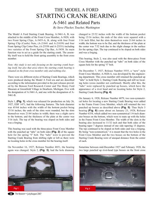
THE MODEL A FORD<strong>STARTING</strong> <strong>CRANK</strong> <strong>BEARING</strong>A-5461 and Related PartsBy <strong>Steve</strong> <strong>Plucker</strong>, Touchet, WashingtonThe Model A Ford Starting Crank Bearing, A-5461-A, B, wasattached to the middle of the Front Cross Member, A-5020, withtwo Front Spring Clips, A-5455-A, B, along with four FrontSpring Clip (Castle) Nuts, (A-21841 and A-21839) and fourFront Spring Clip Cotter Pins, (A-23550 and A-23531) includingtwo varieties of the Front Spring Clip Bar, A-5458. Its mainfunction was to act as a guide for the starting crank. The assemblyitself was to hold the front spring assembly to the front crossmember.Note: this study is not only focusing on the starting crank bearingitself, but also that area where the starting crank bearing issituated on the front cross member only and nothing else.There were six different styles of Starting Crank Bearings, whichwere produced during the Model A Ford era and are describedaccording to the information provided in the part releases providedby the Benson Ford Research Center and The Henry FordMuseum at Greenfield Village in Dearborn, Michigan. Five withthe designation of A-5461-A, and one with the designation of A-5461-B.Style 1, (Fig. 1), which was released for production on July 26,1927, EDF 1471, had the following features. The hole diameterwas 45/64 inches with the width of the bottom pocket being15/16 inches; the ends of the slots were rounded, but the slotsthemselves were 21/64 inches in width; there was a slight curveto the bottom; and the thickness of the plate at the center was3/16 inch. The top of the bearing was sloped on both sides andwas a forging.This bearing was used with the three-piece Front Cross Memberwith the punched up “tabs” on both sides (Fig. 2) of the squarehole for the spring “I” bolt. The “tabs” were to prevent theStarting Crank Bearing from shifting right or left as there wereno locating holes in the cross member for the bearing itself.On November 16, 1927, Release Number 4851, the bearingagain was changed. Style 2, (Fig. 3), had the hole diameterchanged to 23/32 inches with the width of the bottom pocketbeing 15/16 inches; the ends of the slots were squared with a1/16 inch fillet, but the slots themselves were 21/64 inches inwidth; the bottom was to be flat; and the thickness of the plate atthe center was 7/32 inch due to the slight change in the surfacefor the spring clips. The top continued to be sloped on both sidesand was a forging.This bearing, Style 2, was also used with the three-piece FrontCross Member with the punched up “tabs” on both sides of thesquare hole for the spring “I” bolt.On December 7, 1927, Release Number 5555, a “new” styleFront Cross Member, A-5020-A, was developed by the engineeringdepartment. This cross member still retained the punched up“tabs” to hold Style 2, Starting Crank Bearing and still no locatingholes (cross member not confirmed). Shortly after this, the“tabs” were replaced by punched up bosses, which have theappearance of a rivet head and no locating holes for Style 2,Starting Crank Bearing (Fig. 4).On January 6, 1928, Release Number 6079, two non-symmetricalholes for locating a new Starting Crank Bearing were addedto the Frame Front Cross Member, which still retained the twopunched up bosses as described above (Fig. 5). Thus Style 3bearing (Fig. 6) came about on January 23, 1928, ReleaseNumber 6354, which added two non-symmetrical 1/4-inch diameterbosses on the bottom, which were to mate up with the holesin the Frame Front Cross Member. The width of the slots in thebearing also increased to 11/32 inch and that both sides of thebearing taper 7 degrees instead of one side tapering 15 degrees.The top continued to be sloped on both sides and was a forging.By being “non-symmetrical,” it is meant that the two holes in theFront Cross Member and the two bosses on the bottom of theStarting Crank Bearing were of unequal distance from the centerof each.Sometime between mid-December 1927 and February 1928, thetwo large punched up rivet-head type bosses on the front crossFig 1 Fig 226 The Restorer • July/August 2007
SPRING CLIP NUTS AND COTTERSACCORDING TO THE FORD PARTS PRICE LIST’SJan 1928 Oct 1928 Oct 1929 Dec 1929 Oct 1930 Jul 1931NUT A-21841 A-21839 A-21839 A-21839 A-21839-S1 A-21839-S1COTTER A-23550 A-23531 A-23531 A-23531 A-23531 A-23531member, which took the place of the two earlier “tabs,” werespaced out slightly and were not as pronounced as before.On September 19, 1928, Release Number 10295, it indicated thatthe two spherical bosses were removed from top at center, thusthe two rivet head type bosses were deleted from the Front CrossMember (Fig. 7).The bearing was redesigned to Style 4 (Fig. 8) on October 3,1928, Release Number 10468. The top was changed from beingsloped on both sides to a more square looking top and was thickerin appearance. It was also changed from a Hot Rolled Steelforging to Malleable Iron and continued to have the two 1/4-inchdiameter non-symmetrical bosses on the bottom.A slight change to Style 4 occurred on December 6, 1928,Release Number 11250, where it specified that the slot and thehole for the starting crank be parallel to the bottom face insteadof being at a 1-1/2 degree angle.On March 15, 1929, Release Number 12280, it specified that onthe Frame Front Cross Member, one hole for the lug on theStarting Crank Bearing be elongated instead of being round (Fig.9). The Starting Crank Bearing, therefore, changed to Style 5A-21841 – 1/2-20 SAE (9/16 x 3/4) Castle Nut, “Cyanide” (unfinished)A-21839 – 1/2-20 SAE (9/16 X 3/4) Castle Nut (unfinished)A-21839-S1 – 1/2-20 SAE (9/16 X 3/4) Castle Nut, (Black Paint)A-23550 – 1/8 X 1 CotterA-23531 – 3/32 X 3/4 Cotter(Fig. 10) thus changing the distance between the centerline ofthe bearing and one locating lug from 1-1/8 inch to 1-3/8 inch,making the location of the lugs symmetrical. It also specified thatthe 3/4-inch diameter cored hole be rounded with a two-inchradius instead of being straight (not sure what that means).According to the August, 1929, Ford Service Bulletin, the FrontSpring Clip Bar, A-5458, was redesigned. The ends of the springclip bars went from being machined flat (Fig. 11 and 12) to abeveled design (Fig. 13 and 14). This was to prevent any possibilityof the front cross member coming in contact with thespring clip bar.All of the above Starting Crank Bearings used Front Spring Clip,A-5455-A, (Fig. 15).Fig 3Fig 5Fig 4Fig 6July/August 2007 • The Restorer27
Fig 7Fig 11Fig 8Fig 12Fig 9Fig 13Fig 10Fig 1428 The Restorer • July/August 2007
Contained in the July 1929 Ford Service Bulletin, it stated that “all startingcrank bearings, A-5461, now have a 5/16-inch oil hole through the lowerpart of the bearing.” This feature, however, was not mentioned in the FordPart Release of the part. The purpose of this hole was to “eliminate any possibilityof a squeak occurring between the Front Cross Member and thespring.” Some Starting Crank Bearings may have a hole for that purposedrilled on the face of the bearing which was done as a service job and notduring assembly.Fig 15By August, 1929, a new style Starting Crank Bearing, A-5461-B, Style 6,(Fig. 16), along with the “new” style Front Spring Clip, A-5455-B, (Fig.17), had come into play. It was referred to as “A-5461-B-Exp. Mfg.design.” It is not immediately known just when this part showed up on theassembly line, maybe with the introduction of the “new” style Frame FrontCross member, A-5020-B with the lowered radiator pads, but on January27, 1930, the “Exp. Mfg” was removed from the symbol numbers and itwas specified for full production on 1929-1930 A and AA Chassis. The partis also represented in the February 1930 Ford Service Bulletin as a “new”part and continued as such through production for use on vehicles with the10-leaf Front Spring Assembly.On July 1, 1930, Release Number 16984, the width of the section throughthe crank bearing hole was changed from 7/8 inch to 27/32 – 29/32 inch.On September 2, 1930, the locating lugs on the bottom of the bearing werechanged slightly from 1-3/8 to 1-25/64 inch of centerline of hole and centerlineof locating lugs.Fig 16Those vehicles that utilized a 12-leaf Front Spring Assembly, A-5310-B,had Front Spring Clip, A-5455-C, which was a longer clip. Those FrameFront Cross Members, which had the Cross Member Reinforcement, A-5347-R, added to them and for which also utilized the 12-leaf Front SpringAssembly, used Front Spring Clip, A-5455-DR which was longer yet.“CYANIDE” TREATED PARTSCyanide, which is considered a deadly gas, was also used in the treatmentof certain parts on the Model A such as nuts which were used in “highstressed”situations. Since external threads are rolled for strength, the internalthreads of nuts were machined via a tap thus making the two parts notcompatible strength wise. By treating the low carbon steel nuts in a hotcyanide bath of about 1,500º F, which creates a case hardened part, theproblem was solved getting the strength of the nuts closer to the rolledthreads. NOTE: FOR SAFETY REASONS, DO NOT TRY THIS PRO-CESS AT HOME! Besides the Front Spring Clip, other parts whereCyanide hardened nuts were used were the Front Spring Hangers, RearSpring Hangers, Crankshaft Front, Center, and Rear Bearing Bolts and theRear Axle Shaft.For a more precise view of actual “assembly” dates, please refer to theMARC/MAFCA Restoration Guidelines and Judging Standards, which isavailable through the Club, Model A Ford Club of America.Fig 17I would like to thank <strong>Steve</strong> Ciccalone and Fred Gooding for their contributionof pictures to this article. Also with further information, thanks to DougBraun, Jim Mason, Dennis Oberer, Tom Wesenberg, Chet Wojcik, and DonGibbard. You can also view this article in the Frame section on my websiteat www.plucks329s.org. If you have additional information, please emailme at steve@plucks329s.org.July/August 2007 • The Restorer29