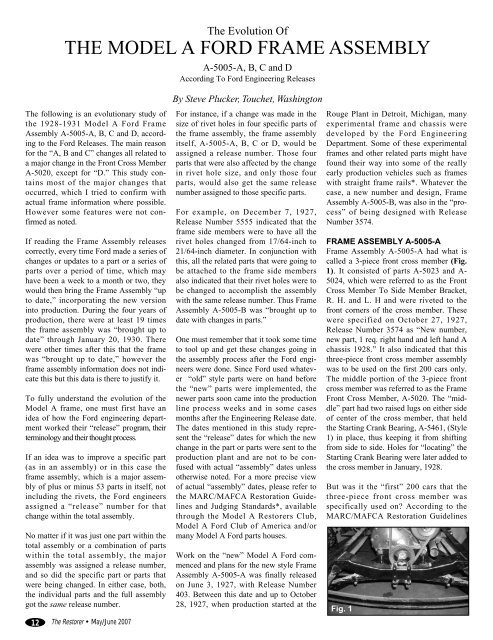
THE MODEL A FORD FRAME ASSEMBLY - Steve Plucker
THE MODEL A FORD FRAME ASSEMBLY - Steve Plucker
THE MODEL A FORD FRAME ASSEMBLY - Steve Plucker

Create successful ePaper yourself
Turn your PDF publications into a flip-book with our unique Google optimized e-Paper software.
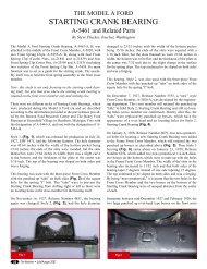
Fig. 5(Fig. 5) and Frame Center Cross Member,A-5025, in that the width of the lugs andsquared holes in the rear side changedfrom 1 inch to 1-1/4 inches, thus changingthe distance between the top of the crossmember and the top of the lugs from 2inches to 1-3/4 inches. The other majorchange was that all the holes for rivetingthe parts to the frame were changed from17/64 inch to 21/64 inch.By January 5, 1928, Release Number6079, Ford started to revert to the originalrivet size of 17/64-inch diameter on certainselect parts, including the Front CrossMember, which also “changed location ofsix rivet holes in the top.” In conjunctionwith this release, two non-symmetricalholes were added to the front cross member(see Fig. 5) for locating the StartingCrank Bearing, A-5461, which led to anew bearing, (Style 2), with two 1/4-inchbosses or lugs on the bottom of the partlater in the month. The first StartingCrank Bearing (Style 1) had no lugs on thebottom of the part. It is not known justhow far into early 1928 that the FrontCross Member with the two “lugs” thatwere on the cross member to prevent theStarting Crank Bearing (Style 1) frommoving right or left lasted. However,sometime after the “lugs” were deleted onthe front cross member, two “domed”bosses were stamped into the cross memberin place of the “lugs” and wereremoved sometime in mid 1928. Theframe assembly was thus “brought up todate with changes in parts.”January also saw changes in the rectangularholes in the Rear Engine SupportBracket (Fig. 6). On some of the veryearly brackets, these holes did not exist asviewed on Tudor A2157. Whether it wasFig. 614The Restorer • May/June 2007an error in the stamping process or not isnot known. However when they wereadded, the holes were very close to theFlywheel Housing attachment. With theJanuary 13, 1928, Release Number 6526,it indicated that the two rectangular holeswere moved out 1/4 inch, changing thedistance between the holes and the insideof the support from 1/4 to 1/2 inch. Alsothe Brake Retracting Spring Stud was tobe removed from the left Frame SideMember because of a change to the newstyle Hand Brake Lever Retracting Spring,A-2744, in place of the EqualizerOperating Shaft Retracting Spring, A-2492, as was related in the February 15,1928 Indianapolis Ford Service Letter dueto “the new style brake rod support.”Thus, on January 25, 1928, the frameassembly was once again “brought up todate with changes in the side members.”Fig. 7Fig. 8On February 21, 1928, the Hood ShelfSupport Bracket A-5100 went from threeholes (Fig. 7) to two holes (Fig. 8) on thetop flange of the bracket and the CenterCross Member rivet holes reverted back to17/64 inch. Bolt holes along with a greasezerk hole started to show up on the FrameSide Members right and left for the newstyle Emergency Brake Cross Shaft A-2828. The change over to the separateemergency brake system began as early asFebruary, 1928 in some plants, but mayhave been as late as March, 1928 as indicatedby the addition of the holes in theMarch 20 Release Number 7760. This wasfollowed by the removal of the holes forthe Brake Retracting Spring A-2492 on theback side and the removal of the holes forthe Dual High Control Bracket on thefront side of the Center Cross Member.On March 1, 1928, the holes for the handand foot brake rods were also increasedfrom 1 inch to 1-1/8-inch diameter. Marchalso saw a change in the location of the“squeeze grip” Emergency Hand BrakeLever Assembly from the left side of thechassis to going directly in front of thegear shift. With this came a change in thefront face of the Center Cross Memberwith the addition of new holes for theEmergency Brake Lever to Cross ShaftRods. On March 20, 1928, ReleaseNumber 7760, saw a change in size of therivet holes for the Front Cross Member,Hood Shelf Support Bracket, Front BrakeRod Spring Bracket, and Rear CrossMember revert back to 17/64 inch and theframe assembly was “Brought up to datewith changes in parts.”According to the April 10, 1928, ReleaseNumber 8164, and the September 6, 1928Fargo Ford Service Letter, the punched instop brackets on the back side of theCenter Cross Member, were discontinuedwhen the change to the solid brake rodswere made as they were no longer needed,or so they thought. Also a one-inch diameterhole was added to the back side of theCenter Cross Member for the clearing ofthe lever to cross shaft rod link. Onceagain, the frame assembly was “broughtup to date with changes in the side membersand the center cross member.” By theend of April the angle of the Front BrakeRod Spring Bracket surface and face forthe spring was also changed from 90degrees to 85 degrees.The major change in May, 1928 was thechange in location of the hole for attachingthe Battery to Ground ConnectorAssembly A-14301 to the frame. Fromstart of production to May, 1928, vehicleshad the negative battery post on the leftfront, making the positive post on the rightrear of the battery. The hole in the CenterCross Member for the ground strap wasdirectly behind this post. When the batteryterminals were changed to the oppositeconfiguration, the negative terminal wentto the right front and the positive terminalwent to the left rear, thus a new hole wasdrilled in the front of the Center CrossMember for the ground strap.By June, 1928, the changeover to the separateemergency brake system and the relocationof the Emergency Hand BrakeLever Assembly was complete*. This wasfeatured in the July, 1928 Ford Service
Bulletin. The hole for the left handEmergency Brake Lever Bracket wasremoved from the left Frame SideMember on July 27, 1928, and the frameassembly was also “brought up to date.”On August 27, 1928, Release Number10070, Ford reverted back to the punchedin stop brackets, which were located onthe back side of the Center Cross Member.This feature continued into December,1928. Those Center Cross Members,which do not have the punched in stopsfrom April to September, 1928, may verywell have added Brake Back Stop A-2476to the back of these cross members. It wasdiscovered that it was possible that withoutthe punched in brake stops, the brakeequalizer could come out of the brakeoperating shaft, thus the addition of theBrake Back Stop as related in theSeptember 6, 1928, Fargo Ford ServiceLetter. On the other hand, there are CenterCross Members without this feature wherethe owner or the local service departmentdidn’t put the part on the car. This was a“service” addition and was not done in thefactory or on the assembly line that I amaware of. Thus the frame assembly was“brought up to date.” A new hole for the“new” design Battery Support was alsoadded to the frame Center Cross Member.This was reported in the October, 1928Ford Service Bulletin.Fig. 9By August 30, 1928, Release Number10103, the Front Brake Rod SpringBracket, the Frame to Body Bracket –Front and the Hood Shelf Support Bracketwere all changed from a forging to astamping. September 20, 1928, the Frameto Engine Rear Support Plate, A-5095-A1,was changed from a forging to a casting orMalleable Iron Design (Fig. 9). It isthought that the “forged” plates have“raised” part numbers on the outer face ofthe plate where the “castings” have a“stamped” part number on the back of theplate. By September 21, 1928, ReleaseNumber 10155, the pockets and the holesfor the brake equalizer, holes for the handbrake rod and the holes and punched instops for the brake equalizer beam stopFig. 10were to be removed from the Center CrossMember. This feature began when thenew one-piece Service Brake Cross ShaftAssembly A-2485-D was introduced inNovember, 1928. On September 28, 1928,Release Number 10423, the Front andRear Running Board Brackets were to bechanged from a forging to pressed steel.Do not be surprised to find a combinationof forged and pressed steel brackets onthese frames. By March 1929, most, if notall, brackets were of the stamped steeldesign*.In October, the Ford engineers were workingon revising Frame Assembly, A-5005-B (Style 1). By October 11, 1928, ReleaseNumber 10580, Frame Assembly, A-5005-B (Style 2), was “brought up to datewith changes necessitated by the newfront engine support” (Fig. 10). WhatFord did was revise the Front CrossMember so that the back of the rear flangewas to be cut off 1-3/4 inches, thusremoving the engine support holes whichled to a new part, the Engine FrontSupport Assembly, A-6030-A. The size ofthe hole in the bottom of the cross memberwent from 1/2 inch to 3/4 inch diameter,which was used to accept the A-6034brass bushing for the new engine supportand the two holes formerly used with theengine pans were removed. The StartingCrank Bearing was also “redesigned”(Style 3), but retained the non-symmetricallugs. The new cross member and relatedparts were brought forth in theNovember, 1928 Ford Service Bulletinthus Frame Assembly, A-5005-B (Style2), began.On October 26, 1928, Release Number10580 Supplement, saw yet anotherchange in the Front Cross Member (Fig.11). To simplify the dies, the reinforcingribs were removed from the rear flangeand the radius for the notch on top of theflange on the rear side was changed from1-1/8 to 1-1/4-inch radius. Thus the beginningof Frame Assembly, A-5005-B (Style 3).Fig. 11By November, 1928, the one-pieceService Brake Cross Shaft Assembly, A-2485-D, was introduced and the need forthe square holes on the top side of theCenter Cross Member for the two piecebrake cross shaft and equalizer beam andthe square punched in stop brackets on theback of the cross member were no longerneeded and were removed thus the frameassembly was “brought up to date withchanges in parts.”On December 12, 1928, the hole in thebottom of the Front Cross Member, A-5020-A, for the motor support, waschanged from 3/4 inch to 7/8 inch thuseliminating the brass bushing. The hole inthe front face of the Center Cross Memberfor the brake rod was changed from a 1-1/2-inch hole to the shape of a blank platefor the frame front bumper plates (notconfirmed).Ford was ahead of its time duringDecember, 1928. According to ReleaseNumber 11397 for December 19, 1928,the Ford engineers were already looking ata “new” style Emergency Brake CrossShaft. The release indicated “Removedhole for Emergency Brake Cross ShaftLubricator Fitting and added hole andpocket for cross shaft bushing.” The “holeand pocket” in the Frame Side Membersfor this feature did not appear in productionwith the “new” shaft until April,1930.By January 26, 1929, Release Number11800, Ford changed the distance betweenthe hole for the muffler bracket and theoutside of the Frame Side Member—Right due to the “new” Muffler OutletPipe Clamp, A-5256-C. This changeappears in the March, 1929 Ford ServiceBulletin, page 327.January 30, 1929 Release Number 11861,the Front Cross Member was once againchanged to a fifth style, because it “addedtwo bosses 5/32-inch high around holesfor radiator bolts and changed shape at topof rear flange.” In viewing differentMay/June 2007 • The Restorer15
Fig. 12frames in this time period and earlier, onewill see that when placing a ruler on top ofthe frame going directly over the radiatormounting pad, you will see about an 1/8-inch gap. In viewing later frames, anddoing the same process, there is no gapsince the pad is flush with the top part ofthe frame. Thus Frame Assembly A-5005-B (Style 4) came about sometime afterMarch, 1929. Could this be the reason forthe new radiator mounting bolts asexplained in the September, 1929 FordService Bulletin, page 377? If so, this boltwent in conjunction with the Style 4 FrontCross Member change.In February, two of the holes for the batterysupport bracket were removed fromthe front flange of the Center Cross Member.March 15, 1929, Release Number 12280saw a change in the Front Cross Memberthat “specified that one hole for lug onstarting crank bearing be elongated insteadof being round” (Fig. 12). This constituteda change in the Starting Crank Bearing, A-5461, (Style 4), in that it “changed distancebetween centerline of bearing andone locating lug from 1-1/8 to 1-3/8 (inch),making location of lugs symmetrical.”On April 6, 1929, the top flange and holesfor fastening the body to the Frame toBody Bracket – Front, A-5075 wasredesigned (not confirmed).In May, the 3/4 inch hole for theEmergency Hand Brake Lever to CrossShaft Rod was removed from the rear faceof the Center Cross Member. By July 22,1929 Release Number 13488, two sets ofFig. 14holes each consisting of three 17/64 inchholes for the “new” style stop light switch,were added to the rear face of the CenterCross Member. This “new” switch cameinto production in October, 1929*. TheFord Service Bulletin for January, 1930,page 416 shows the attachment of theswitch to the rear cross member. It wasalso specified that two punched out slugsfrom the top of the Center Cross Member(Fig. 13) were to be used for blanks informing the Front Brake Rod SpringBrackets, A-2504. This, however, wasimplemented about September, 1929.By the end of August, 1929, the number ofholes to attach the Front Fender Bracketswere changed from three to four on thefront of the Frame Side Members toaccommodate a new style fender bracket.This bracket, however, took only two boltsto hold it to the frame. Only one hole wasadded and that was directly above thelower most hole for the old bracket. Thisfeature was included in the November,1929 Ford Service Bulletin, page 394.On September 4, 1929, Release Number13857, the width (length) of the horizontalpad on the Hood Shelf Support Bracketwas changed from 1-3/4 inches to 2-3/32Fig. 15inches and the length of the two slottedholes went from 3/16 inch to 19/32 inch(Fig. 15).<strong>FRAME</strong> <strong>ASSEMBLY</strong> A-5005-CWith the incorporation of the sixth styleFront Cross Member A-5020-B (Fig. 14),on September 30, 1929, Release Number14053 Frame Assembly A-5005-B was“superceded by A-5005-C for productionand service.” Where the radiator mountingpad on Frame Assembly A-5005-B (Style4), was “raised,” or flush with the frame,the new Front Cross Member on FrameAssembly A-5005-C, had lowered thisarea to become “recessed.” This featureshows up in the October, 1929 FordService Bulletin, page 387. October sawthe Frame to Engine Rear Support Platebecame a steel stamping with clipped corners(Fig. 16).December 5, 1929, saw the addition of a7/8 inch hole on the Front Cross Memberfor the radiator overflow tube. By January,1930, it was specified that the holes for thewheel carrier be drilled in place and thatall frames were to be center punched toshow the location of the holes (Fig. 17).January 30, 1930, specified the newStarting Crank Bearing, A-5461-B, (Style5), “for full production on 1929-30 A andAF Chassis.” This “new” Starting CrankBearing saw it’s beginning as an “Exp.Mfg.” experimental manufacturing in lateAugust, 1929. Not sure when it made itsappearance on the assembly line althoughit shows up in the February, 1930 FordService Bulletin as a “new” part.Fig. 17Fig. 1316 The Restorer • May/June 2007Fig. 16Fig. 18
Fig. 19In April, the second design EmergencyBrake Cross Shaft was implemented ontothe chassis. This design apparently hadbeen thought of way back in December,1928. It required a major change in theFrame Side Members in which the hole forthe Emergency Brake Cross ShaftLubricator Fitting was removed. The holewas made larger with the addition of a“pocket” in the side members for the crossshaft bushing. Included in this change wasthe addition of a hole on the back side ofthe Center Cross Member to attach theEmergency Brake Cross Shaft SupportBracket to. The shaft extended through theholes on both sides of the frame. This featureshows up in the April, 1930 FordService Bulletin, page 449.July saw the removal of the upper hole forthe Front Fender Bracket, which wasadded back in August of 1929. There wasalso the relocation of the four lower rivetholes for attaching the bottom flange ofthe Front Cross Member to the Frame Sidemembers (not confirmed).<strong>FRAME</strong> <strong>ASSEMBLY</strong> A-5005-DOn September 18, 1930, Release Number17050 Supplement #18 saw the BodyBracket on Frame – Front move to the rear2-3/8 inches (Fig. 18). Ford decided to“number” the holes in the frame for the“convenience in identifying holes.” Theproper numbering of these frame holes canbe found in the MARC/MAFCARestoration Guidelines and JudgingStandards. The release also indicated theaddition of Frame Assembly A-5005-D.Frame Assembly A-5005-D differed fromFrame Assembly, A-5005-C in only onemajor aspect and that was A-5005-D hadthe addition of the Frame Body Bracket #6Body Bolt, A-5076. It was located just infront of the rear running board bracket(Fig. 19). This frame was assigned to theStandard Fordor Sedan 160-A, the TownSedan 160-B and the Victoria 190-A.Frames without this bracket may be centerpunched to show the location.The May 16, 1931, Release Number19799 specified that the foot of theRunning Board Brackets be revised in thatribs be put on each side of the top rivethole to increase the strength and preventbreakage “as soon as the dies can bemade.” Three more cars were added to thelist for Frame Assembly A-5005-D inMay, 1931. Those were the DeluxeFordor Sedan, 160-C, the Town CarDelivery 295-A, and the ConvertibleSedan 400-A. The frame has also beenassociated with the Cabriolet 68-C, butwas never mentioned in any of the Fordreleases that were reviewed.I would like to thank the following peoplewho contributed many pictures for thisarticle: Doug Braun, Floyd Breech, KevinFehr, Don Gibbard, Fred Gooding, JimMason, Richard Miller, Tom Moniz, Peter“Swampy” Noyes, Roger Van Houten andThomas Wesenberg. I would also like tothank the many of you who have submittedframe information that is included onmy Web site, www.plucks329s.org.Without your information, this studywould have been impossible. I would alsolike to thank the Henry Ford Museum andGreenfield Village Research Center andthe Benson Ford Research Center for allthe data that was provided.* see the MAFCA/MARC RestorationGuidelines and Judging Standards.May/June 2007 • The Restorer17