Ultrasonic Debridement of Root Canals ... - The Endoexperience
Ultrasonic Debridement of Root Canals ... - The Endoexperience
Ultrasonic Debridement of Root Canals ... - The Endoexperience

Create successful ePaper yourself
Turn your PDF publications into a flip-book with our unique Google optimized e-Paper software.
0099-2399/88/1410-0486/$02.00/0<br />
JOURNAL OF ENDODONTICS<br />
Copyright 9 1988 by <strong>The</strong> American Association <strong>of</strong> Endodontists<br />
<strong>Ultrasonic</strong> <strong>Debridement</strong> <strong>of</strong> <strong>Root</strong> <strong>Canals</strong>: Acoustic<br />
Cavitation and Its Relevance<br />
M. Ahmad, BDS, MDSc, T. R. Pitt Ford, BDS, PhD, FDSRCPS, L. A. Crum, BS, MS, PhD, and<br />
A. J. Walton, BA, MSc, PhD<br />
<strong>The</strong> phenomenon <strong>of</strong> cavitation was investigated in<br />
an Enac-Osada ultrasonic unit using a #15 Cavi-<br />
Endo file 25-mm long. <strong>The</strong> observed cavitation was<br />
incorporated in a subsequent study which investi-<br />
gated the effects <strong>of</strong> cavitation on debridement, One<br />
group <strong>of</strong> 10 teeth was subjected to the cavitating<br />
file while a second group served as a control. Scan-<br />
ning electron microscopic observations revealed<br />
that there was no difference in cleanliness between<br />
the two groups <strong>of</strong> teeth studied. Cavitation might<br />
have resulted in the formation <strong>of</strong> pits in some <strong>of</strong> the<br />
canals and should not be regarded as an important<br />
mechanism in debridement.<br />
<strong>The</strong> recent introduction <strong>of</strong> ultrasonic root canal instruments<br />
into the endodontic armamentarium has attracted consider-<br />
able interest and controversy. Several studies have highlighted<br />
the ability <strong>of</strong> the instrument to produce cleaner canals com-<br />
pared with conventional hand instrumentation (1, 2), while<br />
others have stressed the inherent difficulties in ensuring total<br />
debridement <strong>of</strong> root canals (3, 4). One attractive feature <strong>of</strong><br />
this instrument lies in its flow-through irrigation system which<br />
is an undoubted advantage over hand instruments. <strong>The</strong> pre-<br />
dominant mode <strong>of</strong> action responsible for its acclaimed supe-<br />
rior debridement ability as well as disruption <strong>of</strong> bacteria has<br />
been linked to the phenomenon <strong>of</strong> cavitation (5, 6). A recent<br />
study (7) has discounted the role <strong>of</strong> cavitation in one ultra-<br />
sonic unit (Cavi-Endo; Caulk, Dentsply, York, PA). In view<br />
<strong>of</strong> the emphasis placed on the role <strong>of</strong> cavitation in debride-<br />
ment by the proponents <strong>of</strong> the technique, this study was<br />
undertaken to throw further light onto this phenomenon by<br />
examining its role in ultrasonic debridement using a different<br />
ultrasonic unit (Enac-Osada, Tokyo, Japan).<br />
<strong>The</strong> investigation was a three-part study. <strong>The</strong> first part<br />
involved measuring the range <strong>of</strong> displacement amplitude<br />
generated by files driven in the Enac unit in order to determine<br />
the most effective amplitude range, type, and size <strong>of</strong> file that<br />
could generate cavitation. <strong>The</strong> second part involved detection<br />
<strong>of</strong> cavitation using the selected file driven in the Enac unit.<br />
<strong>The</strong> final part <strong>of</strong> the investigation assessed the effectiveness<br />
<strong>of</strong> the observed cavitation on debridement <strong>of</strong> root canals.<br />
486<br />
MATERIALS AND METHODS<br />
Printed in U.S.A.<br />
VOL. 14, NO. 10, OCTOBER1988<br />
Displacement Amplitude Measurements<br />
A preliminary study that was performed revealed that a<br />
total <strong>of</strong> 10 hand K files (Zipperer, Munchen, West Germany)<br />
fractured when driven in the Enac unit. It was decided there-<br />
fore to use Cavi-Endo files with the Enac unit. <strong>The</strong> experi-<br />
mental arrangement for the measurement <strong>of</strong> the displacement<br />
amplitude has been described previously (8). <strong>The</strong> tip <strong>of</strong> the<br />
file was viewed under a traveling microscope at a magnifica-<br />
tion <strong>of</strong> x l00 and illuminated from the side such that a pin-<br />
point source <strong>of</strong> light was observed at the very tip. When the<br />
file was set into oscillation, this light was visible as a thin<br />
transverse line, half <strong>of</strong> which gave the value <strong>of</strong> the transverse<br />
displacement amplitude. Cavi-Endo K flies <strong>of</strong> sizes 15 and<br />
20, each 29-mm long, and size 25 (25-mm long) were inves-<br />
tigated at power settings ranging from 1.0 to 3.5. It was<br />
decided to investigate up to power 3.5, although the maxi-<br />
mum power setting recommended for endodontic purposes<br />
indicated on the unit was 3.0. For each file investigated, five<br />
readings were obtained and the mean derived. Preliminary<br />
results showed that a #15 file, 29-mm long, displayed the<br />
highest range <strong>of</strong> values. This size was further examined at a<br />
different length; 4 mm <strong>of</strong> the coronal end <strong>of</strong> the file was<br />
removed leaving a file 25-mm long, a length used commonly<br />
in clinical practice. Three files at this length were examined<br />
for their displacement amplitude as described previously.<br />
Detection <strong>of</strong> Cavitation<br />
When the file was vibrated in a liquid medium, the acoustic<br />
energy was carried through the liquid by the back and forth<br />
motion <strong>of</strong> the molecules along the direction <strong>of</strong> propagation.<br />
This produced alternate compressions and rarefactions in<br />
pressure.<br />
At a certain threshold displacement amplitude <strong>of</strong> the file<br />
and at a critical value <strong>of</strong> the negative acoustic pressure am-<br />
plitude, dependent on the liquid's local conditions <strong>of</strong> temper-<br />
ature, viscosity, dissolved gas content, and microscopic par-<br />
ticulate content, the tensile strength <strong>of</strong> the liquid was exceeded<br />
and a vapor cavity was formed. <strong>The</strong> subsequent positive<br />
pressure phase <strong>of</strong> the acoustic field then forced this vapor-<br />
filled cavity to implode, thereby converting the potential<br />
energy gained in growth into a concentrated region <strong>of</strong> kinetic<br />
energy as the cavity collapsed. This phenomenon was very
Vol. 14, No. 10, October 1988<br />
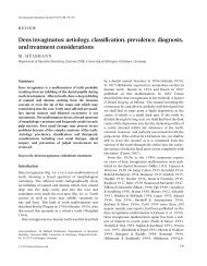
FIG 1. Apical haft <strong>of</strong> the file viewed under the image intensifier lens<br />
(,4, apical end). <strong>The</strong> file was illuminated with a low level external<br />
source <strong>of</strong> light and shows several spots where light was strongly<br />
reflected from its surface.<br />
efficient in energy concentration and extremely high temper-<br />
atures and pressures could be generated. It should be noted<br />
that in the authors' definition <strong>of</strong> cavitation described here,<br />
they refer only to "transient cavitation" as the phenomenon<br />
<strong>of</strong> interest. A related effect, called "stable cavitation" was<br />
associated with gas bubble production and oscillation and was<br />
not an efficient energy concentration mechanism. When tran-<br />
sient cavitation occurred, the cavity collapses were so violent<br />
that visible light emission could be observed.<br />
This light emission could be detected by a sensitive image<br />
intensification technique which allowed observations <strong>of</strong> the<br />
spatial and temporal distributions <strong>of</strong> the light (9).<br />
<strong>The</strong> file which was shown in the first part <strong>of</strong> the study to<br />
generate maximum displacement amplitude (#15 file, 25-ram<br />
long, see "Results") was used in the experiment to detect<br />
cavitation. <strong>The</strong> experimental arrangement was similar to that<br />
which has been described in an earlier study (7).<br />
<strong>The</strong> file under investigation was immersed in a container<br />
measuring 100 mm x 50 mmx 100 mm containing tap<br />
water. <strong>The</strong> lens <strong>of</strong> the image intensifier viewed a circular area<br />
<strong>of</strong> approximately 100 mm 2 at the apical half <strong>of</strong> the file, the<br />
tip <strong>of</strong> the file positioned at the 11 o'clock position <strong>of</strong> the lens<br />
(Fig. 1). <strong>The</strong> power setting was slowly increased from 1.0 to<br />
3.5. Light emissions from the irradiated liquid were focused<br />
by a lens system onto the input photocathode <strong>of</strong> an EMI Type<br />
9912 image intensifier tube. <strong>The</strong> input photons released pho-<br />
toelectrons from the input photoeathode, which were then<br />
multiplied in number and energy as they traversed the tube<br />
and were subsequently recorded as discrete spots on the<br />
output phosphor <strong>of</strong> the tube. <strong>The</strong> phosphor was viewed by a<br />
video camera, recorded on magnetic tape, and displayed<br />
simultaneously on a television monitor. A polaroid camera<br />
was used to record features <strong>of</strong> interest observed on the mon-<br />
itor.<br />
Investigation <strong>of</strong> the Role <strong>of</strong> Cavitation in <strong>Ultrasonic</strong><br />
<strong>Debridement</strong> <strong>of</strong> <strong>Root</strong> <strong>Canals</strong><br />
To investigate the effects <strong>of</strong> cavitation on debridement, it<br />
was necessary to simulate the conditions at which cavitation<br />
was detected. <strong>The</strong> file should vibrate in the root canal at a<br />
<strong>Ultrasonic</strong> Debddement <strong>of</strong> <strong>Root</strong> <strong>Canals</strong> 487<br />
W//2 ',<br />
,, y," y],<br />
f Y,/') t<br />
t ,1/ 1~ I<br />
I /I /I \<br />
) IV',~ l<br />
D- 2r<br />
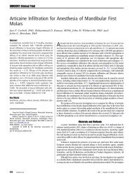
FIG 2. Diagrammatic representation to show the minimal width to<br />
which the canal should be enlarged in order to ensure cavitation (~o,<br />
displacement amplitude <strong>of</strong> the file; d, diameter <strong>of</strong> the tip <strong>of</strong> the file; D,<br />
diameter <strong>of</strong> the root canal).<br />
displacement amplitude for cavitation inception. This corre-<br />
sponded to a value <strong>of</strong> 135 um (see "Results"). To provide<br />
ample space for the cavitating file to vibrate freely without<br />
any restriction from the canal walls, it was necessary to ensure<br />
that the width <strong>of</strong> the root canal was equal to or more than<br />
the sum <strong>of</strong> the diameter <strong>of</strong> the tip <strong>of</strong> the cavitating file (#15)<br />
and twice the displacement amplitude (Fig. 2). This minimal<br />
width could be achieved by enlarging the canal to a #40 file.<br />
Twenty freshly extracted maxillary canines with straight roots<br />
and large canals, stored in saline, were used in this part <strong>of</strong> the<br />
study. Access was achieved through the crown <strong>of</strong> each tooth.<br />
<strong>The</strong> canal was ultrasonically filed with a copious flow <strong>of</strong> 2.5 %<br />
NaOCl using files <strong>of</strong> sizes 15, 20, 25, 2 rain for each instru-<br />
ment driven in the Cavi-Endo unit. <strong>The</strong> latter was used as the<br />
Enac unit under investigation, had no provision for sodium<br />
hypochlorite. <strong>The</strong> coronal aspect <strong>of</strong> the canal was then filed<br />
with a #35 diamond file until the width <strong>of</strong> the canal allowed<br />
at least a #40 file to be negotiated to the full length <strong>of</strong> the<br />
canal. Upon completion <strong>of</strong> instrumentation, the teeth were<br />
randomly divided into two groups, each <strong>of</strong> l0 teeth.<br />
To ensure that the file would vibrate freely without con-<br />
tacting the walls <strong>of</strong> the root canal, the crowns were removed<br />
from the roots. For the first group <strong>of</strong> 10 teeth (cavitation<br />
group), the file which was found to generate cavitation (see<br />
"Results") was positioned until the tip reached the middle<br />
third <strong>of</strong> the canal. This was done as it was impossible to<br />
ensure a completely free contact from the canal walls while<br />
oscillating if the file was placed to the full working length.<br />
<strong>The</strong> power setting on the Enac unit was turned on at 3.5 and<br />
the file was allowed to vibrate with free flow <strong>of</strong> 2.5% NaOCI<br />
for 5 rain. <strong>The</strong> latter was delivered to the coronal aspect <strong>of</strong><br />
the tooth via a plastic tube tied to lhe ultrasonic handpieee<br />
and connected to the Cavi-Endo reservoir.<br />
<strong>The</strong> second group <strong>of</strong> 10 teeth (no cavitation) received the<br />
same treatment but the file was vibrated at a lower power<br />
setting <strong>of</strong> 1.0 at which no light emission was observed. After
488 Ahmad et al.<br />
completion <strong>of</strong> these procedures, the teeth were split into halves<br />
with a mallet and a chisel, coded, dried for 24 h, and sputter<br />
coated with gold for viewing under a scanning electron micro-<br />
scope. Observations <strong>of</strong> the canal surfaces were made at the<br />
coronal, middle, and apical thirds <strong>of</strong> the canal at various<br />
magnifications. Evaluation <strong>of</strong> debridement was carded out by<br />
the first author through blind scoring separately, the smear<br />
layer and the superficial debris remaining on the canal sur-<br />
faces at the coronal, middle, and apical thirds at magnification<br />
x800. Prior to scoring, photographs <strong>of</strong> the representative areas<br />
<strong>of</strong> canals at x800 were taken to represent the gradations <strong>of</strong><br />
"~" '- /" .." ~'- " "~i'<br />
-~,,_ _ -~ . ....a~ ~ ".:.~ #:<br />
. ., t.~ ~ . ". a., ",<br />
-i '-<br />
~-.. ~-,,'-~ . ,~ .:_ -., ... :- .,,~,,<br />
~,'~,,~" ' " F ~ ' ~ ' ; ~'::.-:~*';~0 "" ~'L.-:.-,..~<br />
m<br />
%<br />
Journal <strong>of</strong> Endodontics<br />
the scoring system. This magnification was chosen because it<br />
showed the detail required while maintaining as large a field<br />
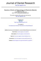
as possible. Four photomicrographs <strong>of</strong> the superficial debris<br />
at x800 (Fig. 3) and four <strong>of</strong> the smear layer at (Fig. 4)<br />
were used as reference standards during the subsequent scor-<br />
ing.<br />
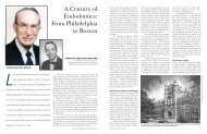
A scale <strong>of</strong> 0 to 3 was used to rank order the amount <strong>of</strong><br />
superficial debris and smear layer9 For the debris, a score <strong>of</strong><br />
0 represented no superficial debris, 1 minimal debris, 2 mod-<br />
erate debris, and 3 represented heavy amounts. For the smear<br />
layer, a score <strong>of</strong> 0 represented no smear layer with all tubules<br />
9 ,~.,. ,,,~ ~-'3 ~. ,.~ .. : , ~- .:.<br />
.- :.~.,. .... .': . 9 ., ., ~.~ r~'<br />
">.. "3S. ~, ~. s 9 .". . ,<br />
: '.'~S~ '- ,~.' ",,,4~ 9 :~-. ; ,~ r', .ar -,t- 7,: ~, ~ 9 r., ", ,<br />
"'"<br />
t:r~."<br />
to.<br />
.,I ! .<br />
}.. 9 - t<br />
5 .L: "<br />
I9<br />
, -c<br />
.~,,,. ~ ~:, :- " "~-.L"~, ~-~'<br />
.%.2 . .; *~-~ . ,,. ,,\ 9 ~ '~ : J<br />
(<br />
;' ~ "<br />
.4 "-I<br />
K<br />
-i<br />
I- " r~<br />
~t<br />
' 9 --T '" -, " " ' ' ~ '., -< :/J "'3~.<br />
I<br />
. ( , .~<br />
2.1 .~,1 4t o'~t - 9 - . " " r ~ " P-'.. 9 " :"--..~',-.. ~- "%..'~:- ' ~ "';, -~<br />
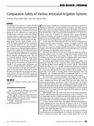
FIG 3. Reference photomicrographs showing the various gradations <strong>of</strong> debris used to score the specimens (original magnification x800). A,<br />
Score <strong>of</strong> 0. B, Score <strong>of</strong> 1. C, Score <strong>of</strong> 2. D, Score <strong>of</strong> 3.
Vol. 14, No. 10, October 1988 <strong>Ultrasonic</strong> <strong>Debridement</strong> <strong>of</strong> <strong>Root</strong> <strong>Canals</strong> 489<br />
i "<br />
*.. ,<br />
%.<br />
82 N. . .<br />
r. k ~ t-,..~<br />
9 ,... ~....-[ ',.,,,,<br />
1,2.~:-..".. -,' ,,,.~,,, .- ..., :-<br />
. ~ . ~ ..t.'_.r ,~.~~ 7 '"~ . " ", 9 .~. ,,:<br />
' "~ "" ;~;~ "~" '~'~ " ~ ,,.. 9 ~: ',., ;,. ~ 1~<br />
..dTt!" ~ - . . . . . ~, . . _ = a ~ . ' r " T " 't. *-: b<br />
C<br />
" ;: ., ,.-.<br />
. . . . . . , .., - . , %,,~s163<br />
[3<br />
,;" tf<br />
~, ~.<br />
9 - - ;i. -, " " ;" .~ :<br />
.: ft.-,"'- -<br />
, f<br />
.,v;." ;C" -'i': ~ " "<br />
ij ..... "" ', ..... eS- , '~ ..,<br />
9 [ ~ .u .a<br />
t",t .<br />
L2<br />
r t ~ . . 9 9<br />
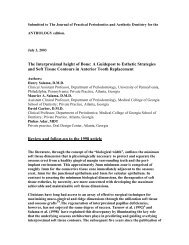
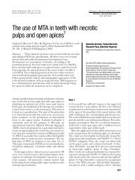
FIG. 4 Reference photomicrographs showing the various gradations <strong>of</strong> smear layer used to score the specimens (original magnification x800).<br />
A, Score <strong>of</strong> 0. B, Score <strong>of</strong> 1. C, Score <strong>of</strong> 2. D, Score <strong>of</strong> 3.<br />
opened, 1 little smear layer with more than 50% <strong>of</strong> the tubules<br />
opened, 2 moderate smear with less than 50% <strong>of</strong> the tubules<br />
opened, while 3 represented heavy smear with outlines <strong>of</strong><br />
tubules obliterated.<br />
For each group, the sum <strong>of</strong> the scores for a particular region<br />
<strong>of</strong> the root canal was calculated and divided by 10 to give the<br />
mean score. To calculate the overall score, the sum <strong>of</strong> the<br />
mean scores <strong>of</strong> the coronal, middle, and apical thirds were<br />
divided by three. In order to see if there were any differences<br />
between the degree <strong>of</strong>debridement in the two techniques, the<br />
t<br />
overall scores were statistically evaluated using the Mann-<br />
Whitney U test.<br />
RESULTS<br />
Displacement Amplitude Measurements<br />
<strong>The</strong> results <strong>of</strong> the displacement amplitude values <strong>of</strong> the<br />
files investigated are shown in Fig. 5. It is evident that increas-<br />
ing the power setting tended to increase the displacement
490 Ahmad et al.<br />
14o<br />
130<br />
120<br />
110<br />
100<br />
~ ~o<br />
[ so<br />
70<br />
60<br />
50<br />
40<br />
30<br />
~ 4~#<br />
20 " ~ , , ,<br />
0 t 1,5 210 2.5 3.0 315<br />
Power Setting (Machine units)<br />
J.<br />
15,25mm<br />
' # 15,29mm<br />
~'~ # 25,29rnm<br />
1<br />
# 20,29mm<br />
FIG 5. Transverse displacement amplitude values as a function <strong>of</strong><br />
power setting with different file sizes driven in the Enac unit (error<br />
bars +_ SO, n = 15).<br />
amplitude9 In general, the smaller files, #15, at both lengths,<br />
exhibited higher displacement amplitude than the other fdes.<br />
Shortening the # 15 file to 25 mm appeared to double the<br />
displacement amplitude for each power setting investigated.<br />
<strong>The</strong> highest value attained was 135 pm and this corresponded<br />
to the highest power setting investigated.<br />
Detection <strong>of</strong> Cavitation<br />
Light emissions occurred at power setting 3.5 and this<br />
corresponded to a displacement amplitude value <strong>of</strong> 135 ~zm.<br />
No emission occurred at lower power. Figure 6 shows the<br />
photograph taken from the television monitor displaying the<br />
phenomenon <strong>of</strong> light emission. Each small white spot re-<br />
corded on the photograph represents a single light photon. It<br />
was noted that the spots were grouped at the apical tip <strong>of</strong> the<br />
file occupying an area <strong>of</strong> approximately 0.7 mm ~. This light<br />
emission indicated that a violent form <strong>of</strong> cavitation had<br />
occurred in the region <strong>of</strong> the high concentration <strong>of</strong> spots.<br />
Scanning Electron Microscopic Observations<br />
No difference was apparent in the distribution and the<br />
amount <strong>of</strong> surface debris in the two groups <strong>of</strong> specimens (Fig.<br />
7, p = 0.9397). In general terms, the canals were clean (Figs.<br />
8 and 9), although debris could be observed to be distributed<br />
randomly throughout the length <strong>of</strong> the canals, particularly<br />
when viewed at high magnifications, Both groups exhibited a<br />
Q6 " ~<br />
9 ~ 9 k ,~ . .<br />
9 i::"I ,.., ,.<br />
Journal <strong>of</strong> Endodontics<br />
, ~ " , 9 . .: ,<br />
,. . .... :,,.<br />
I 9 =P<br />
FIG 6. Light emissions observed from the oscillating file. <strong>The</strong> individual<br />
spots are single photon events; the concentration <strong>of</strong> spots near the<br />
center (boxed) show regions <strong>of</strong> the file where cavitation was occur-<br />
ring. Almost all <strong>of</strong> the cavitation was associated with the apical end<br />
<strong>of</strong> the file. <strong>The</strong> single photon events that were randomly distributed<br />
are most likely due to electronic and thermal "noise."<br />
0 9<br />
u~0.6<br />
.~. o.s<br />
.1o<br />
~ 0.4-<br />
T Standard Deviation<br />
Cavitation<br />
] No Cavitation<br />
0.80.7 I =0.9397<br />
~ o.2 ~<br />
0.1 N ~ I<br />
Coronal Middle Apical Combined<br />
Mean Score<br />
FIG 7. Comparison <strong>of</strong> debris score for two different treatments<br />
measured for each third <strong>of</strong> 10 roots. Bars represent the mean debris<br />
score.<br />
typical smear layer appearance, particularly in the coronal<br />
third <strong>of</strong> the canal. At the middle and apical ends in both<br />
groups, there was less evidence <strong>of</strong> smearing, although the<br />
dentinal tubule openings were occluded. No statistically sig-<br />
nificant difference was observed in the smear layer scores<br />
between the two groups <strong>of</strong> specimens (Fig. 10, p = 0.5708).<br />
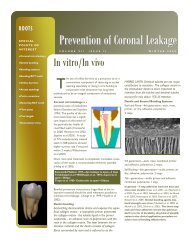
In the cavitation group <strong>of</strong> specimens, observations relating<br />
to areas in close vicinity to the apicat end <strong>of</strong> the file deserve<br />
comment. Four <strong>of</strong> the specimens exhibited irregularly distrib-<br />
uted small pits confined to the lower middle region <strong>of</strong> the<br />
canal (Fig. 11). <strong>The</strong> latter corresponded to the position <strong>of</strong> the<br />
apical end <strong>of</strong> the file when it vibrated freely in the canal.<br />
<strong>The</strong>se pits differed in size from each other but measured 40<br />
um in diameter. A typical feature <strong>of</strong> these pits was the virtual
Vol. 14, No. 10, October 1988 <strong>Ultrasonic</strong> <strong>Debridement</strong> <strong>of</strong> <strong>Root</strong> <strong>Canals</strong> 491<br />
FtG 8. A typical example <strong>of</strong> the middle third <strong>of</strong> a root canal subjected<br />
to a file vibrating at displacement amplitude for cavitation inception<br />
(power 3.5), scored as 1.0 for both debris and smear layer (original<br />
magnification<br />
FIG 9. A typical example <strong>of</strong> the middle third <strong>of</strong> a root canal subjected<br />
to file vibrating at power 1.0 (no cavitation), scored as 1.0 for both<br />
debris and smear layer (original magnification x500).<br />
absence <strong>of</strong> smear layer at the base <strong>of</strong> the pits, with the openings<br />
<strong>of</strong> the tubules clearly evident (Fig. 11 C). No more than 10<br />
pits were present in any one canal. <strong>The</strong> distribution <strong>of</strong> debris<br />
or smear layer around the vicinity <strong>of</strong> these pits did not vary<br />
o<br />
3.0<br />
2.5<br />
cn 2.0<br />
r, t.s<br />
~ 1.0<br />
o s<br />
Coronal<br />
,t<br />
Middle Apical<br />
T Standard Deviation<br />
[] cavi,,,ion<br />
--]No Cavitation<br />
Combined<br />
Mean Score<br />
p=0.5708<br />
FiG 10. Comparison <strong>of</strong> smear layer scores for two different treatments<br />
measured for each third <strong>of</strong> 10 roots. Bars represent the mean smear<br />
layer score.<br />
greatly from those canals in the control group. None <strong>of</strong> the<br />
specimens in the control group exhibited any <strong>of</strong> these pits.<br />
DISCUSSION<br />
<strong>The</strong> investigation has shown that it is possible to achieve<br />
transient cavitation from an ultrasonic file provided optimum<br />
conditions are satisfied and a certain threshold displacement<br />
amplitude is achieved. Although this partly confirms some <strong>of</strong><br />
the claims made by the manufacturers, it dispels the popular<br />
view that cavitation can occur during actual clinical proce-<br />
dures using the technique presently recommended for instru-<br />
mentation. <strong>The</strong> reasons for this are 2-fold. First, the threshold<br />
power setting at which this phenomenon would occur was<br />
found to be beyond the range that is normally used for<br />
endodontic purposes; the maximum power setting for endo-<br />
dontic purposes indicated on the unit was 3.0, while light<br />
emission was observed at a higher setting (3.5). Second and<br />
more important, for cavitation to occur in the root canal, the<br />
file must vibrate at a displacement amplitude <strong>of</strong> at least 135<br />
~m. This would be impossible to achieve in the clinical<br />
situation using the recommended technique <strong>of</strong> instrumenta-<br />
tion as the filing motion would dampen considerably the<br />
oscillatory motion <strong>of</strong> the file and its displacement amplitude.<br />
<strong>The</strong> conditions ideal for the formation <strong>of</strong> cavitation had to<br />
be simulated to ensure that cavitation' occurred. It meant that<br />
the root canals had to be enlarged to the size <strong>of</strong> a #40 file,<br />
which is approximately the minimum size that would permit<br />
clearance and free vibration <strong>of</strong> the # 15 f'de working at the<br />
threshold amplitude for cavitation inception. This factor car-<br />
ries a pr<strong>of</strong>ound clinical implication: cavitation can play little<br />
if any part in the cleaning <strong>of</strong> narrow canals. <strong>The</strong> result <strong>of</strong> the<br />
study to detect cavitation has clearly demonstrated that there<br />
was a spatial relationship between the apical end <strong>of</strong> the file<br />
and the cavitation phenomenon. This would seem advanta-<br />
geous in the clinical context, as it is <strong>of</strong>ten the apical end that<br />
is the most difficult to clean due to inaccessibility. However,<br />
it is evident from our experimental results that cavitation<br />
generated in some <strong>of</strong> the canals only resulted in the random<br />
formation <strong>of</strong> pits that were distributed far apart. Although the
492 Ahmad et al. Journal <strong>of</strong> Endodontics<br />
FIG 11. Pitting <strong>of</strong> canal surfaces (boxed) in the middle third region in teeth subjected to the eavitating file. A, C, cavitation pits (original<br />
magnification x30). B, Original magnification x500. C, High-power view <strong>of</strong> the pit showing exposed 0~mtinal tubules at its base (original<br />
magnification x1,500).<br />
base <strong>of</strong> each pit revealed patent tubules, cavitation appeared<br />
to be ineffective in removing the adjacent smear layer.<br />
<strong>The</strong>se crater-like pits could conceivably have been the result<br />
<strong>of</strong> implosion <strong>of</strong> cavitation bubbles, owing to their spatial<br />
relationship with the middle third <strong>of</strong> the canal (equivalent<br />
position <strong>of</strong> the tip <strong>of</strong> the cavitating file), although it would be<br />
difficult to prove conclusively. It may be argued that the pits<br />
represent mechanical damage from the vibrating file hiring<br />
the canal wall. This possibility cannot be discounted, but in<br />
view <strong>of</strong> the random and wide distribution <strong>of</strong> the pits, this<br />
would seem unlikely. Damage created by the tip <strong>of</strong> a vibrating<br />
file would only be confined to a small area as the instrument<br />
was clamped. <strong>The</strong> microerosion <strong>of</strong> solid surfaces in a cavitat-<br />
ing fluid is a well-established phenomenon (10, 11). Several<br />
authors (10, 12) have assumed the existence <strong>of</strong> tiny high-<br />
speed inwardly directed water jets inside the collapsing bub-<br />
bles. Such an asymmetrically collapsing bubble would cause<br />
pitting by a "water hammer" action when the water jets<br />
impinge upon a surface. When occurring in sufficient mag-<br />
nitude, cavitation can be put to good use as in the ultrasonic<br />
cleaning baths widely used in industry (11). In the root canal,<br />
this benefit would only be afforded provided that cavitation<br />
complexes are present in sufficient numbers and are well<br />
distributed throughout the length <strong>of</strong> the root canal to remove<br />
the smear layer significantly and expose patent dentinal tu-<br />
bules. In the present instrument design, the cavitation that<br />
would occur is minimal and sited almost exclusively at the<br />
apical end <strong>of</strong> the file where the displacement amplitude is at<br />
its maximum.<br />
<strong>The</strong> failure to detect any difference in cleanliness between
Vol. 14, No. 10, October 1988<br />
the two groups <strong>of</strong> specimens was not unexpected and further<br />
strengthened our view <strong>of</strong> the lack <strong>of</strong> importance <strong>of</strong> cavitation<br />
in cleaning. An earlier study by Ahmad et al. (8) had dem-<br />
onstrated that the main mechanism responsible for ultrasonic<br />
debridement was acoustic streaming. <strong>The</strong> latter may coexist<br />
with the presence <strong>of</strong> stable cavitation (9), a form <strong>of</strong> cavitation<br />
not investigated in this study.<br />
Only 4 <strong>of</strong> the 10 canals exhibited pitting. Assuming that<br />
pitting was due to cavitation, this illustrated the difficulty in<br />
ensuring the reproducibility <strong>of</strong> cavitation, even with condi-<br />
tions that attempted to be ideal.<br />
<strong>The</strong> inherent morphological variations in the shape <strong>of</strong> the<br />
root canals could have imposed constraints on the oscillation<br />
<strong>of</strong> the file. We emphasize that even under apparently optimal<br />
conditions which included ensuring a large unobstructured<br />
access with adequate enlargement <strong>of</strong> the canal, cavitation was<br />
difficult to reproduce.<br />
CONCLUSION<br />
Evidence has been presented on the generation <strong>of</strong> transient<br />
cavitation by the Enac ultrasonic unit. It has been shown that<br />
the inception <strong>of</strong> cavitation required a threshold amplitude <strong>of</strong><br />
at least 135 um generated by a freely vibrating file. This<br />
phenomenon could not occur during normal clinical instru-<br />
mentation using the recommended technique. However, by a<br />
slight modification <strong>of</strong> the technique a vibrating file could be<br />
made to generate cavitation in a root canal. Scanning electron<br />
microscopic comparisons between teeth subjected to cavita-<br />
tion and noncavitation techniques showed that there was no<br />
difference in cleanliness between the two groups. Cavitation<br />
might have resulted in the formation <strong>of</strong> pits on the surface <strong>of</strong><br />
some canals and should not be regarded as an important<br />
mechanism in debridement.<br />
This work was presented at the 44th Armual Meeti~x:j <strong>of</strong> the American<br />
Association <strong>of</strong> Endodontists, San Antonio, April 1987.<br />
<strong>Ultrasonic</strong> <strong>Debridement</strong> <strong>of</strong> <strong>Root</strong> <strong>Canals</strong> 493<br />
Dr. Ahmad acknowledges the grants from the University <strong>of</strong> Malaya and<br />
Public Services Department, Kuala Lumpur, Malaysia. Dr. Crum acknowledges<br />
the financial support <strong>of</strong> the Office <strong>of</strong> Naval Research, National Science Foun-<br />
dation, and National Institute <strong>of</strong> Health. Thanks are also due to the following<br />
people at the United Medical and Dental Schools, Guy's Hospital, London: R.<br />
F. Wilson for the statistical analysis <strong>of</strong> the results, J. Hodgman for printing the<br />
scanning electron microscopic photographs, the staff <strong>of</strong> the Medical Illustration<br />
Unit, and the Dental Photographic Unit for the illustrations.<br />
Dr. Ahmad is a lecturer, Department <strong>of</strong> Conservative Dentistry, Faculty <strong>of</strong><br />
Dentistry, University <strong>of</strong> Malaya, Kuala Lumpur, Malaysia. Dr. Pitt Ford is a<br />
senior lecturer, Department <strong>of</strong> Conservative Dental Surgery, United Medical<br />
and Dental Schools, Guy's Hospital, London, England. Dr. Crum is a pr<strong>of</strong>essor,<br />
Department <strong>of</strong> Physics and Astronomy, Ur,versity <strong>of</strong> Mississippi, Oxford, MS.<br />
He was formerly on sabbatical leave at United Medical and Dental Schools,<br />
Guy's Hospital. Dr. Walton is a post-doctoral fellow, Department <strong>of</strong> Physics,<br />
University <strong>of</strong> Cambridge, Cambcidge, England. Address requests for reprints<br />
to Dr. T. R. Pitt Ford, Department <strong>of</strong> Conse~ative Dental Surgery, United<br />
Medical and Dental Scflo~s, Guy's Hospital, London SE1 9RT, England.<br />
Reference,,<br />
1. Cunningham wr, Martin H, Fon'est WR. Evaluation <strong>of</strong> root canal debride-<br />
ment by the endosonic ultrasonic synergistic system. Oral Surg 1982;53:401-<br />
4.<br />
2. Cunninghem wr, Martin H. A scanning electron microscope evaluation<br />
<strong>of</strong> root canal debridement with the endosonic ultrasonic synergistic system.<br />
Oral Surg 1982;53:527-31.<br />
3. Cymerman J J, Jerome LA, Moodnik RM. A scanning electron microscope<br />
study comparing the efficacy <strong>of</strong> hand instrumentation with ultrasonic instru-<br />
mentation <strong>of</strong> the root canal. J Endodon 1983;9:327-31.<br />
4. Langeland K, Liao KKS, Pascon EA. Work-saving devices in endodontics:<br />
efficacy <strong>of</strong> sonic and ultrasonic techniques. J Endodon 1985;11:499-509.<br />
5. Martin H. <strong>Ultrasonic</strong> disinfection <strong>of</strong> the root canal. Oral Surg 1976;42:92-<br />
9.<br />
6. Martin H, Cunningham W. Endosonics--<strong>The</strong> ultrasonic synergistic sys-<br />
tem <strong>of</strong> endodontics. Endod Dent Traumato~ 1985;1:201-6.<br />
7. Abroad M, Pitt Ford TR, Crum LA. <strong>Ultrasonic</strong> debridement <strong>of</strong> root canals:<br />
an insight into the mechanisms involved. J Endodon 1987;13:93-101.<br />
8. Abroad M, Pitt Ford TR, Crum LA. <strong>Ultrasonic</strong> debridement <strong>of</strong> root canals:<br />
acoustic streaming and its possible role. J Endodon 1987;13:490-9.<br />
9. Walton A J, Reyrm4ds GT. Sonoluminescence. Adv Physics 1984;3:595-<br />
660.<br />
10. Howkins SD. Solid erosion in low amplitude so~Jnd fields. J Acoust Soc<br />
Am 1966;39:55-61.<br />
11. Crawford AE. <strong>The</strong> measurement <strong>of</strong> cavitation. <strong>Ultrasonic</strong>s 1964;7-<br />
9:120-3.<br />
12. Crum LA. Acoustic cavitation. Proceedings <strong>of</strong> the 1982 IEEE Interna-<br />
tional Symposium on Sonics and <strong>Ultrasonic</strong>s, San Diego, CA, 1982:1-12.