Uredjaj za zaà ¡titu od udara groma BL-100 TÃÂV 02 ATEX 1796 X ...
Uredjaj za zaà ¡titu od udara groma BL-100 TÃÂV 02 ATEX 1796 X ...
Uredjaj za zaà ¡titu od udara groma BL-100 TÃÂV 02 ATEX 1796 X ...

You also want an ePaper? Increase the reach of your titles
YUMPU automatically turns print PDFs into web optimized ePapers that Google loves.
27<strong>100</strong>4.07<br />
BEZBEDNOSNA TEHNOLOGIJA<br />
ZA ZAŠTITU ŽIVOTNE SREDINE<br />
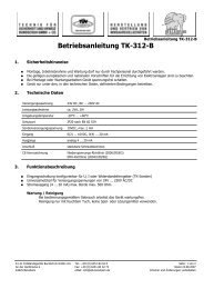
<strong>Uredjaj</strong> <strong>za</strong> <strong>za</strong>štitu <strong>od</strong><br />
<strong>udara</strong> <strong>groma</strong> <strong>BL</strong>-<strong>100</strong><br />
EC Sertifikat <strong>za</strong> Ispitivanje tipa<br />
TÜV <strong>02</strong> <strong>ATEX</strong> <strong>1796</strong> X<br />
Ovaj uredjaj <strong>za</strong> <strong>za</strong>štitu <strong>od</strong> <strong>udara</strong> <strong>groma</strong><br />
obezbedjuje grubu <strong>za</strong>štitu, koja<br />
oganicava prejaku voltažu na<br />
signalnoj liniji prouzorkovanu<br />
atmosferskim uticajima ili ometanjima<br />
elektromasgnetnog polja (udar<br />
<strong>groma</strong>) do <strong>od</strong>redjene vrednosti, tako<br />
da ne može da d<strong>od</strong>je do paljenja usled<br />
lektricnog pražnjenja u eksplozivnoj<br />
atmosferi.<br />
<strong>Uredjaj</strong> <strong>za</strong> <strong>za</strong>štitu <strong>od</strong> <strong>udara</strong> <strong>groma</strong> ne<br />
sadrži <strong>za</strong>štitne komponente koje<br />
o b e z b e d j u j u z a š t i t u o p r e m e<br />
naknadno pove<strong>za</strong>ne.<br />
Prevelika voltaža se prenosi do<br />
potencijalnog konektora <strong>za</strong>štitnicima<br />
Koji rade po principu ispuštanja gasa.<br />
SAFETY AND<br />
ENVIRONMENTAL<br />
TECHNOLOGY<br />
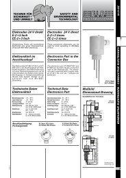
Lightning Protection<br />
Device <strong>BL</strong>-<strong>100</strong><br />
EC Type-Examination Certificate<br />
TÜV <strong>02</strong> <strong>ATEX</strong> <strong>1796</strong> X<br />
This lightning protection device<br />
gives coarse protection, which limits<br />
overvoltages on the signal lines<br />
caused through atmospheric influences<br />
or interference of electromagnetic<br />
fields (lightning strokes) to a certain<br />
value, so that no ignition through<br />
flash-over can occur within the explosive<br />
atmosphere.<br />
The lightning protection device contains<br />
no protective components<br />
giving fine protection of equipment<br />
subsequently connected.<br />
Overvoltages are lead away to the potential<br />
connections by gas dis-charge<br />
protectors.<br />
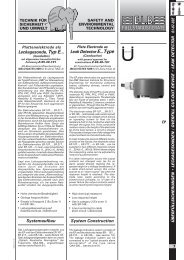
<strong>BL</strong>-<strong>100</strong><br />
01-10-01E<br />
ÜBERFÜLLSICHERUNGEN • LECKAGESONDEN / OVERFILL CUT-OUT DEVICE • LEAK DETECTOR<br />
1
01-10-01E<br />
ÜBERFÜLLSICHERUNGEN • LECKAGESONDEN / OVERFILL CUT-OUT DEVICE • LEAK DETECTOR<br />
2<br />
Tehnicki p<strong>od</strong>aci<br />
Sistem <strong>za</strong>štite EN 60529 IP 65<br />
Materijal kucišta aluminijum<br />
Operativni uslovi u neposrednoj blizini senzora nivoa<br />
(max 3m)<br />
Operativna temperatura -20... +70°C<br />
<strong>Uredjaj</strong> <strong>za</strong> <strong>za</strong>štitu <strong>od</strong> <strong>udara</strong> <strong>groma</strong> <strong>BL</strong>-<strong>100</strong> se koristi<br />
(prema TRBF<strong>100</strong>) kao <strong>za</strong>štitna komponenta protiv<br />
prejake voltaže u instalacijama<br />
Presek veze<br />
Signalne linije Max. 4mm2 proste žice<br />
Max. 2.5mm2 fine žice<br />
Povezivanje mesta sa istim potencijalom<br />
Spolj. Max. 2 x 4 mm2<br />
Min. 4 mm2<br />
Unutr. 2 x max. 4 mm2<br />
Ulaz kabla Metricki M20<br />
Broj jezgara <strong>za</strong> <strong>za</strong>štitu 1, 2 ili 3<br />
Procenjeni minimum operativne direktne voltaže<br />
600V ± 15%<br />
Granicni minimum operativne voltaže<br />
� 1200 V na 1 kV / �s<br />
Kucište <strong>BL</strong>-<strong>100</strong> treba da bude<br />
pouzdano pove<strong>za</strong>no eletricno sa<br />
rezervoarom u svojoj neposrednoj<br />
blizini.<br />
Ve<strong>za</strong> jednakih potencijala preko<br />
spoljašnjih terminala veze <strong>za</strong> <strong>BL</strong>-<strong>100</strong><br />
uz procenjeni presek <strong>od</strong> min. 4 mm².<br />
Signalna linija <strong>od</strong> pojacivaca <strong>za</strong><br />
ukljucivanje van eksplozivne oblasti<br />
do <strong>BL</strong>-<strong>100</strong> uredjaja <strong>za</strong> <strong>za</strong>štitu <strong>od</strong><br />
<strong>udara</strong> <strong>groma</strong> može biti <strong>za</strong>šticena.<br />
Zaštitni oklop treba da bude<br />
pove<strong>za</strong>n <strong>za</strong> mesto jednakih<br />
potencijala (terminal PE 1) samo u<br />
okviru <strong>BL</strong>-<strong>100</strong>. Kabl mora biti<br />
konstruisan prema <strong>za</strong>htevima<br />
dokumenata <strong>za</strong> harmoni<strong>za</strong>ciju 21 i 22<br />
iz CENELECa.<br />
Signalna linija <strong>od</strong> komponente <strong>za</strong><br />
<strong>za</strong>štitu <strong>od</strong> <strong>udara</strong> <strong>groma</strong> do<br />
potencijalno eksplozivne oblasti<br />
treba da bude instalirana sa kablom<br />
dužine max do 3m kao <strong>za</strong>šticenim<br />
kablom ili unutar fleksiblinog<br />
metalnog <strong>za</strong>štitnog ovoja Ili metalne<br />
cevi. Zaštitni, fleksibilni metalni<br />
oklopni ovoj ili metalna cev moraju<br />
biti pouzdano i tacno pove<strong>za</strong>ni<br />
preko veze jednakog potencijala.<br />
Zaštita kabla mora biti pove<strong>za</strong>na<br />
samo sa terminalom (PE 2) unutar<br />
m<strong>od</strong>ula <strong>za</strong> <strong>za</strong>štitu <strong>od</strong> <strong>udara</strong> <strong>groma</strong>.<br />
Za liniju / kabl <strong>od</strong> <strong>BL</strong>-<strong>100</strong> do<br />
rezervoara <strong>za</strong> skladištenje merna<br />
voltaža U izmedju jezgara i metalne<br />
obloge, <strong>za</strong>štite ili fleksibilne metalne<br />
<strong>za</strong>štitne cevi mora biti najmanje<br />
1500V.<br />
Jezgra signalne linije <strong>od</strong> pojacivaca<br />
<strong>za</strong> ukljucivanje moraju biti pove<strong>za</strong>na<br />
sa strane, gde je obeleženo ''ulaz,<br />
ne<strong>za</strong>šticena oblast'' (terminali: IN<br />
1…3).<br />
Jezgra signalne linije koja v<strong>od</strong>e do<br />
senzora nivoa moraju biti pove<strong>za</strong>na<br />
<strong>za</strong> izlaz, Sa strane Ex-zone ( terminali<br />
OUT 1...3).<br />
Zaštite signalnih linija moraju biti<br />
pove<strong>za</strong>ne preko terminala ''PE 1<br />
<strong>za</strong>štita linije do pojacivaca, PE 2 -<br />
<strong>za</strong>štita linije do senzora nivoa''<br />
unutar m<strong>od</strong>ula <strong>za</strong> <strong>za</strong>štitu <strong>od</strong> <strong>udara</strong><br />
<strong>groma</strong>.<br />
Technical Data<br />
System of protection EN 60529 IP 65<br />
Material housing Aluminum<br />
Operating conditions in the immediate vicinity<br />
of the level sensor (max 3 m)<br />
Operating temperature –20...+70 °C<br />
The <strong>BL</strong>-<strong>100</strong> lightning protection device is<br />
used (according to Trbf <strong>100</strong>) as an<br />
overvoltage protective component in installations<br />
Connection cross-sections:<br />
Signal lines max. 4 mm² single wire<br />
max. 2.5 mm² fine wire<br />
Equipotential bonding exterior max. 2 x 4 mm²<br />
min. 4 mm²<br />
interior 2 x max. 4 mm²<br />
Cable inlet<br />
metric M20<br />
Number of cores to be protected<br />
1, 2 or 3<br />
Rated minimum<br />
operating direct voltage<br />
600 V ±15 %<br />
Limiting minimum<br />
operating voltage<br />
� 1200 V at 1kV/�s<br />
Ve<strong>za</strong> Connection<br />
The <strong>BL</strong>-<strong>100</strong> casing should be reliably<br />
connected electrically to the tank in<br />
its immediate vicinity.<br />
The equipotential bonding is connected<br />
via the exterior connection<br />
terminals of the <strong>BL</strong>-<strong>100</strong> with a rated<br />
cross-section of min. 4 mm².<br />
The signal line from the switching<br />
amplifier outside the explosive area<br />
to the <strong>BL</strong>-<strong>100</strong> lightning protection<br />
device can be shielded. The shielding<br />
should be connected to the<br />
equipotential bonding (terminal PE<br />
1) only within the <strong>BL</strong>-<strong>100</strong>. The cable<br />
must be constructed according to<br />
the harmoni<strong>za</strong>tion documents 21<br />
and 22 CENELEC.<br />
The signal line from the lightning<br />
protection component into the potentially<br />
explosive area should be installed<br />
with a cable length of max. 3<br />
m as a shielded cable or inside flexible<br />
metallic protective tubing or a<br />
metal tube. The shielding, flexible<br />
metallic protective tubing or metal<br />
tube must be reliably connected to<br />
the equipotential bonding. Cable<br />
shielding must be connected only to<br />
the terminal (PE 2) inside the lightning<br />
protection m<strong>od</strong>ule.<br />
For the line / cable from the <strong>BL</strong>-<strong>100</strong> to<br />
the storage tank the testing voltage<br />
Ueff between the cores and the me-<br />
tallic sheath, shielding or flexible metallic<br />
protective tubing must be at<br />
least 1500V eff .<br />
The cores of the signal line coming<br />
from the switching amplifier must<br />
be connected to the side marked “input,<br />
unprotected area” (terminals: IN<br />
1…3).<br />
The cores of the signal line leading to<br />
the level sensor must be connected<br />
to the output, Ex-zone side (terminals<br />
OUT 1…3).<br />
Shielding of the signal lines must be<br />
connected to the terminals “PE 1 –<br />
shielding of line to switching amplifier,<br />
PE 2 – shielding of line to level<br />
sensor” inside the lightning protection<br />
m<strong>od</strong>ule.<br />
KOLTEX D.O.O.<br />
Kralja Milana 21<br />
1 1 0 0 0 B e o g r a d<br />
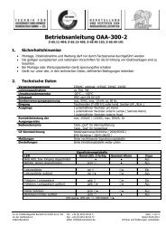
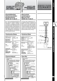
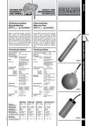
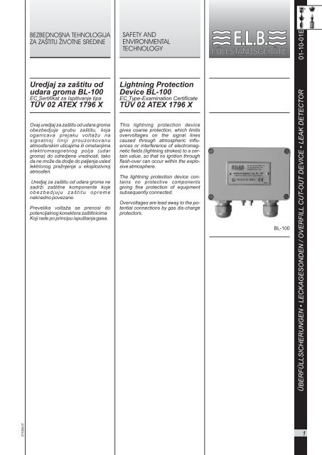
Dimenzioni crtez<br />
Dimensional Drawing<br />
M 20 x 1.5<br />
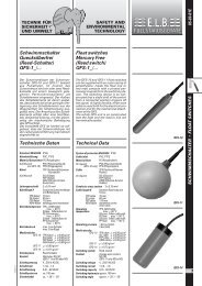
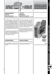
IN1<br />
IN2<br />
IN3<br />
PE1<br />
37,5 37,5<br />
Svi otvori i navoji na zidu<br />
All threads and boreholes in wall A<br />
Dimenzije u mm / Dimensioning in mm<br />
IN1<br />
Pas0<br />
IN2<br />
Pas0<br />
IN3<br />
Pas0<br />
PE1<br />
Pas0<br />
Pas1 Pas1<br />
USS1<br />
PE<br />
Pas0<br />
Kuciste / Housing<br />
Pas1 Pas1<br />
USS2<br />
125<br />
Moguce izmene bez preth<strong>od</strong>ne najave.<br />
Subject to change without prior notice,<br />
errors excepted.<br />
Z<br />
Pas1 Pas1<br />
USS3<br />
OUT1<br />
PE2<br />
OUT2<br />
OUT3<br />
Sema ve<strong>za</strong> <strong>BL</strong>-<strong>100</strong> / Circuit diagram <strong>BL</strong>-<strong>100</strong><br />
57 80<br />
OUT1<br />
Pas0<br />
OUT2<br />
Pas0<br />
OUT3<br />
Pas0<br />
PE2<br />
Pas0<br />
Telefon+<br />
381 ( 0)11/3232-687<br />
Fax + 381 ( 0)11/3343-740<br />
E-Mail: Koltexdoo@ptt.yu<br />
Info: Www.elb-bensheim.de<br />
27<strong>100</strong>4.08