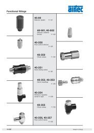
Pneumatic cylinders, piston-Ã 32 â 100 mm Double acting with ...
Pneumatic cylinders, piston-Ã 32 â 100 mm Double acting with ...
Pneumatic cylinders, piston-Ã 32 â 100 mm Double acting with ...
- No tags were found...

Create successful ePaper yourself
Turn your PDF publications into a flip-book with our unique Google optimized e-Paper software.
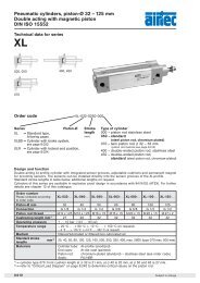
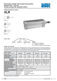
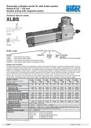
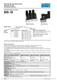
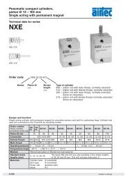
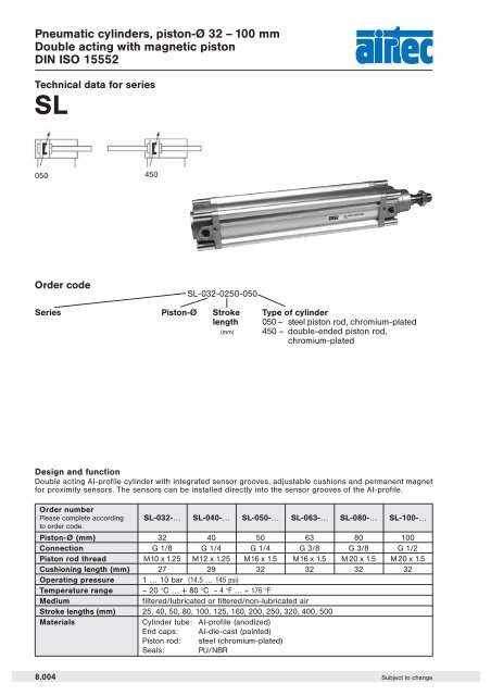
<strong>Pneumatic</strong> <strong>cylinders</strong>, <strong>piston</strong>-Ø <strong>32</strong> – <strong>100</strong> <strong>mm</strong><strong>Double</strong> <strong>acting</strong> <strong>with</strong> magnetic <strong>piston</strong>DIN ISO 15552Technical data for seriesSL050 450Order codeSL-0<strong>32</strong>-0250-050Series Piston-Ø Strokelength(<strong>mm</strong>)Type of cylinder050 – steel <strong>piston</strong> rod, chromium-plated450 – double-ended <strong>piston</strong> rod,chromium-platedDesign and function<strong>Double</strong> <strong>acting</strong> Al-profile cylinder <strong>with</strong> integrated sensor grooves, adjustable cushions and permanent magnetfor proximity sensors. The sensors can be installed directly into the sensor grooves of the Al-profile.Order numberPlease complete accordingto order code.Piston-Ø (<strong>mm</strong>)SL-0<strong>32</strong>-…<strong>32</strong>SL-040-…40SL-050-…50SL-063-…63SL-080-…80SL-<strong>100</strong>-…<strong>100</strong>Connection G 1/8 G 1/4 G 1/4 G 3/8 G 3/8 G 1/2Piston rod thread M10x1.25 M12x1.25 M16x1.5 M16x1.5 M20x1.5 M20x1.5Cushioning length (<strong>mm</strong>) 27 29 <strong>32</strong> <strong>32</strong> <strong>32</strong> <strong>32</strong>Operating pressure 1 … 10 bar (14.5 … 145 psi)Temperature range – 20 °C … + 80 °C – 4 °F … + 176 °FMediumfiltered/lubricated or filtered/non-lubricated airStroke lengths (<strong>mm</strong>) 25, 40, 50, 80, <strong>100</strong>, 125, 160, 200, 250, <strong>32</strong>0, 400, 500Materials Cylinder tube: Al-profile (anodized)End caps: Al-die-cast (painted)Piston rod: steel (chromium-plated)Seals: PU/NBR8.004 Subject to change
<strong>Pneumatic</strong> <strong>cylinders</strong>, <strong>piston</strong>-Ø <strong>32</strong> – <strong>100</strong> <strong>mm</strong><strong>Double</strong> <strong>acting</strong> <strong>with</strong> magnetic <strong>piston</strong>DIN ISO 15552Technical data for seriesSLForce chart for series SLPiston-Ø (<strong>mm</strong>) Extension Retraction<strong>32</strong> 430 N (96.6 lbf.) 370 N (83.2 lbf.)40 680 N (152.8 lbf.) 570 N (128.1 lbf.)50 1060 N (238.3 lbf.) 890 N (200.1 lbf.)63 1680 N (377.7 lbf.) 1510 N (339.5 lbf.)80 2700 N (607.0 lbf.) 2550 N (573.3 lbf.)<strong>100</strong> 4240 N (953.2 lbf.) 3970 N (892.5 lbf.)Pressure 6 bar. The internal friction is considered.Permissible side load for series SL (N)Distance A (<strong>mm</strong>)Piston-Ø25 40 50 80 <strong>100</strong> 125 160 200 250 <strong>32</strong>0 400 500<strong>32</strong> 75 55 50 40 34 28 23 20 16 12 9 740 175 150 130 105 91 78 62 55 45 35 28 2150 + 63 220 180 170 130 120 105 90 80 65 52 43 3380 + <strong>100</strong> 500 450 400 350 310 270 230 205 180 150 125 <strong>100</strong>Subject to change8.005
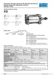
<strong>Pneumatic</strong> <strong>cylinders</strong>, <strong>piston</strong>-Ø <strong>32</strong> – <strong>100</strong> <strong>mm</strong><strong>Double</strong> <strong>acting</strong> <strong>with</strong> magnetic <strong>piston</strong>DIN ISO 15552Dimensions for seriesSL (Type for order code: –050)view AAnPiston-Ø BAØØ BABG Ø D2 E EE J4 KK L2 L3 L7<strong>32</strong> 22 30 16.5 12 44 G 1/8 3.5 M 10 x 1.25 18 5 11.540 24 35 16.5 16 51 G 1/4 7.5 M 12 x 1.25 22 5 12.550 <strong>32</strong> 40 16.5 20 59.5 G 1/4 5 M 16 x 1.5 25.5 4.5 13.2563 <strong>32</strong> 45 16.5 20 69.5 G 3/8 16 M 16 x 1.5 25 4.5 880 40 45 17 25 87 G 3/8 20.5 M 20 x 1.5 35 – 9.25<strong>100</strong> 40 55 17 25 106.5 G 1/2 21.5 M 20 x 1.5 38 – 8-2 d11 f 7Piston-ØL8 PL PV RT SW SW1 SW2 SW3 TG VA VD WH<strong>32</strong> 94 12.5 – M6 10 17 6 2 <strong>32</strong>.5 4 8 2640 105 14 – M6 13 19 6 2.5 38 4 12 3050 106 14 – M8 17 24 8 2.5 46.5 4 10.5 3763 121 20 7 M8 17 24 8 2.5 56.5 4 8.5 3780 128 18.5 6.5 M10 22 30 6 4 72 4 10 46<strong>100</strong> 138 20 12 M10 22 30 6 4 89 4 12.5 51Piston-Ø <strong>32</strong> 40 50 63 80 <strong>100</strong>Mass at 0 <strong>mm</strong> stroke in kg 0.582 0.861 1.289 1.723 2.873 3.879add-on per <strong>100</strong> <strong>mm</strong> stroke 0.208 0.308 0.400 0.421 0.613 0.6828.006 Subject to change
<strong>Pneumatic</strong> <strong>cylinders</strong>, <strong>piston</strong>-Ø <strong>32</strong> – <strong>100</strong> <strong>mm</strong><strong>Double</strong> <strong>acting</strong> <strong>with</strong> magnetic <strong>piston</strong>DIN ISO 15552Dimensions for seriesSL (Type for order code: –450)view AAnPiston-ØA Ø B BG Ø D2 E EE J4 KK L2 L3 L7<strong>32</strong> 22 30 16.5 12 44 G 1/8 3.5 M 10 x 1.25 18 5 11.540 24 35 16.5 16 51 G 1/4 7.5 M 12 x 1.25 22 5 12.550 <strong>32</strong> 40 16.5 20 59.5 G 1/4 5 M 16 x 1.5 25.5 4.5 13.2563 <strong>32</strong> 45 16.5 20 69.5 G 3/8 16 M 16 x 1.5 25 4.5 880 40 45 17 25 87 G 3/8 20.5 M 20 x 1.5 35 – 9.25<strong>100</strong> 40 55 17 25 106.5 G 1/2 21.5 M 20 x 1.5 38 – 8-2 d11 f 7Piston-ØL8 PM PV RT SW SW1 SW2 SW3 TG VD WH ZM<strong>32</strong> 94 12.5 – M6 10 17 6 2 <strong>32</strong>.5 8 26 14640 105 14 – M6 13 19 6 2.5 38 12 30 16550 106 14 – M8 17 24 8 2.5 46.5 10.5 37 18063 121 20 7 M8 17 24 8 2.5 56.5 8.5 37 19580 128 18.5 6.5 M10 22 30 6 4 72 10 46 220<strong>100</strong> 138 20 12 M10 22 30 6 4 89 12.5 51 240Piston-Ø <strong>32</strong> 40 50 63 80 <strong>100</strong>Mass at 0 <strong>mm</strong> stroke in kg 0.654 0.996 1.536 1.996 3.348 4.438add-on per <strong>100</strong> <strong>mm</strong> stroke 0.296 0.465 0.645 0.666 0.995 1.064Subject to change8.007
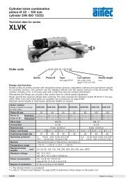
Accessories for pneumatic <strong>cylinders</strong>series SLDIN ISO 15552Accessories for seriesSLPiston rod accessoriesFlexible couplingFKPage 8.035 and 8.213Rod eyeFO + ROPage 8.035 and 8.213Rod clevis <strong>with</strong> pinFD + RDPage 8.035 and 8.212Piston rod nutFE + RLPage 8.035 and 8.212Mounting accessoriesFoot mountXLB-Ø-01Page 8.016Flange mountXLB-Ø-02Page 8.016Clevis mount <strong>with</strong> bushingXLB-Ø-04Page 8.017Swivel mountXLB-Ø-05Page 8.018Swivel mount 90hXLB-Ø-06Page 8.018Swivel mount <strong>with</strong>spherical bearingXLB-Ø-12Page 8.019Trunnion flange mountXLB-Ø-11Page 8.021Small clevis mount<strong>with</strong> non rotating pinXLB-Ø-14Page 8.021Clevis pinXLB-Ø-08Page 8.019Bearing blockXLB-Ø-09Page 8.020Linear guidesLE-Page 8.200Proximity sensorsSensorsZS-Page 8.220Connecting cableKA-Page 8.221Cover for sensor grooveXLB-011 0.5 m8.008 Subject to change
Accessories for pneumatic <strong>cylinders</strong>series SLAllocationSeries Cylinders Ø Screw thread Rod clevis Piston rod nutFlexiblecouplingRod eyeSL Ø <strong>32</strong> M 10 x 1.25 RD-25 RL-25 FK-<strong>32</strong> RO-25SL Ø 40 M 12 x 1.25 FD-40 FE-40 FK-40 FO-40SL Ø 50 and 63 M 16 x 1.5 FD-63 FE-63 FK-63 FO-63SL Ø 80 and <strong>100</strong> M 20 x 1.5 FD-80 FE-80 FK-80 FO-80Rod clevis <strong>with</strong> pinOrder number A B C D E F G HRD-25 M 10 x 1.25 20 40 26 10 52 20 10FD-40 M 12 x 1.25 24 48 <strong>32</strong> 12 62 24 12FD-63 M 16 x 1.5 <strong>32</strong> 64 40 16 83 <strong>32</strong> 16FD-80 M 20 x 1.5 40 80 50 20 105 40 20Material:steel (zincplated)stainless steelPiston rod nutOrder number A B CRL-25 M 10 x 1.25 6 17FE-40 M 12 x 1.25 7 19FE-63 M 16 x 1.5 8 24FE-80 M 20 x 1.5 9 30Material: steel (zinc-plated)Flexible couplingMaterial: steel (zinc-plated)Order number A B C D E F G K L M N O PFK-<strong>32</strong> M 10 x 1.25 SW 17 SW 12 14 35 SW 19 22 71 20 5 20 30 <strong>32</strong>FK-40 M 12 x 1.25 SW 19 SW 12 14 35 SW 19 22 75 24 5 20 30 <strong>32</strong>FK-63 M 16 x 1.5 SW 24 SW 20 22 54 SW 30 <strong>32</strong> 103 <strong>32</strong> 8 <strong>32</strong> 41 45FK-80 M 20 x 1.5 SW 30 SW 20 22 54 SW 30 <strong>32</strong> 119 40 8 40 41 45Rod eyeMaterial: steel (zinc-plated)stainless steelOrder number d 3 d d 1 d 2 d 4 d 5 B C 1 W L 3 L 4 h 1 “RO-25 M10x1.25 10 12.9 28 15 19 14 10.5 17 20 57 43 13FO-40 M 12 x 1.25 12 15.4 <strong>32</strong> 17.5 22 16 12 19 22 66 50 13FO-63 M16x1.5 16 19.3 42 22 27 21 15 22 28 85 64 15FO-80 M 20 x 1.5 20 24.3 50 27.5 34 25 18 <strong>32</strong> 33 102 77 15Änderungen vorbehalten8.009
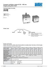
Accessories for <strong>cylinders</strong>series XLMounting accessories for seriesXLFoot mount1 pairDIN EN ISO4762Material: steel (zinc-plated)Order number Ø AB AH AO AU AT E L7 R2 S TG TG2 TRXLB-0<strong>32</strong>-01 7 <strong>32</strong> 11 24 4 45 30 15 M 6 x 20 <strong>32</strong>.5 16.25 <strong>32</strong>XLB-040-01 10 36 8 28 4 52 30 17.5 M 6 x 20 38 19 36XLB-050-01 10 45 15 <strong>32</strong> 5 65 36 20 M 8 x 20 46.5 23.25 45XLB-063-01 10 50 13 <strong>32</strong> 5 75 35 22.5 M 8 x 20 56.5 28.25 50XLB-080-01 12 63 14 41 6 95 47 22.5 M 10 x 20 72 36 63XLB-<strong>100</strong>-01 14.5 71 16 41 6 115 53 27.5 M 10 x 20 89 44.5 75XLB-125-01 16.5 90 25 45 8 140 70 30 M 12 x 25 110* 55 90H14 JS16 ± 0.2 H15± 0.2*± 0.3JS14Flange mountDIN 7984Material: steel (zinc-plated)Order number Ø D E Ø FB L4 MF R S TF TG UFXLB-0<strong>32</strong>-02 30 45 7 5 10 <strong>32</strong> M 6 x 20 64 <strong>32</strong>.5 80XLB-040-02 35 52 9 5 10 36 M 6 x 20 72 38 90XLB-050-02 40 65 9 6.5 12 45 M 8 x 20 90 46.5 110XLB-063-02 45 75 9 6.5 12 50 M 8 x 20 <strong>100</strong> 56.5 120XLB-080-02 45 95 12 9 16 63 M 10 x 25 126 72 150XLB-<strong>100</strong>-02 55 115 14 9 16 75 M 10 x 25 150 89 170XLB-125-02 60 140 16 10.5 20 90 M 12 x 25 180 110* 205H11 H13 – 0.5 JS14 JS14 JS14± 0.2*± 0.38.016 Subject to change
Accessories for <strong>cylinders</strong>series XLMounting accessories for seriesXLClevis mount<strong>with</strong> bushingDIN EN ISO 4762Material: AlBestell-Nr. CB Ø CD Ø D E FL L L1 L4 MR S TG UBXLB-0<strong>32</strong>-04 26 10 30 45 22 13 5 5.5 10 M 6 x 20 <strong>32</strong>.5 45XLB-040-04 28 12 35 52 25 16 5 5.5 12 M 6 x 20 38 52XLB-050-04 <strong>32</strong> 12 40 65 27 16 5 6.5 12 M 8 x 20 46.5 60XLB-063-04 40 16 45 75 <strong>32</strong> 21 5 6.5 16 M 8 x 20 56.5 70XLB-080-04 50 16 45 95 36 22 5 10 16 M 10 x 25 72 90XLB-<strong>100</strong>-04 60 20 55 115 41 27 5 10 20 M 10 x 25 89 110XLB-125-04 70 25 60 140 50 30 7 10 25 M 12 x 25 110* 130H14 H9 H11 ± 0.2 ± 0.5± 0.2*± 0.3h138Subject to change8.017
Accessories for <strong>cylinders</strong>series XLMounting accessories for seriesXLSwivel mountDIN EN ISO 4762Material: AlOrder number Ø CD Ø D E EW FL L L1 L4 MR S TGXLB-0<strong>32</strong>-05 10 30 45 26 22 13 5 5.5 10 M 6 x 20 <strong>32</strong>.5XLB-040-05 12 35 52 28 25 16 5 5.5 12 M 6 x 20 38XLB-050-05 12 40 65 <strong>32</strong> 27 16 5 6.5 12 M 8 x 20 46.5XLB-063-05 16 45 75 40 <strong>32</strong> 21 5 6.5 16 M 8 x 20 56.5XLB-080-05 16 45 95 50 36 22 5 10 16 M 10 x 25 72XLB-<strong>100</strong>-05 20 55 115 60 41 27 5 10 20 M 10 x 25 89XLB-125-05 25 60 140 70 50 30 7 10 25 M 12 x 25 110*H9 H11 ± 0.2 ± 0.5± 0.2*± 0.3Swivel mount 90°Material: AlOrder number BR BT Ø CK Ø D EA EM GL Ø HB L2 LD PH RA TE UL URXLB-0<strong>32</strong>-06 10 8 10 21 10 26 21 6.6 1.6 3 <strong>32</strong> 18 38 51 31XLB-040-06 11 10 12 21 15 28 24 6.6 1.6 3 36 22 41 54 35XLB-050-06 13 12 12 21 16 <strong>32</strong> 33 9 1.6 3 45 30 50 65 45XLB-063-06 15 14 16 21 16 40 37 9 1.6 3 50 35 52 67 50XLB-080-06 15 14 16 21 20 50 47 11 2.5 3 63 40 66 86 60XLB-<strong>100</strong>-06 19 17 20 11 20 60 55 11 2.5 3 71 50 76 96 70XLB-125-06 22.5 20 25 21 30 70 70 14 3.2 3 90 60 94 124 90H9 JS14 H13 JS15 JS14 JS148.018 Subject to change
Accessories for <strong>cylinders</strong>series XLMounting accessories for seriesXLSwivel mount<strong>with</strong> sphericalbearingMaterial: AlOrder number Ø CX Ø D DL E EP EX L L1 L3 L4 MS R1 S TGXLB-0<strong>32</strong>-12 10 30 22 45 10.5 14 12 7 – 5.5 16 – M 6 x 20 <strong>32</strong>.5XLB-040-12 12 35 25 52 12 16 15 7 – 5.5 18 – M 6 x 20 38XLB-050-12 16 40 27 65 15 21 15 7 51 6.5 21 19 M 8 x 20 46.5XLB-063-12 16 45 <strong>32</strong> 75 15 21 20 7 – 6.5 23 – M 8 x 20 56.5XLB-080-12 20 45 36 95 18 25 20 9 74 10 28 24 M 10 x 25 72XLB-<strong>100</strong>-12 20 55 41 115 18 25 25 9 – 10 30 – M 10 x 25 89XLB-125-12 30 60 50 140 25 37 30 9 – 10 40 – M 12 x 25 110*H7 H11 ± 0.2 ± 0.1 ± 0.5± 0.2*± 0.3Clevis pin8Material: steel (zinc-plated)Snap rings are included.Order number A Ø B Ø EK EL LBXLB-0<strong>32</strong>-08 53 9.6 10 46 1.1XLB-040-08 60 11.5 12 53 1.1XLB-050-08 68 11.5 12 61 1.1XLB-063-08 78 15.2 16 71 1.1XLB-080-08 98 15.2 16 91 1.1XLB-<strong>100</strong>-08 118 19 20 111 1.3XLB-125-08 139 23.9 25 1<strong>32</strong>* 1.3e8+ 2*+ 3Subject to change8.019
Accessories for <strong>cylinders</strong>series XLMounting accessories for seriesXLBearing block(1 pair)Order number = 1 pairMaterial: steel (zinc-plated), bronzeOrder number Ø A Ø B C Ø CR FK FN Ø HB LA NH TH ULXLB-0<strong>32</strong>-09 11 22 10.5 12 15 30 6.6 7 18 <strong>32</strong> 46XLB-040-09 15 28 12 16 18 36 9 9 21 36 55XLB-063-09 18 <strong>32</strong> 13 20 20 40 11 11 23 42 65XLB-<strong>100</strong>-09 20 39 16 25 25 50 14 13 28.5 50 75H9 ± 0.1 H13 ± 0.2Trunnion mountMounting positionarbitrary.Material: steel (zinc-plated)Order numberSW1 SW2DIN 914 DIN 7984Ø TD TK TL TM UWXLB-0<strong>32</strong>-10 3 2.5 12 25 12 50 65XLB-040-10 3 3 16 25 16 63 75XLB-050-10 3 4 16 30 16 75 95XLB-063-10 3 4 20 30 20 90 105XLB-080-10 3 4 20 30 20 110 130XLB-<strong>100</strong>-10 4 5 25 40 25 1<strong>32</strong> 145XLB-125-10 4 6 25 40 25 160 175DIN EN ISO 4762 e 9 h14 h148.020 Subject to change
Accessories for <strong>cylinders</strong>series XLMounting accessories for seriesXLTrunnion flange mountMaterial: steel (zinc-plated)Order number D L L4 S TD TG TK TL Ø TM USXLB-0<strong>32</strong>-11 30 6.5 8 M 6 x 20 12 <strong>32</strong>.5 14 12 50 46XLB-040-11 35 9 13 M 6 x 25 16 38 19 16 63 59XLB-050-11 40 9 11 M 8 x 25 16 46.5 19 16 75 69XLB-063-11 45 11.5 16 M 8 x 30 20 56.5 24 20 90 84XLB-080-11 45 11.5 14 M 10 x 30 20 72 24 20 110 102XLB-<strong>100</strong>-11 55 14 19 M 10 x 35 25 89 29 25 1<strong>32</strong> 125H11 + 0.2 e9 ± 0.2 h14 h14Small clevis mount <strong>with</strong> non rotating pin8Material of clevis: Alof pin: steel (zinc-plated)Order number CF CG CP D E FM L1 L4 L10 R4 S SR TGXLB-0<strong>32</strong>-14 10 14 34 30 45 22 5 5.5 9 17 M 6 x 20 10 <strong>32</strong>.5XLB-040-14 12 16 40 35 52 25 5 5.5 9 20 M 6 x 20 12 38XLB-050-14 16 21 45 40 65 27 5 6.5 11 22 M 8 x 20 14 46.5XLB-063-14 16 21 51 45 75 <strong>32</strong> 5 6.5 11 25 M 8 x 20 18 56.5XLB-080-14 20 25 65 45 95 36 5 10 14 30 M 10 x 25 20 72XLB-<strong>100</strong>-14 20 25 75 55 115 41 5 10 14 <strong>32</strong> M 10 x 25 22 89XLB-125-14 30 37 97 60 140 50 7 10 20 42 M 12 x 25 25 110*F7 D10 d 12 H11 ± 0.2 ± 0.5± 0.2*± 0.3Subject to change8.021
Piston rod accessoriesAssignment to seriesSeries Cylinder Ø Piston rodPiston rod FlexibleRod clevis<strong>mm</strong> thread nut couplingRod eyeHM Ø 8 and 10 M 4 RD-10 RL-10 – –NXD Ø 12HM Ø 12 and 16M 6 RD-16 RL-16 FK-16 RO-16NXD Ø 16HM Ø 20 M 8 RD-20 RL-20 FK-20 RO-20XV Ø 20 and 25NXD Ø 20 to 40HM Ø 25 M 10 x 1,25 RD-25 RL-25 FK-<strong>32</strong> RO-25XL Ø <strong>32</strong>XV Ø <strong>32</strong> and 40HM Ø <strong>32</strong> M 10 RD-<strong>32</strong> RL-<strong>32</strong> FK-33 RO-<strong>32</strong>HM Ø 40 M 12 RD-40 RL-40 FK-41 RO-40HM Ø 50 and 63 M 16 RD-63 RL-63 – RO-50NXD Ø 50 and 63XL Ø 40M 12 x 1,25 FD-40 FE-40 FK-40 FO-40XV Ø 50 and 63NXD Ø 80XL Ø 50 and 63M 16 x 1,5 FD-63 FE-63 FK-63 FO-63NXD Ø <strong>100</strong>XL Ø 80 and <strong>100</strong>M 20 x 1,5 FD-80 FE-80 FK-80 FO-80XV Ø 80 and <strong>100</strong>XL Ø 125 M 27 x 2 FD-125 FE-125 FK-125 FO-125XG Ø 160 and 200 M 36 x 2 FD-200 FE-200 – FO-200Rod clevis <strong>with</strong> pinOrder number A B C D E F G HRD-10 M4 8 16 11,5 4 21 8 4RD-16 M 6 12 24 16 6 31 12 6RD-20 M 8 16 <strong>32</strong> 22 8 42 16 8RD-25 M 10 x 1,25 20 40 26 10 52 20 10RD-<strong>32</strong> M10 20 40 26 10 52 20 10RD-40 M12 24 48 <strong>32</strong> 12 62 24 12RD-63 M16 <strong>32</strong> 64 36 16 83 <strong>32</strong> 16FD-40 M 12 x 1,25 24 48 <strong>32</strong> 12 62 24 12FD-63 M 16 x 1,5 <strong>32</strong> 64 40 16 83 <strong>32</strong> 16FD-80 M 20 x 1,5 40 80 50 20 105 40 20FD-125 M 27 x 2 54 110 65 30 148 55 30FD-200 M36 x 2 72 144 84 35 188 70 35Material: steel (zinc-plated)spring steelPiston rod nutOrder number A B CRL-10 M4 3,2 7RL-16 M6 5 10RL-20 M8 6,5 13RL-25 M 10 x 1,25 6 17RL-<strong>32</strong> M10 6 17RL-40 M12 7 19RL-63 M16 8 24FE-40 M 12 x 1,25 7 19FE-63 M 16 x 1,5 8 24FE-80 M 20 x 1,5 9 30FE-125 M 27 x 2 12 41FE-200 M36 x 2 14 55Rod clevis FD-125 and FD-200, pin <strong>with</strong> snap rings.Material: steel (zinc-plated)8.212 Subject to change
Piston rod accessoriesFlexible couplingview AMaterial: steel (zinc-plated)OrdernumberA B C D E F G K L M N O PFK-16 M 6 SW 10 SW 5 6 17.5 SW 7 8.5 35 10 3.5 10 13 15FK-20 M 8 SW 13 SW 7 8 28.5 SW 11 12.5 57 20 4 20 17 19FK-<strong>32</strong> M 10 x 1.25 SW 17 SW 12 14 35 SW 19 22 71 20 5 20 30 <strong>32</strong>FK-33 M10 SW17 SW12 14 35 SW19 22 71 20 5 20 30 <strong>32</strong>FK-40 M 12 x 1.25 SW 19 SW 12 14 35 SW 19 22 75 24 5 20 30 <strong>32</strong>FK-41 M12 SW19 SW12 14 35 SW19 22 75 24 5 20 30 <strong>32</strong>FK-63 M 16 x 1.5 SW 24 SW 20 22 54 SW 30 <strong>32</strong> 103 <strong>32</strong> 8 <strong>32</strong> 41 45FK-80 M 20 x 1.5 SW 30 SW 20 22 54 SW 30 <strong>32</strong> 119 40 8 40 41 45FK-125 M 27 x 2 SW 46 SW 24 <strong>32</strong>.2 60 SW 54 57 147 49.5 9.5 40 65 70Rod eye8Material: steel (zinc-plated)stainless steelOrdernumberd 3 d d 1 d 2 d 4 d 5 B C 1 W L 3 L 4 h 1 “RO-16 M 6 6 8.9 20 10 13 9 6.75 11 12 40 30 13RO-20 M 8 8 10.4 24 12.5 16 12 9 13 16 48 36 13RO-25 M 10 x 1.25 10 12.9 28 15 19 14 10.5 17 20 57 43 13RO-<strong>32</strong> M10 10 12.9 28 15 19 14 10.5 17 20 57 43 13RO-40 M12 12 15.4 <strong>32</strong> 17.5 22 16 12 19 22 66 50 13RO-50 M16 16 19.3 42 22 27 21 15 22 28 85 64 15FO-40 M 12 x 1.25 12 15.4 <strong>32</strong> 17.5 22 16 12 19 22 66 50 13FO-63 M16x1.5 16 19.3 42 22 27 21 15 22 28 85 64 15FO-80 M 20 x 1.5 20 24.3 50 27.5 34 25 18 <strong>32</strong> 33 102 77 15FO-125 M27x2 30 34.8 70 40 51 37 25 41 51 145 110 15FO-200 M36x2 35 37.7 80 46 56 43 28 50 56 165 125 15Subject to change8.213
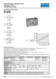
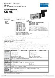
Proximity sensorsWiring diagramDimensionsZS-5200ZS-5201ZS-5200, ZS-5300,ZS-5300-05,ZS-6300, ZS-7300ZS-5300, ZS-5300-05ZS-5301ZS-6300, ZS-7300ZS-6301, ZS-7301ZS-5201, ZS-5301,ZS-6301, ZS-7301413Function principlesMagnetic field sensors are actuated by magnetic fields and are especially suited for <strong>piston</strong> position detection inpneumatic <strong>cylinders</strong>. Based on the fact that magnetic fields can permeate non-magnetizable metals, it is possibleto detect a permanent magnet attached to the <strong>piston</strong> through the aluminum wall of the cylinder.Mounting tipThe sensor is firmly fixed in the groove by clockwise rotation of the screw.Order number ZS-5200 ZS-5201 ZS-5300 ZS-5300-05 ZS-5301Design 2-pole Reed sensor 3-pole Reed sensor*(non-polarized) normally opennormally openCable l 3, Lif9Y-11Y, PUR l 3, LifYY-11Y, PURCable cross section 2 x 0.14 <strong>mm</strong> 2 3 x 0.14 <strong>mm</strong> 2Cable length 3 m 0,3 m 3 m 5 m 0,3 mCable plug – M8 – – M8Overtravel speed≤ 10 m/sMax. absolute hysteresis≤ 1 <strong>mm</strong>Temperature drift≤ 0.1 <strong>mm</strong>Min. absolute repeat accuracy≤ ± 0.1 <strong>mm</strong>Operating temperature – 25 °C … + 70 °CDegree of protection IP 67Housing material Plastic PA 12Switching status indicationLED yellowRated operational voltage 3 … 140 VAC / 4 … 200 VDC 10 … 30 V DC*Rated operational DC ≤ <strong>100</strong> mA ≤ 500 mAcurrent I E AC ≤ <strong>100</strong> mA ≤ 500 mABreaking capacity10 WNo-load current0 mAMax. OFF-state current0 mAMax. switching frequency≤ 0.5 kHzRated insulation voltage≤ 0.5 kVShort-circuit protectionnoMax. voltage drop at I E ≤ 3 V ≤ 0.5 VWire breakagenoReverse polarity protectionyesVibration resistance55 Hz (1 <strong>mm</strong>)Shock resistance30 g (11 ms)Explosion proof –* Useable as 2-wire contact, voltage 0 … 30 V AC / 0 … 30 V DC, LED has no function.8.220 Subject to change
Proximity sensorsMounting bracket for round cylinder Ø 8 – 63 <strong>mm</strong>Material: PA,steel zinc platedOrder numberNT-0810NT-1216NT-2025NT-00<strong>32</strong>NT-0040NT-0050NT-0063Piston-Ø8 and 10 <strong>mm</strong>12 and 16 <strong>mm</strong>(Series XG Ø 160 and 200 <strong>mm</strong>)20 and 25 <strong>mm</strong>(Series XG Ø 250 and <strong>32</strong>0 <strong>mm</strong>)<strong>32</strong> <strong>mm</strong>40 <strong>mm</strong>50 <strong>mm</strong>63 <strong>mm</strong>Material: metal,plastic PA GI/6TOrder numberNT-0825NT-<strong>32</strong>63Piston-Ø8 – 25 <strong>mm</strong><strong>32</strong> – 63 <strong>mm</strong>Connecting cable for ZS-5201, ZS-5301, ZS-6301 and ZS-7301BU 34 BK1 BNCable: PUR, black, 3 x 0,25 <strong>mm</strong> 2 , l 3.9, high flexibleOperating voltage 0 … 48 V AC/DCOrder number Length of cable ConnectionKA-30 3 m 8 <strong>mm</strong> sensor snap-in, straightKA-50 5 m 8 <strong>mm</strong> sensor snap-in, straightKA-51 5 m 8 <strong>mm</strong> sensor snap-in, 90°KA-<strong>100</strong> 10 m 8 <strong>mm</strong> sensor snap-in, straightKA-101 10 m 8 <strong>mm</strong> sensor snap-in, 90°Proximity sensors electronicOrder number ZS-6300 ZS-6301 ZS-7300 ZS-7301Designelectronic, magnet-induktive sensor,normally open PNP outputCablel 3, LifYY-11Y, PURCable cross section 3 x 0.14 <strong>mm</strong> 2Cable lengths 3 m 0.3 m 3 m 0.3 mCable plug – M8 – M8Overtravel speed≤ 10 m/sMax. absolute hysteresis≤ 1 <strong>mm</strong>Temperature drift≤ 0.1 <strong>mm</strong>Min. absolute repeat accuracy≤ ± 0.1 <strong>mm</strong>Operating temperature – 25 °C … + 70 °CDegree of protection IP 67Housing material Plastic, PA 12Switching status indicationLED yellowRated operational voltage10 … 30 V DC, max. ripple ≤ 10 % UppRated operational DC ≤ 200 mAcurrent I E AC –Breaking capacity6 WNo-load current≤ 15 mAMax. OFF-state current≤ 0.1 mAMax. switching frequency≤ 1 kHzRated insulation voltage≤ 0.5 kVShort-circuit protectionyes, cyclicMax. voltage drop at I E≤ 1.8 VWire breakageyesReverse polarity protectionyes /completeVibration resistance55 Hz (1 <strong>mm</strong>)Shock resistance30 g (11 ms)Explosion proof – II 3 GD EEx nA II T4 X IP 67 T 110 °C8Subject to change8.221