Pneumatic cylinder with locked end position Piston-Ã 63 â 125 mm ...
Pneumatic cylinder with locked end position Piston-Ã 63 â 125 mm ...
Pneumatic cylinder with locked end position Piston-Ã 63 â 125 mm ...

Create successful ePaper yourself
Turn your PDF publications into a flip-book with our unique Google optimized e-Paper software.
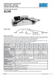
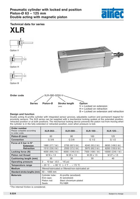
<strong>Pneumatic</strong> <strong>cylinder</strong> <strong>with</strong> <strong>locked</strong> <strong>end</strong> <strong>position</strong><strong>Piston</strong>-Ø <strong>63</strong> – <strong>125</strong> <strong>mm</strong>Double acting <strong>with</strong> magnetic pistonTechnical data for seriesXLROption VOption HOption BOrder codeXLR-080-0250-VOrder numberPlease complete according XLR-0<strong>63</strong>-… XLR-080-… XLR-100-… XLR-<strong>125</strong>-…to order code.<strong>Piston</strong>-Ø (<strong>mm</strong>) <strong>63</strong> 80 100 <strong>125</strong>Connection G 3/8 G 3/8 G 1/2 G 1/2Force at 6 bar in N*Extension 1680 (377.7 lbf.) 2700 (607.0 lbf.) 4240 (953.2 lbf.) 6<strong>63</strong>0 (1490.5 lbf.)Retraction 1510 (339.5 lbf.) 2550 (573.3 lbf.) 3970 (892.5 lbf.) 6200 (1393.8 lbf.)Locking force (N) 4000 (899.2 lbf.) 6000 (1348.8 lbf.) 7500 (1686.1 lbf.) 10000 (2248.1 lbf.)<strong>Piston</strong> rod thread M 16 x 1.5 M 20 x 1.5 M 20 x 1.5 M 27 x 1.5Cushioning length (<strong>mm</strong>) 30 30 30 40Operating pressure 3 … 10 bar (43.5 … 145 psi)Temperature range – 20 °C … + 80 °C (– 4 °F … + 176 °F)Mediumfiltered/lubricated or filtered/non-lubricated airStandard stroke lengths (<strong>mm</strong>) 50 – 1000 <strong>mm</strong>Materials Cylinder tube: Al-profile (anodized)End caps: Al (anodized)<strong>Piston</strong> rod: Steel chromium-platedSeals:PU/NBR* The internal friction is considered.Series <strong>Piston</strong>-Ø Stroke length(<strong>mm</strong>)OptionV = Locked on extensionH = Locked on retractionB = Locked on extension and retractionDesign and functionDouble acting Al-profile <strong>cylinder</strong> <strong>with</strong> integrated sensor grooves, adjustable cushion and permanent magnet forproximity sensors. The XLR series can be supplied <strong>with</strong> a mechanical locking system at the ext<strong>end</strong>ed <strong>position</strong>,retracted <strong>position</strong> or at both <strong>position</strong>s. The mechanical looking device prevents the piston rod from moving whenthe <strong>cylinder</strong> is in the fully ext<strong>end</strong>ed or retracted <strong>position</strong>, even when pressure is lost.8.024 Subject to change
<strong>Pneumatic</strong> <strong>cylinder</strong> <strong>with</strong> <strong>locked</strong> <strong>end</strong> <strong>position</strong><strong>Piston</strong>-Ø <strong>63</strong> – <strong>125</strong> <strong>mm</strong>Double acting <strong>with</strong> magnetic pistonDimensions for seriesXLR<strong>Piston</strong>-ØAM Ø B Ø D2 D5 D7 E EE J4 KK L2 L3<strong>63</strong> 32 40 20 56.5 M8 74 G 3/8 10 M 16 x1.5 58.5 9480 40 45 25 72 M10 95 G 3/8 8 M 20 x1.5 73 87100 40 55 25 89 M10 115 G 1/2 14 M 20 x1.5 77 94<strong>125</strong> 54 60 32 110 M12 140 G 1/2 13 M 27 x 2 95 128.5d11 f78<strong>Piston</strong>-ØL4 L5 L6 L8 L9 SW1 SW2 SW3 SW4 VD WH ZB<strong>63</strong> – 34.5 20 – 8 24 17 8 6 25 37 17480 3.5 39 22 6 10 30 22 10 6 33 46 187100 3.5 40.5 22 8 10 30 22 10 6 38 51 196<strong>125</strong> 5 49 25 10.5 10 41 27 10 6 45 65 253.5Further dimensions see series XL.Subject to change8.025
<strong>Piston</strong> rod accessoriesAssignment to seriesSeries Cylinder Ø <strong>Piston</strong> rod<strong>Piston</strong> rod FlexibleRod clevis<strong>mm</strong> thread nut couplingRod eyeHM Ø 8 and 10 M 4 RD-10 RL-10 – –NXD Ø 12HM Ø 12 and 16M 6 RD-16 RL-16 FK-16 RO-16NXD Ø 16HM Ø 20 M 8 RD-20 RL-20 FK-20 RO-20XV Ø 20 and 25NXD Ø 20 to 40HM Ø 25 M 10 x 1,25 RD-25 RL-25 FK-32 RO-25XL Ø 32XV Ø 32 and 40HM Ø 32 M 10 RD-32 RL-32 FK-33 RO-32HM Ø 40 M 12 RD-40 RL-40 FK-41 RO-40HM Ø 50 and <strong>63</strong> M 16 RD-<strong>63</strong> RL-<strong>63</strong> – RO-50NXD Ø 50 and <strong>63</strong>XL Ø 40M 12 x 1,25 FD-40 FE-40 FK-40 FO-40XV Ø 50 and <strong>63</strong>NXD Ø 80XL Ø 50 and <strong>63</strong>M 16 x 1,5 FD-<strong>63</strong> FE-<strong>63</strong> FK-<strong>63</strong> FO-<strong>63</strong>NXD Ø 100XL Ø 80 and 100M 20 x 1,5 FD-80 FE-80 FK-80 FO-80XV Ø 80 and 100XL Ø <strong>125</strong> M 27 x 2 FD-<strong>125</strong> FE-<strong>125</strong> FK-<strong>125</strong> FO-<strong>125</strong>XG Ø 160 and 200 M 36 x 2 FD-200 FE-200 – FO-200Rod clevis <strong>with</strong> pinOrder number A B C D E F G HRD-10 M4 8 16 11,5 4 21 8 4RD-16 M 6 12 24 16 6 31 12 6RD-20 M 8 16 32 22 8 42 16 8RD-25 M 10 x 1,25 20 40 26 10 52 20 10RD-32 M10 20 40 26 10 52 20 10RD-40 M12 24 48 32 12 62 24 12RD-<strong>63</strong> M16 32 64 36 16 83 32 16FD-40 M 12 x 1,25 24 48 32 12 62 24 12FD-<strong>63</strong> M 16 x 1,5 32 64 40 16 83 32 16FD-80 M 20 x 1,5 40 80 50 20 105 40 20FD-<strong>125</strong> M 27 x 2 54 110 65 30 148 55 30FD-200 M36 x 2 72 144 84 35 188 70 35Material: steel (zinc-plated)spring steel<strong>Piston</strong> rod nutOrder number A B CRL-10 M4 3,2 7RL-16 M6 5 10RL-20 M8 6,5 13RL-25 M 10 x 1,25 6 17RL-32 M10 6 17RL-40 M12 7 19RL-<strong>63</strong> M16 8 24FE-40 M 12 x 1,25 7 19FE-<strong>63</strong> M 16 x 1,5 8 24FE-80 M 20 x 1,5 9 30FE-<strong>125</strong> M 27 x 2 12 41FE-200 M36 x 2 14 55Rod clevis FD-<strong>125</strong> and FD-200, pin <strong>with</strong> snap rings.Material: steel (zinc-plated)8.212 Subject to change
<strong>Piston</strong> rod accessoriesFlexible couplingview AMaterial: steel (zinc-plated)OrdernumberA B C D E F G K L M N O PFK-16 M 6 SW 10 SW 5 6 17.5 SW 7 8.5 35 10 3.5 10 13 15FK-20 M 8 SW 13 SW 7 8 28.5 SW 11 12.5 57 20 4 20 17 19FK-32 M 10 x 1.25 SW 17 SW 12 14 35 SW 19 22 71 20 5 20 30 32FK-33 M10 SW17 SW12 14 35 SW19 22 71 20 5 20 30 32FK-40 M 12 x 1.25 SW 19 SW 12 14 35 SW 19 22 75 24 5 20 30 32FK-41 M12 SW19 SW12 14 35 SW19 22 75 24 5 20 30 32FK-<strong>63</strong> M 16 x 1.5 SW 24 SW 20 22 54 SW 30 32 103 32 8 32 41 45FK-80 M 20 x 1.5 SW 30 SW 20 22 54 SW 30 32 119 40 8 40 41 45FK-<strong>125</strong> M 27 x 2 SW 46 SW 24 32.2 60 SW 54 57 147 49.5 9.5 40 65 70Rod eye8Material: steel (zinc-plated)stainless steelOrdernumberd 3 d d 1 d 2 d 4 d 5 B C 1 W L 3 L 4 h 1 “RO-16 M 6 6 8.9 20 10 13 9 6.75 11 12 40 30 13RO-20 M 8 8 10.4 24 12.5 16 12 9 13 16 48 36 13RO-25 M 10 x 1.25 10 12.9 28 15 19 14 10.5 17 20 57 43 13RO-32 M10 10 12.9 28 15 19 14 10.5 17 20 57 43 13RO-40 M12 12 15.4 32 17.5 22 16 12 19 22 66 50 13RO-50 M16 16 19.3 42 22 27 21 15 22 28 85 64 15FO-40 M 12 x 1.25 12 15.4 32 17.5 22 16 12 19 22 66 50 13FO-<strong>63</strong> M16x1.5 16 19.3 42 22 27 21 15 22 28 85 64 15FO-80 M 20 x 1.5 20 24.3 50 27.5 34 25 18 32 33 102 77 15FO-<strong>125</strong> M27x2 30 34.8 70 40 51 37 25 41 51 145 110 15FO-200 M36x2 35 37.7 80 46 56 43 28 50 56 165 <strong>125</strong> 15Subject to change8.213
Proximity sensorsWiring diagramDimensionsZS-5200ZS-5201ZS-5200, ZS-5300,ZS-5300-05,ZS-<strong>63</strong>00, ZS-7300ZS-5300, ZS-5300-05ZS-5301ZS-<strong>63</strong>00, ZS-7300ZS-<strong>63</strong>01, ZS-7301ZS-5201, ZS-5301,ZS-<strong>63</strong>01, ZS-7301413Function principlesMagnetic field sensors are actuated by magnetic fields and are especially suited for piston <strong>position</strong> detection inpneumatic <strong>cylinder</strong>s. Based on the fact that magnetic fields can permeate non-magnetizable metals, it is possibleto detect a permanent magnet attached to the piston through the aluminum wall of the <strong>cylinder</strong>.Mounting tipThe sensor is firmly fixed in the groove by clockwise rotation of the screw.Order number ZS-5200 ZS-5201 ZS-5300 ZS-5300-05 ZS-5301Design 2-pole Reed sensor 3-pole Reed sensor*(non-polarized) normally opennormally openCable l 3, Lif9Y-11Y, PUR l 3, LifYY-11Y, PURCable cross section 2 x 0.14 <strong>mm</strong> 2 3 x 0.14 <strong>mm</strong> 2Cable length 3 m 0,3 m 3 m 5 m 0,3 mCable plug – M8 – – M8Overtravel speed≤ 10 m/sMax. absolute hysteresis≤ 1 <strong>mm</strong>Temperature drift≤ 0.1 <strong>mm</strong>Min. absolute repeat accuracy≤ ± 0.1 <strong>mm</strong>Operating temperature – 25 °C … + 70 °CDegree of protection IP 67Housing material Plastic PA 12Switching status indicationLED yellowRated operational voltage 3 … 140 VAC / 4 … 200 VDC 10 … 30 V DC*Rated operational DC ≤ 100 mA ≤ 500 mAcurrent I E AC ≤ 100 mA ≤ 500 mABreaking capacity10 WNo-load current0 mAMax. OFF-state current0 mAMax. switching frequency≤ 0.5 kHzRated insulation voltage≤ 0.5 kVShort-circuit protectionnoMax. voltage drop at I E ≤ 3 V ≤ 0.5 VWire breakagenoReverse polarity protectionyesVibration resistance55 Hz (1 <strong>mm</strong>)Shock resistance30 g (11 ms)Explosion proof –* Useable as 2-wire contact, voltage 0 … 30 V AC / 0 … 30 V DC, LED has no function.8.220 Subject to change
Proximity sensorsMounting bracket for round <strong>cylinder</strong> Ø 8 – <strong>63</strong> <strong>mm</strong>Material: PA,steel zinc platedOrder numberNT-0810NT-1216NT-2025NT-0032NT-0040NT-0050NT-00<strong>63</strong><strong>Piston</strong>-Ø8 and 10 <strong>mm</strong>12 and 16 <strong>mm</strong>(Series XG Ø 160 and 200 <strong>mm</strong>)20 and 25 <strong>mm</strong>(Series XG Ø 250 and 320 <strong>mm</strong>)32 <strong>mm</strong>40 <strong>mm</strong>50 <strong>mm</strong><strong>63</strong> <strong>mm</strong>Material: metal,plastic PA GI/6TOrder numberNT-0825NT-32<strong>63</strong><strong>Piston</strong>-Ø8 – 25 <strong>mm</strong>32 – <strong>63</strong> <strong>mm</strong>Connecting cable for ZS-5201, ZS-5301, ZS-<strong>63</strong>01 and ZS-7301BU 34 BK1 BNCable: PUR, black, 3 x 0,25 <strong>mm</strong> 2 , l 3.9, high flexibleOperating voltage 0 … 48 V AC/DCOrder number Length of cable ConnectionKA-30 3 m 8 <strong>mm</strong> sensor snap-in, straightKA-50 5 m 8 <strong>mm</strong> sensor snap-in, straightKA-51 5 m 8 <strong>mm</strong> sensor snap-in, 90°KA-100 10 m 8 <strong>mm</strong> sensor snap-in, straightKA-101 10 m 8 <strong>mm</strong> sensor snap-in, 90°Proximity sensors electronicOrder number ZS-<strong>63</strong>00 ZS-<strong>63</strong>01 ZS-7300 ZS-7301Designelectronic, magnet-induktive sensor,normally open PNP outputCablel 3, LifYY-11Y, PURCable cross section 3 x 0.14 <strong>mm</strong> 2Cable lengths 3 m 0.3 m 3 m 0.3 mCable plug – M8 – M8Overtravel speed≤ 10 m/sMax. absolute hysteresis≤ 1 <strong>mm</strong>Temperature drift≤ 0.1 <strong>mm</strong>Min. absolute repeat accuracy≤ ± 0.1 <strong>mm</strong>Operating temperature – 25 °C … + 70 °CDegree of protection IP 67Housing material Plastic, PA 12Switching status indicationLED yellowRated operational voltage10 … 30 V DC, max. ripple ≤ 10 % UppRated operational DC ≤ 200 mAcurrent I E AC –Breaking capacity6 WNo-load current≤ 15 mAMax. OFF-state current≤ 0.1 mAMax. switching frequency≤ 1 kHzRated insulation voltage≤ 0.5 kVShort-circuit protectionyes, cyclicMax. voltage drop at I E≤ 1.8 VWire breakageyesReverse polarity protectionyes /completeVibration resistance55 Hz (1 <strong>mm</strong>)Shock resistance30 g (11 ms)Explosion proof – II 3 GD EEx nA II T4 X IP 67 T 110 °C8Subject to change8.221
Technical chartsThis table shows the air consumption for a single stroke of 100 <strong>mm</strong>. These statements are based upon extensionand are in Nl.<strong>Piston</strong>-ØAir pressure in bar/ psi<strong>mm</strong> 2 (29 psi) 3 (43.4 psi) 4 (58 psi) 5 (72.5 psi) 6 (87 psi) 7 (101.5 psi) 8 (116 psi)8 0.02 0.02 0.03 0.03 0.04 0.04 0.0510 0.02 0.03 0.04 0.05 0.05 0.06 0.0712 0.03 0.05 0.06 0.07 0.08 0.09 0.1016 0.06 0.08 0.10 0.12 0.14 0.16 0.1820 0.09 0.13 0.16 0.19 0.22 0.25 0.2825 0.15 0.20 0.25 0.29 0.34 0.39 0.4432 0.24 0.32 0.40 0.48 0.56 0.64 0.7240 0.38 0.50 0.<strong>63</strong> 0.75 0.88 1.01 1.1350 0.59 0.79 0.98 1.18 1.37 1.57 1.77<strong>63</strong> 0.94 1.25 1.56 1.87 2.18 2.49 2.8180 1.51 2.01 2.51 3.02 3.52 4.02 4.52100 2.36 3.14 3.93 4.71 5.50 6.28 7.07Critical Load Diagram for the piston rod<strong>Piston</strong> rod-ØStroke of <strong>cylinder</strong>Critical load for the piston rod Fk (N) is calculated <strong>with</strong> a safety factor of 5-times.Elastic cases of bucklingaccording to „Euler“F k = permitted critical force (N)E = elasticity module (N/<strong>mm</strong> 2 )l = moment of inertia (<strong>mm</strong> 4 )L k = effective length of critical loadS = securityFirst elasticcase of bucklingopen <strong>end</strong> at Bfixed restraint at ALk = 2 x LSecond elasticcase of bucklingjoint at Bjoint at ALk = L8.240 Subject to change