Baja Buggy Competition 4WD - rc-car-online.de - RC Car Shop ...
Baja Buggy Competition 4WD - rc-car-online.de - RC Car Shop ...
Baja Buggy Competition 4WD - rc-car-online.de - RC Car Shop ...
- No tags were found...

You also want an ePaper? Increase the reach of your titles
YUMPU automatically turns print PDFs into web optimized ePapers that Google loves.
Mounting instruction for<strong>Competition</strong> <strong>4WD</strong> Off-Road 1:6 <strong>Baja</strong> <strong>Buggy</strong>Item No 66000, 66001We congratulate you on buying this FG <strong>Competition</strong> mo<strong>de</strong>l. Please check the contents ofthe construction set, respectively of the bags. The individual bags had been thoroughlypacked by us and their weight and content had been checked. When pu<strong>rc</strong>hasing the individualbags, please check their weight and their closure by staples which must not havebeen removed or opened and closed several times. It is possible that the weight of an individualbag <strong>de</strong>viates by 5 grams. In case of claims due to missing parts, you always need topresent the label indicating the weight at your specialized <strong>de</strong>aler. By checking the weight ofthe bag, you may exclu<strong>de</strong> that larger parts or several parts are missing.Weight of the individual bags/boxes:Item No 66000, 66001Bag A = 1 partBag B = 0.771 kgBag C = 0.931 kgBag D = 1.085 kg,Bag E = 0.407 kgBag F = 0.900 kgBag G = 0.191 kgBag H = 0.383 kgBag I1 = 0.490 kg, only for 66000Bag I2 = 0.499 kg, only for 66001Bag J = 0.117 kgBag K = 0.343 kgBag L = 0.343 kgBag M = 0.285 kgBag N1 = 0.027 kg, only for 66000Bag N2 = 0.038 kg, only for 66001Bag O = 0.299 kgBag P = 0.239 kgBag Q = 0.604 kgBag R = 0.397 kgThe <strong>RC</strong>S accumulators and battery charger are not inclu<strong>de</strong>d in the<strong>de</strong>livery volume.FG Mo<strong>de</strong>llsport-Vertriebs-GmbHSpanningerstr. 273650 Winterbach-GermanyPhone: +49 7181 9677-0Fax: +49 7181 9677-20info@fg-mo<strong>de</strong>llsport.<strong>de</strong>www.fg-mo<strong>de</strong>llsport.<strong>de</strong>E.66000-66001-271008Are you interested in receiving <strong>4WD</strong> news?For example information about meetings,races, technical hints. Just send us an emailwith your name and email address tomarketing@fg-mo<strong>de</strong>llsport.<strong>de</strong>. You will receivethe <strong>4WD</strong> news automatically when available.Please thoroughly keep this construction instruction for spare parts’ or<strong>de</strong>rs!
All metric screws need to be secured with thread lock fluid.Ball diff.driving axleBall bearing15x28x7Diff. gearwheel BDiff. gearwheel APosition 1Parts are inbag BShim ring8x20x0.1ScrewM4x40BronzebushNeedlebearing f.DiffShim ring5x17x0.1Steel gearwheel48 teethRear plastic gear disk42 teethDifferential rearAlloydifferentialhousingO-ringsAlloy stop diskrightDiff. bevelgear axleRear driveSteel gearwheel48 teethAlloy stop diskrightAlloydifferentialhousingScrewM4x40ChamferinboundRear plasticgear disk42 teethBall bearing15x28x7Ball diff.driving axleInserting of the diff.bevel gearwheels orof the completepackage is mucheasier if you use theFG mounting tool8505.1. Insert the diff. gearwheels in the diff. housing as <strong>de</strong>scribed in position1. When using the FG mounting tool item No 08505, the insertingof the bevel gearwheels will be eased consi<strong>de</strong>rably.2. Lubricate the ball diff. driving axles slightly with grease and push itin the diff. housing.3. Mount the diff. bevel gear axle. If the bevel gear axle respectively thedriving axles can only be pushed in severely or if it cannot be pushedin at any position, you have to dismantle the bevel gearwheels again.Then insert it again.4. If the gearwheels have too much clearance, correct it using theenclosed shim rings. Please make sure that the gearwheel clearancehad not been set too close.5. Lubricate the gearwheels slightly with multipurpose grease, e.g. item No065016. Put the parts on the alloy diff. housing as <strong>de</strong>scribed in position 1and in the given sequence: O-ring large, O-ring small, steel gearwheel48teeth., rear plastic gear disk 42 teeth, right alloy stop disk. Fastenthe complete unit using the M4x40 countersunk screws(use the screw retention high-strength).Frontplastic stopdisk leftFront drivePosition 2Parts are inbag C1. Mount the differential gear for the front axle as <strong>de</strong>scribed in position1 un<strong>de</strong>r the item 1-5.2. Then put the parts on the alloy diff. housing as <strong>de</strong>scribed in position2 and in the given sequence: O-ring large, O-ring small, front plasticstop disk left, plastic toothed belt wheel 42 teeth, right plastic stopdisk. Fasten the complete unit using the M4x40 countersunk screwsand the stop nuts M4.3. Push the bearing shafts 6x50mm centrally in the <strong>de</strong>flection roller16mm and in the 12-teeth toothed belt wheel.ScrewM4x40Front plastictoothed belt wheel42 teethRight plasticstop diskStop nut M4Bearingshaft6x50Deflection roller16mmBearing shaft6x50Toothed beltwheel12 teeth
1. Push the front differential gear, <strong>de</strong>flection roller 16mm, toothed beltwheel 12 teeth in the left alloy front axle housing as <strong>de</strong>scribed inposition 3.2. Put the toothed belt on the front differential gear, <strong>de</strong>flection roller16mm and the toothed belt wheel with 12 teeth as <strong>de</strong>scribed in position3.3. Press the right alloy front axle housing on the front differential gear,<strong>de</strong>flection roller 16mm and the toothed belt wheel with 12 teeth(position 4).4. Put the complete alloy front axle housing on the alloy chassis andfasten it using the M4x14 countersunk screws.Position 3Parts are inbag CBall bearing6x16x6Leftfront axlehousingPosition 4Parts are inthe bags A,CLeft alloyfront axlehousingFrontdifferential gearDeflection roller16mmToothed beltToothed belt wheel12 teethFront differentialmountedAlloy chassisRight alloyfront axlehousingPosition 5Parts are inbag BAlloy rear axle mountleftToothed beltUpper partbelt channelToothed beltScrewM4x14ReardifferentialgearLower partbelt channelAlloy rear axlemount leftScrewM4x14Alloy chassis1. Put the lower part of the belt channel on the lower part of the toothedbelt as <strong>de</strong>scribed in position 6. Then push the upper part of thebelt channel in the lower part of the belt channel. Then insert the completebelt channel in the opening of the alloy front axle housing. Makesure that the toothed belt is running smoothly.2. Mount the belt channel to the alloy chassis using the 4.2x16countersunk screws.Position 6Parts are inbag C1. Put the toothed belt on the rear differential gear as <strong>de</strong>scribed inposition 5.2. Press the left and right rear axle mounts on the ball bearings of therear differential gear as <strong>de</strong>scribed in position 5.3. Put the left and right alloy rear axle mounts on the alloy chassis andmount it using the M4x14 countersunk screws.Left alloyfront rearaxlehousingAlloy chassisToothed beltUpper partbelt channelRight alloyfront rearaxlehousingLower partbelt channelScrew4.2x16ScrewM4x14
ScrewM4x14DiskØ4.3Toothed belt wheel40 teethCollarBall bearing10x19x7Plastic bearingseatToothed beltwheel 42 teethLeft stretching pulleyhousingBearing shaft f.housing forstretching pulleyRight stretchingpulley housingPosition 7Parts are inbag B1. Push the bearing shaft for the stretching pulley housing centrically inthe 3 ball bearings 10x19x7.2. Push the plastic bearing seat with inbound collar in the left and rightstretching pulley housing as <strong>de</strong>scribed in position 7.3. Push the bearing shaft which is equipped with ball bearings in the leftand right stretching pulley housings which are equipped with plasticbearings seats and mount it using M4x14 pan-head screws and disksØ4.3.4. Put the complete stretching pulley housing on the belt and beltchannel as <strong>de</strong>scribed in position 8 and mount it on the alloy chassisusing the M4x14 countersunk screws. For this purpose, slightly movethe belt.5. When the assembly is performed, turn the belt in runningdirection. The belt has to rotate easily.Hint: The position of the front bearing seat is ma<strong>de</strong> for the front plastictoothed belt wheel with 42 teeth. The position of the rear bearing seatis ma<strong>de</strong> for the rear plastic toothed belt wheel with 40 teeth.Position 8Parts are inbag BStretchingpulleyhousingBelt channelmountedScrewM4x14Alloy chassisAll metric screws need to be secured with thread lock fluid.
Position 9Parts are inbag DAlloyconnectionbraceStabilizer5mmScrewM4x20Disk Ø4.3Rear axlecoverScrewM5x25Taper diskStop nutM5Taper diskHexagon nut M8right-han<strong>de</strong>d threadAdjusting screwr/l 32mmAlloy chassisDisk Ø5.3ScrewM5x30Alloy balland-socketjointScrewM3x16Hexagon nut M8left-han<strong>de</strong>d threadStop nutM4Disk Ø4.3ScrewM4x25Plastic brace forstabilizerRear lower alloywishbonePosition 10Parts are inbag Dca. 15,5mmScrewM5x25ca. 13-14mmTaper disk4x Screw Ø5.3 and 1xscrew M5x30Push in gui<strong>de</strong>bushesTaper diskStop nut M5Gui<strong>de</strong> bushwith collar1. Push the rear axle cover between the alloy rear axle mounts andmount it using an alloy connection brace, a M4x20 pan-head screwand a disk Ø4.3.2. Push the gui<strong>de</strong> bushes with collar in the rear lower alloy wishbonesfrom insi<strong>de</strong> and outsi<strong>de</strong>.3. Mount the M4x25 cylin<strong>de</strong>r screws with stop nuts M4 and disks Ø4.3 inthe rear lower alloy wishbones.4. Screw the hexagon nuts with M8 left-han<strong>de</strong>d thread on the adjustingscrews 32mm and screw it in the rear lower alloy wishbones, then screwthe hexagon nuts with M8 right-han<strong>de</strong>d thread and alloy ball bearings onthe adjusting screws 32mm.5. Mount the plastic brace for the stabilizer to the rear lower alloywishbone using M3x16 pan-head screws, then push the stabilizer 5mmin the plastic brace for the stabilizer.6. Mount the pre-assembled rear lower alloy wishbones to the frontalloy ball-and-socket joints with M5x30 countersunk screws, 4 disksØ5.3 and one taper disk each between the alloy ball-and-socket jointsand mountit to the alloy chassis using M5 stop nuts. Then mount the rear alloyball-and-socket joints with M5x25 countersunk screws and one taper diskeach between the alloy ball-and-socket joints and mount it to the alloychassis using M5 stop nuts. The mounted wishbones should move easilyup and down.Hint: Mount taper disks always with the thinner si<strong>de</strong> towards the alloyball-and-socket joint.All metric screws need to be secured with thread lock fluid.
1. Mount the rear alloy shock mount to the left and right alloy rear axlemount using the M4x20 pan-head screws.2. Push the stabilizer in the rear alloy shock mount and fasten it usingM4x8 pan-head screws and disks Ø4.3.3. Push the gui<strong>de</strong> bushes with collar from the interior si<strong>de</strong> into the leftand right alloy rear axle mounts. Push the <strong>de</strong>centered gui<strong>de</strong> bushes withboring showing to the bottom from the interior si<strong>de</strong> in the rear alloy shockmount.4. Mount the ball driving set as <strong>de</strong>scribed in position 12.5. Push the ball driving axles in the alloy uprights which are equippedwith ball bearings and mount the square wheel driver 14mm withrecess towards the ball bearing to the surfaces of the ball driving axlesusing M6x6 headless pins (use a high-strength screw retention).6. Push the alloy uprights and headless pins in the rear lower alloywishbones as <strong>de</strong>scribed in position 13. Secure the headless pins usingØ5 retaining washers.7. Put two adjusting clips each on the headless pins between the frontalloy uprights and between the rear lower alloy wishbones. Secure thealloy uprights using M3x3 headless pins. Check if the alloy uprights arerunning smoothly.Alloy rear axlemount rightGui<strong>de</strong> bushwith collarRear alloyshock mountGui<strong>de</strong> bush<strong>de</strong>centeredPosition 11Parts are inbag DScrewM4x20ScrewM4x8Disk Ø4.3Rear lower alloywishboneMounting of the ball driving shafts.Stick the distance disks in the round relief of the ball drive axle as wellas in the ball diff. axle using some multipurpose grease. Mount theprotection bellows to the ball driving shafts according to the illustration.When putting on the protection bellow, slightly grease the ballarea. Apply some lubricating grease on the ball holes and push in theballs. The balls will be held by the lubricating grease and this way thedriving shaft can be mounted more easily. Then push the complete balldriving shaft in the differential axle and the driving axle. Put the protectionbellows on the ball diff. axles and the driving axles.Position 12Parts are in bag BSlightly lubricate theball driving shaftProtectionbellowDistancediskBall drivingshaftWishbone pinRetainingwasherAdjusting clipsBalls for driving shaftAlloyThread uprightpin M3x3 leftBearing8x22x7Headlesspin M6x6Protection bellowBall drivingaxleBall diff. axleApplylubricatinggreaseBall drivingaxleSquarewheel driver14mmHexagonnutDistance disksBalls fordriving shaftScrewM4x20Gui<strong>de</strong> bush<strong>de</strong>centered,boringtowards bottomPosition 13Parts are inbag DGui<strong>de</strong> bushwith collarScrewM4x8Use screw retentionhigh-strength
Rear alloyshock mountLeft alloyuprightsAdjusting clipsRear upperalloy wishboneRear wishbonethread rodM10/M8Retainingwasher Ø5Wishbone pinNutM5Gui<strong>de</strong> bushwith collarHeadless pinM5x25Hexagon nut M10left-han<strong>de</strong>d threadPosition 14Parts are inbag DHexagon nut M8right-han<strong>de</strong>d threadAlloy ball and sokketjoint1. Push the gui<strong>de</strong> bushes with collar in the rearupper alloy wishbones.2. Screw the hexagon nuts with M10 left-han<strong>de</strong>d threadon the rear wishbone thread rods M10/M8 and screw itin the rear upper alloy wishbones, then screw the hexagonnuts with M8 right-han<strong>de</strong>d thread and alloyball-and-socket joints on the rear wishbone thread rodsM10/M8. Use medium screw retention.3. Push the wishbone pins throughout the alloy rearaxle mounts, rear alloy shock mount and the preassembledrear upper alloy wishbones according tothe illustration. Secure the wishbone pins using Ø5retaining washers.4. Push two adjusting clips each in the wishbonepins at the front between the alloy rear axle mountsand the rear upper alloy wishbones and push oneadjusting clip each in the wishbone pins at the rearbetween the rear alloy shock mount the rear upperalloy wishbones.5. Mount the alloy ball-and-socket joints between thealloy uprights and alloy ball-and-socket joints to thealloy uprights using M5x30 countersunk screws andtaper disks. Position 15.6. Screw M5 nuts on M5x25 headless pins andscrew it from the top in the rear upper alloy wishbones(Rebound stop travel).Hint: The upper wishbone needs to be shimmedaccording to the adjustment of the toe-in using theadjusting clips. Always mount taper disks with thethinner si<strong>de</strong> towards the alloy ball-and-socket joint.Taper diskScrewM5x30The upper wishbone needs to be shimmedaccording to the adjustment of the toe-inusing the adjusting clips.Position 15Parts are inbag DRebound stoptravelca. 52mmM8M10ScrewM5x30Taper diskAdjusting clipsMake sure the driving shaft has not moe than 2-3mm clearance inhorizontal position. Mount enclosed disks Ø8,5/18x1,5 betweenrear respectively diff.axle and ball bearing.All metric screws need to be secured with thread lock fluid.
Position 16Parts are inbag EDisk Ø3.2O-ringAlloyshock absorberpistonDamper springred at the rear Spring plateviolet at the frontPosition 17Parts are inbag EThrea<strong>de</strong>dpiston rod longInternal siliconetube Ø4Stopnut M3SheetgasketShock retainingshortShock absorber lockingVolumecompensationO-ringAdjustableringSiliconeO-ringsInternalsiliconetube Ø5O-ringAlloyshock absorberhousing1. Insert 2 red silicone O-rings each in the alloy shock absorber housingas <strong>de</strong>scribed in position 17.2. Insert the black O-rings in adjustable rings and screw the adjustablerings on the alloy shock absorber housing.3. Mount the O-rings with the smaller groove towards the threa<strong>de</strong>dpiston rod to the alloy shock absorber pistons using a disk Ø3.2 and astop nut M3.4. <strong>Car</strong>efully insert the threa<strong>de</strong>d piston rods throughout the alloy shockabsorber housings, without damaging the silicone O-rings. Screw theshort shock retaining in the thread of the threa<strong>de</strong>d piston rod untilthere is no thread visible anymore.5. Mount the O-rings to the sheet gaskets and push it in the alloyshock absorber housing.6. Fill the alloy shock absorber housing with oil up to about 3mmbelow the sheet gasket. <strong>Car</strong>efully sli<strong>de</strong> the threa<strong>de</strong>d piston rod severaltimes in and out of the alloy shock absorber housing, so that the airbubbles in the oil will come up. If no longer air bubbles are coming up,push the threa<strong>de</strong>d piston rod slowly in the alloy shock absorber housinguntil there is only visible about 5mm of the piston rod. Then insertthe volume compensation with cambering towards the oil and screw itdown with the shock absorber locking. If too much oil is filled in itmight leak through the thread.7. Mount the red damper springs for the rear axle to the shockabsorbers with the larger boring in the shock absorber locking andsecure it using spring plates. Proceed in the same way for the frontshock absorbers with the smaller borings in the shock absorber lokkingand the violet damper springs.8.Mount the rear lower mounted shock absorbers to the rear loweralloy wishbones using M4x20 cylin<strong>de</strong>r screws. Screw M5x25 pan-headscrews in the rear alloy shock mount and counter it using M5 nuts,then mount the upper shock absorber with internal silicone tube Ø5and M5 stop nuts.Hint: Slightly lubricate the silicone O-rings and the threa<strong>de</strong>d pistonrods when mounting. If the FG mounting tool item No 06853 is used,the mounting of the shock absorbers will be eased consi<strong>de</strong>rably.Position 18Parts are inbag ERear shockabsorbermountedStopnutM5NutM5ScrewM5x25Rear alloydamper plateScrewM4x20
Gui<strong>de</strong> forstabilizerScrewM4x14Position 19Parts are inbag FGui<strong>de</strong> bushwith collarFront loweralloy wishboneFront lowerwishbone pinScrewM4x14Gui<strong>de</strong> forstabilizerFront stabilizer4mmNutM5BalltypenippleScrewM3x6Plastic brace forstabilizerScrewM4x12HeadlesspinM5x20Position 20Parts are inbag FAlloy frontaxlehousingHeadlesspinM5x20NutM5Reboundstop travelHeadless pin M5x20 toadjust the rebound stop travelof the front axle1. Secure the pressed in ball-type nipples in the front lower alloywishbones using M3x6 lenticular flange head screws.2. Push the gui<strong>de</strong> bushes with collar in the front lower alloy wishbones.3. Mount the plastic brace for the stabilizer to the front lower alloywishbones using M4x12 cylin<strong>de</strong>r screws, then push the front stabilizer4mm in the plastic brace for the stabilizer.4. Insert the front lower alloy wishbones in the alloy front axle housingsas <strong>de</strong>scribed in position 19 and push the front lower wishbone pinswith tapped hole towards the front in the alloy front axle housings andpush it in throughout the pre-assembled front lower alloy wishbones.The alloy wishbones have to move up and down easily.5. Mount the front stabilizer 4mm to the alloy front axle housings usingthe gui<strong>de</strong>s for the stabilizer and M4x14 cylin<strong>de</strong>r screws.6. Screw a M5 nut on a M5x20 headless pin and screw it from thebottom in the front lower alloy wishbones.Hint: In or<strong>de</strong>r to pull out the front lower wishbone pins, screw a M4screw from the bottom in the threa<strong>de</strong>d hole.Position 19Parts are inbag FScrew4.2x22Front left alloyuprightScrewM4x12Ball bearing15x28x7Ball bearing17x26x7Front right alloyupright1. Mount the alloy steering lever to the front left andright alloy uprights using M4x12 cylin<strong>de</strong>r screwsaccording to the illustration.2. Mount the plastic steering stop to the alloy steeringlevers using 4.2x22 pan-head screws.Hint: The front left and right alloy uprights are similar.They have to be mounted in a different way, due tothe position of the alloy steering levers and the plasticsteering stops.Alloysteering leverPlasticsteering stop
AdjustingclipsFront upperwishbone pinGui<strong>de</strong> bushwith collarRetainingwasher Ø5Front upperalloy wishboneHexagon nut M10left-han<strong>de</strong>d thread.Wishbonethread rodfront M10/M8DiskØ5.3Balldiff.axleNutM5DiskØ8.4Hexagon nut M8right-han<strong>de</strong>d threadScrewM5x25HeadlesspinM5x25TaperdiskProtectionbellowDistancediskAlloy balland-socketjointBalls forthedrivingshaftUniversal jointdriving shaftHeadlesspinM6x6Front left alloyuprightmountedWheel nutSquare wheeldriver14mmFront loweralloy wishboneDiskØ5.3TaperdiskPosition 22Parts are inbag FScrewM5x251. Push the gui<strong>de</strong> bushes in the front upper alloywishbones.2. Screw the hexagon nuts M10 with left-han<strong>de</strong>dthread on the front wishbone thread rods M10/M8and screw it in the front upper alloy wishbones, thenscrew the hexagon nuts M8 with right-han<strong>de</strong>d threadand alloy ball-and-socket joints on the front wishbonethread rods M10/M8. Use medium screwretention.3. Push the front upper wishbone pins throughoutthe pre-assembled front upper alloy wishbones inthe alloy front axle housing as <strong>de</strong>scribed in position22. Mount the front upper wishbone pins using Ø5retaining washers.4. Push four adjusting clips each at the front betweenthe alloy front axle housing and the front upperalloy wishbones in the front upper wishbone pins.6. Screw M5 nuts on M5x25 headless pins andscrew it from the top in the front upper alloywishbones.7. Mount the ball diff. axle, protection bellow, distancedisk and balls for the driving shaft on the universaljoint driving shaft to the rear axle as the sameprocedure in the manual of the ball driving shafts(position 12). Push it in the front differential on theball diff. axle using a disk Ø8.4.8. Push the universal joint driving shafts in the preassembledleft and right alloy uprights and mountthe square wheel driver 14mm with recess towardsthe bearing to the surfaces of the universal joint drivingshafts using M6x6 headless pins.(Use a high-strength screw retention)9. Mount the left and right alloy upright to the loweralloy wishbones and alloy ball-and-socket joints ofthe upper alloy wishbones with 2 disks Ø5.3 betweentaper disk and alloy uprights using M5x25countersunk screws.Hint: Mount taper disks always with the thinner si<strong>de</strong>towards the alloy ball-and-socket joint.Position 23Parts are inbag FAdjustingclipsScrewM5x25Taper disk2x disk Ø5.3ca.24mmDisk Ø5.32x taper diskScrewM5x25HeadlesspinM5x25NutM5Headless pin M5x25 to adjustthe rebound stop travel of thefront axleMake sure the universal joint driving shafthas not more than 2mm clearance in horizontalposition. Mount enclosed diskØ8,5/18x1,5 between diff.axle and ballbearing.All metric screws need to be secured with thread lock fluid.
1. Mount the shock mount to the reinfo<strong>rc</strong>ing plate forthe front axle using M4x16 countersunk screws,disks Ø4.3 and M4 stop nuts.2. Mount the plastic fixing plate with brake gui<strong>de</strong> railand alloy distances between the brake gui<strong>de</strong> rail andreinfo<strong>rc</strong>ing plate to the reinfo<strong>rc</strong>ing plate for the frontaxle using M4x30 pan-head screws, disks Ø4.3 andM4 stop nuts.3. Then mount the reinfo<strong>rc</strong>ing plate for the front axleto the alloy front axle <strong>car</strong>riers using M4x10 pan-headscrews and disks Ø4.3. (Position 25)4. Mount the front shock absorbers to the front loweralloy wishbones using M4x14 cylin<strong>de</strong>r screws. PushM4x25 countersunk screws in the shock mount (position24) and counter using M4 nuts, then mount theupper shock absorber with internal silicone tube Ø4and M4 stop nuts.Hint: For the mechanic tuning brake, please observethe fitting of the brake gui<strong>de</strong> rail; also refer to the illustrationof position 48.Position 24Parts are inbag GScrewM4x10DiskØ4.3Reinfo<strong>rc</strong>ing platefor front axleScrewM4x16NutM4ScrewM4x25Shock mountDiskØ4.3Stop nutM4Plasticfixing plateBrakegui<strong>de</strong>railAlloydistancePosition 25Parts are inbag GStopnutM4Plastic fixing plateBrake gui<strong>de</strong> railAlloy distanceDiskØ4.3Stop nutM4ScrewM4x30ScrewM4x14Front bumperDiskØ4.3ScrewM4x8ScrewM4x141. Mount the front bumper to the alloy chassis using M4x8 pan-headscrews and disks Ø4.3 and mount it on the alloy front axle <strong>car</strong>riersusing M4x14 pan-head screws.MotorPosition 26Parts are inbag HStopnutM51. Mount the small alloy engine mount to the motor using M5x40 cylin<strong>de</strong>rscrews and counter with M5 stop nuts. For this purpose, the originalscrews on the motor need to be removed.2. Mount the coupling flange to the motor using M5x16 cylin<strong>de</strong>rscrews with fo<strong>rc</strong>ed on disk according to the illustration.ScrewM5x16with diskCouplingflangeAlloyengine mountsmallScrewM5x40
MotorRemove thescrew and cutof the housingpart.Coupling flangeAlloy enginemountlargePosition 27Parts are inbag HBall bearing10x19x71. Remove the recessed head screw from the cover of the engine housingand cut off the front part of the cover.2. Mount the long and short steel fixing plate to the large alloy enginemount using M4x14 pan-head screws, then mount the alloy enginemount to the coupling flange using a M6x10 pan-head screw.3. Mount the clutch block <strong>car</strong>rier to the motor using a M6x14 hexagonhead screw with fo<strong>rc</strong>ed on disk.4. Secure the clutch spring in the clutch blocks and place one clutchblock on top of the other according to the illustration.5. Put the wave washers on the dowel screws for the clutch blocks andpush it in the clutch blocks from the si<strong>de</strong> with the arrows (runningdirection of the motor). Mount it to the clutch block <strong>car</strong>rier using disks6x15x1.Hint: If the FG piston punching pin item No 08542 is used, the mountingof the clutch will be consi<strong>de</strong>rably simplified.Screw for <strong>car</strong>rierM6x14 with diskClutch block<strong>car</strong>rierSteel fixingplateshortWave washerDisk6x15x1ScrewM4x14RunningdirectionDowel screw fo<strong>rc</strong>lutch blocksScrewM6x10ScrewM4x14Steel fixingplatelongClutchblocksClutchspringPosition 27aParts are inbag IBolt forgear unitBow<strong>de</strong>ncable hol<strong>de</strong>rAdjustable screwDiskØ6.4ScrewM6x40Mount the bow<strong>de</strong>n cable hol<strong>de</strong>r only for the mechanic tuningbrake, also refer to the illustration of position 511. Screw the adjustable screws in the bow<strong>de</strong>n cable hol<strong>de</strong>r.2. Push the bow<strong>de</strong>n cable hol<strong>de</strong>r in the bolt for the gear unit andmount it using 2.9x9.5 pan-head screws.Position 28Parts are inbag IAlloygearplate1. Push the tuning clutch bell in the alloy gear plate as <strong>de</strong>scribed inposition 28 and put on a shim ring 10x16x1, a steel gearwheel with 18teeth and two additional shim rings 10x16x1. Mount the steel gearwheelon the surfaces of the tuning clutch bell using the M5x5 headlesspins and secure it using a lenticular flange head screw M6x10.2. Push the tuning gear shaft flush in the alloy gearwheel adapter fromthe si<strong>de</strong> with the longer flat surfaces and secure it using M6x6 headlesspins and a M6x10 lenticular flange head screw.3. Mount the steel gearwheel with 46 teeth to the alloy gearwheeladapter using M5x12 pan-head screws.4. Push the tuning gear shaft in the alloy gear plate.5. Push 2 bolts for gear unit 26.5mm at the top and one bolt for gearunit 24.5mm at the bottom from the insi<strong>de</strong> in the alloy gear plateaccording to the illustration. For the mechanic tuning brake build in thebow<strong>de</strong>n cable hol<strong>de</strong>r as <strong>de</strong>scribed in position 27a.6. Push the tuning gear shaft throughout the ball bearings of the alloygear plate and the alloy engine mount and mount the alloy gear plateto the coupling flange using M6x40 cylin<strong>de</strong>r screws and disks Ø6.4.7. Push the steel gearwheel with 14 teeth on the tuning gear shaftaccording to the illustration and mount it to the surfaces of the tuningclutch bell using M5x5 headless pins. Secure it using a M6x16 countersunkscrew, use a high-strength screw retention.All metric screws need to besecured with thread lock fluid.Bolt for gearunit26.5mmBolt for gearunit24.5mmDiskØ6.4ScrewM6x40Coupling flangeBall bearing10x22x6Shim ring10x16x1Steelgearwheel18 teethShim ring10x16x1ScrewM6x10Alloy enginemount largeTuning clutchbellAlloygearplateBall bearing10x19x7AlloygearwheeladapterScrewM6x16Steel gearwheel46 teethHeadlesspinM5x5Steel gearwheel14 teethTuninggear shaftScrewM6x10HeadlesspinM5x5Longer flatsurfacesHeadlesspinM6x6ScrewM5x12
Position 29Parts are inbag JMotorAir filteradapterBasicbodyO-ring forair filter adapterScrew4,2x13Filter coverFoam filterScrew4,2x16ManifoldScrewM5x16SilencergasketAlloy enginemount largeGearwheelcovergearScrewM4x10DiskØ4.31. Mount the exhaust manifold to the motor usingM5x16 pan-head screws and a silencer gasket.2. Mount the gearwheel cover of gear to the largealloy engine mount using a pan-head screw M4x10and a disk Ø4.3 as <strong>de</strong>scribed in position 29.3. Insert the O-ring for the air filter adapter in thebasic body and mount it to the air filter adapter using4.2x13 countersunk screws.4. Press the oiled foam filter on the basic body andmount it with the filter cover a 4.2x16 countersunkscrew.5. Insert the pre-assembled motor in the alloy chassisand mount it throughout the left alloy rear axle mountusing a M4x30 pan-head screw and a disk Ø4.3, butonly put on the M4x30 pan-head screw, do not tightenit yet. Also refer to position 32.6. Mount the pre-assembled motor to the alloy chassisusing M4x14 countersunk screws and enginemount screws.7. Mount the tank with tank cover showing to theright and tank mount with longer si<strong>de</strong> showing to theright on the tank base and fasten it using 4.2x16countersunk screws.8. Mount the assembled tank on the tank base to thealloy chassis using 4.2x16 countersunk screws.Hint: The enclosed foam filter is ready-to-use andoiled. If at a later point in time a filter is requiredwhich is ready-to-use, please proceed as follows: Inor<strong>de</strong>r to oil the foam filter, put the filter together withFG filter oil for foam filter item No 06441 into a plasticbag and then press together to rub it in.Position 30Parts are in thebags H, J, KAlloy chassisTank mountTank baseTank completeEngine mountscrewScrew4.2x16Screw4.2x16ScrewM4x14ScrewM4x30DiskØ4.3Please make sure that the driving gearwheels, driving shafts, etc. can be easily turnedwithout any resistance.Position 31Parts are inbag KFuel hoseyellow1.Tighten the M4x30 pan-head screw after you havetightened the engine retaining screws.2. Lay the fuel hoses according to the illustrationand cut them if necessary.Position 32Parts are inbag HFuel hoseblackAlloy enginemount largeAlloy rearaxle mountleftAlloyconnectionbraceScrewM4x30DiskØ4.3
Before you start mounting of the remote control components, pleasealso thoroughly read the enclosed <strong>RC</strong> manual and <strong>de</strong>al withthe transmitter, receiver and the servos. Charge the receiver andtransmitter batteries to full charging level and check if they areworking properly.1. Mount the distance bolt 53mm at the front and thedistance bolt 48mm at the rear to the alloy <strong>RC</strong> plateusing 4.2x13 pan-head screws.2. Mount the servo mount plate from the bottom tothe alloy <strong>RC</strong> plate using 2.9x9.5 pan-head screws.Mount the throttle/brake servo and the brake servo tothe servo mount plate using the enclosed fixing rubberbushings and screws as <strong>de</strong>scribed in position 33.3. Mount the steering servos to the alloy <strong>RC</strong> plateusing the enclosed fixing rubber bushings, M3x16pan-head screws, disks Ø3.2 and M3 stop nuts.4. Mount the aerial mount to the alloy <strong>RC</strong> plate usinga M3x16 pan-head screw and a M3 stop nut. Pushthe flexible aerial in the aerial mount and fix it using a2.9x9.5 pan-head screw.5. Switch on the remote control system and set thesteering servos to the neutral position by using theremote control.6. Mount a M3x20 pan-head screw in the servo armand secure it using a M3 nut (drill out the servo arm ifnecessary). Press the servo arm on the steering servosaccording to the illustration and fasten it usingthe enclosed screws. If possible, the servo armsshould be at a 90-<strong>de</strong>gree position to the steeringservo and <strong>de</strong>pending on the type, they need to becut.Position 33Parts are inbag LScrewM3x16BrakeservoFlexible aerialAerial mountPosition 34Parts are inbag LScrew2.9x9.5Servo mountplateScrewM3x16DiskØ3.2Stop nutM3Steering servoSteering servoDistancebolts53mmScrew4.2x13Servo mountplateScrew2.9x9.5Throttle/brakeservoAlloy <strong>RC</strong> plateThrottle/brakeservoDistance bolts53mmServoarmScrewM3x20Distance bolt48mmAlloy <strong>RC</strong>plateSteering servoSteering servoNutM3Screw2.9x9.5ScrewM3x16Stop nutM3Brake servoAll metric screws need to be secured with thread lock fluid.
Position 35Parts are inbag LFlexibleaerialPosition 36Parts are inbag LScrew4.2x16Screw4.2x16Distance bolt48mmItem No06547/02ReceiverboxCut off the upper partof the receiver boxAlloy chassisHeadlesspinM4x30Battery studboltDistance bolt48mmO-ringAlloy batterybraceBattery studboltReceiverbatteryItem No06543/01BodyclampCut off the surfaceof thedampeningrubber.For the receiver/servo current supply, we recommendto use the FG Mini-Racing pack item No06543/01 due to the constricted space conditions.Additionally, there is also required the FG receive<strong>rc</strong>able 06547/02.1. Mount the pre-assembled alloy <strong>RC</strong> plate to the alloychassis using 4.2x16 countersunk screws as <strong>de</strong>scribedin position 35.2. Screw M4x30 headless pins centrically in thedistance bolts 48mm and mount it to the alloy chassisusing the 4.2x16 countersunk screws.3. Press the lower part of the receiver box on theM4x30 headless pins. Connect the servo cable,battery cable, etc. to the receiver and check if it isworking properly.4. Then stow the cable remnants of the servos in thereceiver box, lead the aerial cable out of the receiverbox and push it in the flexible aerial.5. In or<strong>de</strong>r to lead-in the cables, cut 1-2 holes with adiameter of approx. 8mm at an appropriate positionof the upper part of the receiver box.6. For sealing, place an O-ring on the lower part ofthe receiver box and then put on the upper part ofthe receiver box.7. Screw the battery stud bolts on the M4x30headless pins and close the receiver box.8. Mount the receiver battery to the alloy batterybrace using insulating tape according to theillustration and put it completely on the battery studbolts.9. Cut the dampening rubber according to theillustration and put it on the battery stud bolts. Mountthe body clamps in the battery stud bolts in or<strong>de</strong>r tosecure it.Hint: Cover the lower part of the receiver box withsome foam in or<strong>de</strong>r to protect the receiver againstvibrations.DampeningrubberAlloy batterybraceBattery studboltDistance bolt48mmPosition 38Parts are inbag Lca.44mmScrewM4x20Stopnut M4Nut M3ScrewM3x20Steel ball7mmStopnutM3Rods M4Ball-andsocketjoint7mmTrack rod r/l74mmBall-and-socketjoint for M6Alloy joint ball
Position 37Parts are inbag LAlloy servosaver BGui<strong>de</strong> bush7x10x14ServosaverspringFlange sleeve for thealloy servo saverServo saveraxleAlloy servosaver AShim ring7x13x0.3Retainingwasher6mmO-rings1. Mount the servo saver spring to the alloy servo saver A, then push theflange sleeve for the alloy servo saver in the alloy servo saver A.2. Push the gui<strong>de</strong> bush 7x10x14 in the alloy servo saver B, until bothare flush with the upper si<strong>de</strong>. Assemble the alloy servo saver B in thealloy servo saver A.3. Push the servo saver axle from the upper si<strong>de</strong> throughout the alloyservo saver A and secure it using a shim ring 7x13x0.3 and a retainingwasher Ø6, then check if it can be moved easily.4. Press O-rings on the alloy servo saver.5. Screw ball-and-socket joints for M6 on the track rods r/l 74mm as<strong>de</strong>scribed in position 38 and push the alloy joint balls into the ball-andsocketjoints.6. Screw ball-and-socket joints 7mm on the rods M4 and push steelballs 7mm into the ball-and-socket joints.7. Screw M3x20 pan-head screws in the alloy servo saver according tothe illustration and counter using a M3 nut. Mount the assembledservo rods with collar of the steel ball 7mm towards the alloy servosaver using a M3 stop nut.8. Mount the track rods with collar of the alloy joint balls towards thealloy servo saver to the alloy servo saver according to the illustrationusing M4x20 cylin<strong>de</strong>r screws and M4 stop nuts.Hint: The effect of the alloy servo saver can be adjusted by the numberof the used O-rings. The more O-rings are used, the har<strong>de</strong>r is theeffect of the alloy servo saver.When using the FG ball mounting <strong>de</strong>vice item No 08544, the mounting ofthe balls in the ball-and-socket joint will be eased consi<strong>de</strong>rably.Position 39Parts are inthe bags L, MScrewM5x16DiskØ5.3Track rodmountedAlloysteering leverNutM4ScrewM4x20Alloy chassisRoll cageScrew4,2x161. Mount the using a M5x16pan-head screw and disk Ø5.3as <strong>de</strong>scribed in position 39.2. Mount the track rods to thealloy steering levers usingM4x20 cylin<strong>de</strong>r screws and M4nuts as distance.3. Switch on the remote controlsystem, set the trimmingof the steering to the centralposition. Firstly mount 1 servorod to the servo saver, thenmount the other to the servosaver. Both servo rods needto be pressed easily andwithout resistance on theM3x20 screw of the servosaver.4. Mount the roll cage to thealloy chassis using 4.2x16countersunk screws.Position 40Parts are inbag LNut M3ScrewM3x20Nut M3Stop nutM3Servo rodsmountedStopnut M3
Position 41Parts are inbag M,OExhausthoseHoseclampManifoldScrew4.2x253-unit tuningpipeAlloy rearshock mountRollcageScrew4.2x22SpoilermountPlastic braceshortHeadlesspinM5x25Throttle rodsPlastic bracelongPlastic componentforstiffeningbraceHeadlesspinM4x50Screw4.2x13Spark plugcoverScrew4.2x22Rear bodymount <strong>Baja</strong>ScrewM4x14Steering servopostHeadless pinM3x3ColletPosition 43Parts are inbag NThrottle pivotScrewM3x25Stop nutM3NutM3StopnutM3Throttle/brakeservoServo armPressurespringThrottle rodsPosition 42Parts are inbag N1. Mount the throttle rods to the <strong>car</strong>buretor arm using collets and M3x3headless pins. Keep some clearance between the collets and the <strong>car</strong>buretorarm. Please make sure that the <strong>car</strong>buretor arm can be easilymoved.2. Push a M3x25 pan-head screw in the servo arm and secure it usinga M3 nut. Screw on two M3 stop nuts as distance and mount theservo arm using the screw which is enclosed in the throttle/brakeservo.3. Push the collet, pressure spring, throttl pivot post and collet on thethrottle rods. In doing so, press the throttle pivot post on the M3x25pan-head screw and secure it using a M3 stop nut. Mount the colletsusing M3x3 headless pins.Switch on the remote control system. Set the servo for throttle andbrake to the central position. Then clamp the collet to the throttle pivotpost using a M3x3 headless pin. Set the transmitter to the full throttleposition. Check, if the <strong>car</strong>buretor arm is set to the full throttle position.Hint: Do not tighten the M3 stop nut at the throttle pivot post. Thethrottle pivot post and the throttle rods need to run smoothly, moveeasily and should neither touch nor clamp in any position.<strong>Car</strong>buretorarmHeadlesspin M3x3ColletThrottle rods
1. Press the exhaust hose with the hose clamps on the 3-unit tuningpipe, then push it with the free end on the manifold.2. Screw M5x25 headless pins halfway through in the spoiler mounts(position 41), then screw on the long plastic braces according to theillustration.3. Fasten the mounted spoiler mounts to the rear alloy shock mountusing M4x14 cylin<strong>de</strong>r screws as <strong>de</strong>scribed in position 41.4. Mount the short plastic braces to the spoiler mounts and the longplastic braces using 4.2x22 pan-head screws as <strong>de</strong>scribed in the position41.5. Mount the rear body mounts <strong>Baja</strong> showing outwards to the long plasticbraces using 4.2x22 pan-head screws as <strong>de</strong>scribed in position 41.6. Mount the spark plug cover to the long plastic braces using 4.2x13countersunk screws.7. Screw M4x50 headless pins throughout the roll cage in the long plasticbraces, then screw on the plastic components for the stiffeningbrace. On the left si<strong>de</strong> you also have to mount the fixing wire for the 3-unit tuning pipe. Position 41.8. Bend the fixing wire for the rear 3-unit tuning pipe as <strong>de</strong>scribed inposition 41 and fasten it on the left si<strong>de</strong> of the spoiler mount. Thenalign the shock absorber via the both fixing wires in that way, that itdoes not touch at any position. Clamp the fixing wires using the M5x5headless pins.9. Then tighten the hose clamps on the exhaust hose.Hint: When the exhaust hose is heating up the first time, the hoseclamps should be retightened.Position 44Parts are inthe bags M,OManifold3-unit tuningpipeExhausthoseHoseclampHeadlesspinM5x5Fixing wirePlastic componentforstiffeningbracePosition 45Parts are inthe bags M,O3-unit tuning pipeScrew4.2x25Bend thefixing wireaccording tothe illustrationHeadlesspinM5x5All metric screws need to be secured with thread lock fluid.
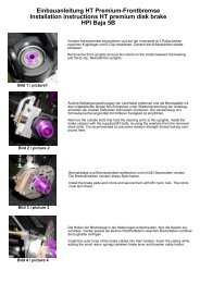
The position 46-52 shows the <strong>Competition</strong> <strong>4WD</strong> Off-Road 1:6 <strong>Baja</strong> <strong>Buggy</strong> item No 66001with a mechanical brake system.Position 46Parts are inbag RBow<strong>de</strong>ncablePressurespringDiskFront right disk brakeIn or<strong>de</strong>r to mount the tuning disk brake, pleaserefer to the <strong>de</strong>scriptions in the enclosedmanual.Mount the components of the disk brakeaccording to the construction stages. Themetric screws need to be secured using themedium screw retention.The brake shafts are available in two differenttypes. When mounting, the surface as well asthe boring for the brake lever must showoutwards or respectively to the brake lining.Alloy bow<strong>de</strong>ncable hol<strong>de</strong>rlongBrake leverHeadless pin3x10BearingbushAlloy brakecaliperStudboltBrakediskScrew3x10Ball bearingflangeGuidingplateScrew3x20Brakeshafts<strong>Competition</strong>brake liningPosition 47Parts are inbag RStopnutM3Front left diskbrakeAlloy bow<strong>de</strong>ncablehol<strong>de</strong>r longBow<strong>de</strong>ncableBrake diskThe servo rods have to be bent off accordingto the gui<strong>de</strong> in the brake gui<strong>de</strong> rail. It must runsmoothly and should not touch at any position.Position 48Parts are inbag RBow<strong>de</strong>ncable hol<strong>de</strong>rBrakegui<strong>de</strong> railBalancecollets<strong>Competition</strong>brake liningStud boltServorodsStopnutM3ServoarmGuidingplateColletHeadlesspinM3x3Screw3x10Brake shaftAdjustment of the brakeIf the throttle/brake of the transmitters is set to thecentral position, it has to be possible to turn thebrake disks in the left and right direction. In directionto the brakes (transmitters), both brakes have toperform an equal braking effect on the disks. If thereis only an one-si<strong>de</strong>d braking effect, tighten thecorresponding bow<strong>de</strong>n cable hol<strong>de</strong>r on the balance.For this purpose you have to loosen the collet. If thebraking effect of both brakes is too much or toolow, loosen the middle collet on the balance andin accordance with shift the balance to the front orto the rear.If there is too much clearance between the brakelinings of the brake disk, you have to tighten the M3stop nut at the outsi<strong>de</strong> brake lining equally.The brake power of the front brake should be a littlebit higher than the brake power of the rear brake.Determine the accurate braking distribution whendriving.
Alloy bow<strong>de</strong>ncablehol<strong>de</strong>r longBow<strong>de</strong>ncableRear left diskbrakeBrake diskPosition 50Parts are inbag RRear right diskbrakePosition 49Parts are inbag RStopnutM3Bow<strong>de</strong>ncable hol<strong>de</strong>rStud boltAlloygearplateAdjustable screwDiskØ6.4ScrewM6x40BrakeshaftScrew3x10Guiding plate<strong>Competition</strong>brake liningBow<strong>de</strong>n cablePressurespringDiskBrakeleverScrew3x10GuidingplateBall bearingflangeBearingbushBrakeshaftsAlloy brakecaliperStudbolt<strong>Competition</strong>brake liningStopnutM3BrakediskPosition 51Parts are inbag RBrake rodsBalanceColletsAdjustable screwAdjustment of the brakeIf the throttle/brake of the transmitters is set to thecentral position, it has to be possible to turn thebrake disks in the left and right direction. In directionto the brakes (transmitters), both brakes have toperform an equal braking effect on the disks. If thereis only an one-si<strong>de</strong>d braking effect, tighten the correspondingbow<strong>de</strong>n cable hol<strong>de</strong>r on the balance.For this purpose you have to loosen the collet. If thebraking effect of both brakes is too much or too low, loose the middle collet on the balance andin accordance with shift the balance to the front orto the rear.If there is too much clearance between the brakelinings of the brake disk, you have to tighten the M3stop nut at the outsi<strong>de</strong> brake lining equally.Position 32Parts are inbag RThe brake rods have to be bent offaccording to the gui<strong>de</strong> in the brakegui<strong>de</strong> rail. It should run smoothly andmust not touch at any position.Position 52Parts are inbag R,NBalanceBrake rodsServoarmHeadlesspin3x3ColletThrottle/brake servo
The position 53-59 shows the <strong>Competition</strong> <strong>4WD</strong> 1:6 <strong>Baja</strong> <strong>Buggy</strong>Item No 66000 with the hydraulic FG-Magura brake system.Position 53Parts are inbag QFront disk brakeBrake diskBrake caliperBrake lineAngleconnectionScrewM3x30All metric screws need to be secured with thread lock fluid.1. Mount 1 angle connection and 1 valve each for each main brakecylin<strong>de</strong>r as <strong>de</strong>scribed in position 54 and 58. The valve must not betighten too much, since the valve seat might could be damaged.2. For the front wheels (in right direction of motion) or respectively forthe rear wheels (in left direction of motion), mount the main brakecylin<strong>de</strong>r in connection with the alloy wheel chocks to the chassis plateas <strong>de</strong>scribed in position 54 and 58.3. Put the brake disks on the square wheel driver, then mount the brakecalipers to the uprights using the M3x30 screws. Then mount the angleconnections and the valves as <strong>de</strong>scribed in position 53 and 56.4. Lay the brake lines according to the illustrations. When laying thebrake lines, please consi<strong>de</strong>r the following items: The brake line mayonly be cut using a sharp knife or the FG ripping knife 09449! Pleasemake sure that the brake lines to the front and rear axle are longenough and that they allow the full steering angle (front axle) respectivelyspring <strong>de</strong>flection. Press the brake lines completely into the anglesrespectively the angle connection. Do not lay the brake lines too closeto hot vehicle components as for example exhaust manifold or shockabsorber.The brake line at the front or rear axle mustnot be pressed or pulled due to vehiclecomponents during <strong>de</strong>flecting or steering.Position 54Parts are inbag QServoarmFront disk brakeColletMain brakecylin<strong>de</strong>rBrakerodsPressurespringThrottlepivot postStopnutM3ScrewM3x18ColletPosition 55Parts are inbag QFront disk brakeBrake line to thefront wheelsRear disk brake
5. Then install the servo rods with pressure spring and collets as <strong>de</strong>scribedin position 54 and 58. Left si<strong>de</strong> in direction of motion for therear brake, right si<strong>de</strong> for the front brake. The servo rods needs to bebent off towards the main brake cylin<strong>de</strong>r according to the mountingheight and size of the servo. The servo rods needs to be bent offaccording to the conditions. Nevertheless, it should run smoothly andmust not touch at any position.6. Fill and bleed the brake system. For filling and bleeding, please referto the <strong>de</strong>scriptions in the enclosed manual attached to the brakes thebrakes.7. Put rubber protective caps on the valve.8. Insert securing rings in the angle connections.Position 56Parts are inbag QBrake diskProtectivecapScrewM3x30Brake caliperBrake lineAngleconnectionRear disk brakePosition 57Parts are inbag QThe brake line at the front or rear axle must not be pressed or pulled due tovehicle components during <strong>de</strong>flecting or steering.Main brakecylin<strong>de</strong>rPosition 58Parts are inbag QAlloy wheelchockScrewM4x10ScrewM4x14ServoarmAngleconnectionBrake line to therear wheelsFix the alloy wheel chock to the mainbrake cylin<strong>de</strong>r using M4x14 countersunkscrews and mount it to the alloychassis using M4x10 countersunkscrews.ColletScrewM3x18StopnutM3Throttlepivot postPressurespringBrakerodsColletMain brakecylin<strong>de</strong>rPosition 59Parts are inbag QT-pieceBrake line to the rear wheels
Position 60Parts are inbag PDrill with diameterof 2.5mm.Plastic componentfor stiffening bracePlastic fixingplateScrewM4x8Si<strong>de</strong> guardAlloy coverBodyclampScrewM4x8Plastic brace fo<strong>rc</strong>overBodyclampAlloyplatefrontScrew2.9x9.5Screw2.9x9.5Roll cage componentfrontAlloy brace long1. Mount the si<strong>de</strong> guards l/r to the alloy chassis using M4x8 pan-headscrews.2. Insert the long alloy braces in the plastic braces for the cover.3. Push the front roll cage components in the long alloy braces.4. Press the rear si<strong>de</strong> of the long alloy braces on the plastic componentsfor the stiffening brace. Insert the roll cage components in theplastic fixing plate and secure it using body clamps.5. Bore out the alloy cover and the front alloy plate at the long alloybraces using a drill with a diameter of 2.5mm and fasten it using2.9x9.5 pan-head screws.The body is <strong>de</strong>livered in transparent poly<strong>car</strong>bonate, therefore it can belacquered according to one’s wishes. We recommend to paint the interiorsi<strong>de</strong> of the body components. This way the color will be protectedand will get glossy shine due to the poly<strong>car</strong>bonate which is on the outsi<strong>de</strong>.Before painting, the body components need to be cleaned. Applythe coat of lacquer very thin and dry well before you spraying onlacquer again. For a multicolor lacquering, always start with the darkestcolor. Only use lacquers which are appropriate for poly<strong>car</strong>bonate. FGColours Sprays are well appropriated to lacquer poly<strong>car</strong>bonate bodies.Position 61Parts are inbag P
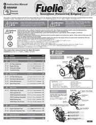
Spare parts list for7300/9 Zenoah engine G230<strong>RC</strong>/047384 Zenoah engine G260<strong>RC</strong>7301/8 Crank case housing A+B, 1 pc.7303/8 Seal ring, 2 pcs7304/2 Bearings, 2 pcs7305/8 Crankshaft gasket, 1 pc.7306/8 Cylin<strong>de</strong>r gasket, 1 pc.7307/9 Cylin<strong>de</strong>r G230/04, 1 pc.7307/10 Tun.-Cylin<strong>de</strong>r f. FG Zenoah 02, 1 pc.7308/9 Piston G230/04, 1 pc.7309/9 Piston ring G230/04, 1 pc.7310 Gudgeon pin, 1 pc.7311 Gudgeon pin clips, 2 pcs7312 Needle bearing, 1 pc.7312/1 Spacer washer, 2 pcs7313/8 Crankshaft complete, 1 pc.7313/1 Key for crankshaft, 1 pc.7314 Hexagon nut, 1 pc.7315 Clutch block <strong>car</strong>rier, 1 pc.7315/1 Screw for <strong>car</strong>rier, 1 pc.7316 Clutch blocks, 2 pcs7317/8 Clutch spring, 1 pc.7318 Dowel screws f. clutch blocks, 2 pcs7319/8 Cooling fan/G230/260<strong>RC</strong>,CY, 1pc.7323/8 Pull start unit/G230/260<strong>RC</strong>,CY, 1pc.7323/9 Starter hous./G230/260<strong>RC</strong>,CY, 1pc.7323/10 Spring assem./G230/260<strong>RC</strong>,CY, 1pc.7323/11 Rope pulley/G230/260<strong>RC</strong>,CY, 1pc.7323/12 Rope/G230/260<strong>RC</strong>,CY, 1pc.7323/13 Starter handle/G230/260<strong>RC</strong>,CY, 1pc.7323/14 Starter ratchet/G230/260<strong>RC</strong>,CY, 1pc.7323/15 Press. spring/G230/260<strong>RC</strong>,CY, 1pc.7323/16 Screw,disks/G230/260<strong>RC</strong>,CY, 3pcs7326/8 Securing ring/G230/260<strong>RC</strong>,CY, 1pc.7328/2 Spark plug cap, 1pc.7328/8 Ignition coil/G230/260<strong>RC</strong>,CY, 1 pc.7330/8 Scews f.silencer M5x60/Zen.,CY,2pcs7332 Silencer gasket /Zenoah,CY, 2pcs7334/8 Screw set engine7335 Insulator gasket/Zenoah,CY, 1pc.7336 Insulator, 1 pc.7337 <strong>Car</strong>buretor gasket/Zenoah,CY, 1pc.7339/8 Screws f.<strong>car</strong>b./G230/260<strong>RC</strong>,CY, 2pcs7340/8 Ci<strong>rc</strong>uit breaker/G230/260<strong>RC</strong>,CY,1pc.7341/8 Engine housing A, 1 pc.7342/8 Engine housing B, 1 pc.7343/8 Spark plug G230 <strong>RC</strong>,CY, 1pc.7344/8 Cable bush./G230/260<strong>RC</strong>,CY, 1pc.7354/8 Spacer block/G230<strong>RC</strong>,CY, 1 pc.7355/8 <strong>Car</strong>buretor/G230/260<strong>RC</strong>,CY, 1pc.7356/8 Air filter/G230/260<strong>RC</strong>,CY, 1pc.7357 Air filter foam, Zenoah,CY 2pcs7361/8 Needle(full-speed)/ spring, 2 pcs7362/9 Needle(idle speed)/spring G230/04,2pcs7363 Diaphragm, 2 pcs7364 <strong>Car</strong>buretor cover, 1 pc.7365 Throttle screw /spring, 2 pcs7366/8 Valve, 1 pc.7368 Leg spring, 1 pc.7370 Diaphragm set, 2 pcs7371 Plastic part with <strong>car</strong>b. nipple, 1 pc.7372 Metal part f. pump, 1 pc.7372/1 Screws f. metal part, 4 pcs7373 Pump, 1 pc.7374 <strong>Car</strong>buretor arm, 1 pc.7375 Screw f. <strong>car</strong>buretor arm, 1 pc.7377/8 Choke shaft w. screw, 2 pcs7378/8 Choke flap, 1 pc.7379/8 Choke lever, 2 pcs7385/1 Cylin<strong>de</strong>r 26 ccm, 1 pc.7385/2 Piston 26 ccm, 1 pc.7385/3 Piston ring 26 ccm, 1 pc.7385/4 Gudgeon pin 26 ccm, 1 pc.8344/1 Coupling flange Solo/Zeno horizontal8345 Coupling flange Zenoah verticalFG Mo<strong>de</strong>llsport-Vertriebs-GmbHSpanningerstr. 273650 Winterbach-GermanyPhone: +49 7181 9677-0Fax: +49 7181 9677-20info@fg-mo<strong>de</strong>llsport.<strong>de</strong>www.fg-mo<strong>de</strong>llsport.<strong>de</strong>7356/8735773707372737373717372/17377/87378/8without illustrationAbb. 7328/2plug cap7379/87343/87342/87307/97307/107385/17330/87340/87323/127323/137323/107323/167323/157317/87339/87362/97315/173157354/87361/87366/8 7367/8736873657365/97355/87364733773637374/7375733673357309/97385/37306/87312/17308/97385/273107385/47312731173327334/87344/87341/87334/87328/87323/97334/87323/147323/117326/87304/27313/8731473167303/87313/9 7303/87301/87318 8344/17319/87305/883457334/87301/8
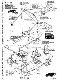
Explo<strong>de</strong>d diagram forFG <strong>Baja</strong> <strong>Buggy</strong> <strong>Competition</strong> <strong>4WD</strong>/ 1:6Item No 66000, 6600166292/366292/266291/366291/2Rear spoiler06421/05Decal 6615566303rear6738/36734/36484/16484/570886481/5 6481/66481/3 6481/466305front7091/26092 6481/1Body <strong>Baja</strong>-<strong>Buggy</strong> <strong>4WD</strong>66150/017087/1709360215/56914/966288602366022/16914/96738/36914/96924/1660237602356738/4 6920/256739/4602336734/4 6013662006738/46738/46628566285/166240 662418093662516118/866258601166287 6734/466305 6920/166625660136738/466286662536925/86925/30 662576912/166926/16662526734/86912/166932/146720/406734/56069/2849566254 662556624284866929/304493/666260 7080/36067/2100318499/17080/28600/5 66250 6920/1460246924/20662431097/16916/136932/20 4493/2 4493/5 6739/38493/57102/56932/1460686914/9662444412 6066/26939/560516624566250/15014/46738/46026/1 6738/3662687100 6930/25 6916/22 601366260/16732/54493/16939/5 66266 66271 6932/126028/1 6025/2602301097662656626766270/26932/1266226/26930/2066270/14493/46917/64472/366270/36029/76734/46925/146078/57475/26742662754429/2Kreuzgelenk4437 4429/26732/66925/86733/66932/20kompl. 6113 6922/25 4466 6734/56739/46922/25 6734/5 66230
6926/167384 66218/16464/46465/16912/136912/136912/166912/16734866238/266238/1601360336930/256916/226932/146922/3044374429/24472/36622666226/26733/6662306078/56077/86078/561136079/144127080/27080/36080/16069/26479/16479/26928/3662251097/171006075/56732/56939/56930/256620066235603166236662376036/5662206622166222662236920/146925/146734/46925/206621271006075/56732/51097/1 60209/51097/16920/1466205662068493/58486662086620766258/584956066/26067/260686932/20663036738/56739/56926/256924/167071/17071/26496/4662136925/206925/86734/48499/18600/544914472/26100/34472/3443744374429/24429/26734/56738/56922/256922/306725/256738/46734/4662106912/136912/166451/46451/38345602060206928/36928/3662466738/36739/36738/5 6485/16726/40603860386920/146920/1473157315/1 731674726040/56745674564326930/5662176930/56734/46925/306621664906492/16034/1 6729/50602386023960239/1602406733/66723/166717/166717/166733/126720/40662116734/46925/10662156037/16925/146927/106727/406137/16137/174746036/56036/56734/67317/8731873185019/16534/26294/1733271196402/16291/36291/36292/26930/56930/5
Spare part list for N° 66000, 66001Item N° DescriptionPart list for <strong>Competition</strong> <strong>4WD</strong> Off-Road 1:6 <strong>Baja</strong> <strong>Buggy</strong>,status 15.05.08Item N° Description01097/01 Gui<strong>de</strong> bush with collar, 6pcs04412 Protective bellow for dogbones, 2pcs04429/02 Taper disk 5mm boring, 2pcs04437 Alloy ball-and-socket joint Ø5/M8, 2pcs04466 Ball-type nipple f. alloy wishbone, 2pcs04472/02 Hexagon nut M8/left, 2pcs04472/03 Hexagon nut M8/right, 2pcs04491 Rear lower alloy wishbone wi<strong>de</strong>, 1pce04493/01 Alloy servo saver A 04, 1pce04493/02 Alloy servo saver B 04, 1pce04493/04 Flange bush 10/20x12 f. all. servo saver, 1pce04493/05 Gui<strong>de</strong> bush 7x10x14 f. all. servo saver B, 1pce04493/06 O-rings f. servo saver Ø6x4, 4pcs05014/04 Servo mount plate Futaba/JR, 2pcs05019/01 Pressure spring 0,4x5x25mm, 2pcs06011 Si<strong>de</strong> guards l./r. each 1 pce06013 Body clips, 10pcs6020 Collets 2,1 mm, 5pcs06022/01 Flexible aerial and mount, 1pce06024 Servo saver pivot, 1pce06025/02 Servo saver spring new, 1pce06026/01 Rods M4x51mm, 2pcs06028/01 Track rod right/left 1:6, 74mm, 2pcs06029/07 Ball-and-socket joint for M6 new, 4pcs06031 Wing mount, 1pce06033 Wing mount, 1pce06034/01 Plastic part f. stiffening brace, 2pcs06036/05 FG Bearings 10x19x7 with grease filling, 2pcs06037/01 Steel fixing plates, 2pcs06038 Engine mount screws, 4pcs06040/05 FG Bearings ,10x22x7 with grease filling, 2pcs06051 Dampening rubber, 4pcs06066/02 Differential gearwheel A reinfo<strong>rc</strong>ed, 2pcs06067/02 Differential gearwheel B reinfo<strong>rc</strong>ed, 2pcs06068 Bevel differential gear axle, 1pce06069/02 Ball diff. axle, 1pce06075/05 Rear upper wishb.pin har<strong>de</strong>ned 6x65mm, 2pcs06077/08 Distance bush for rear upright, 2pcs06078/05 FG Bearing 8x22x7 with graese filling, 2pcs06079/01 Ball driving axle, 1pce06080/01 Balldriving shaft rear 96,5mm, 1pce06092 Spring plate, 2pcs06100/03 Turnbuckle right/left, 32 mm, 2pcs06113 Wheel nuts M6, self-locking, 10pcs06118/08 Alloy battery brace 80mm, 1pce06137/01 Bolt f. gear unit 24,5/26,5mm, 3pcs06291/03 Fixing wire f. tuning pipe, 2pcs06292/02 Manifold f. Tuning pipe 1:6 black, 1pce06294/01 3-unit Tuning pipe Stadium, 1pce06402/01 Exhaust hose new 21x25x50mm, 1pce06421/05 Poly<strong>car</strong>bonate rear spoiler f.1:6 OR, set06432 Steel gearwheel 18 teeth, 1pce06451/03 Air filt. adapt.f. Zen.G230/G260<strong>RC</strong>,CY23/26, 1pce06451/04 O-rings f. air filter adapt.19x1,5/ 57x2,5 , 2pcs06464/04 Foam filter, 2pcs06465/01 Filter cover, 1pce06479/01 Rear alloy 08 upright left, 1pce06479/02 Rear alloy 08 upright right, 1pce06481/01 Alloy shock abs. housing 2000,long,1pce06481/03 Adjustable ring, 2pcs06481/04 O-ring 20x1,5mm, 4pcs06481/05 Sheet gasket, 2pcs06481/06 O-ring 15x1mm, 4pcs06484/01 O-rings f.alloy shock abs.pist.14,8mm,5pcsItem N° Description Item N° Description Item N° Description06484/05 Alloy shock absorber piston 14,8mm, 2pcs06485/01 Alloy eng. mount sm. 1:6/Zen. G230/260, 1pce06490 Alloy gearwheel adapter, 1pce06492/01 Alloy gearwheel 46 teeth, 1pce06496/04 Gui<strong>de</strong> bushes f. front axle mount, 8pcs06510/20 Oil for shock absorber 2000, 1pce.06534/02 Throttle pivot post 2,1 mm, set06716/25 Pan-head tap.screws, 4.2x25mm, 15pcs06717/16 Lenticular flange head screw M6x10, 5pcs06720/40 Recessed countersunk screw M4x40mm, 10pcs06723/16 Recessed countersunk screw M6x16mm, 10pcs06725/25 Socket head cap screw M4x25mm, 10pcs06726/40 Socket head cap screw M5x40mm, 10pcs06727/40 Sock. head cap screws,M6x40mm, 10pcs06729/50 Headless pin M4x50, 8pcs06732/05 Retain.washers-spring steel, 5mm, 15pcs06732/06 Retain.washers-spring steel, 6mm, 15pcs06733/06 Thread pin M6x6 , 10pcs06733/12 Pan-head cap screw M5x12, 10pcs06734/03 Washers, steel 3,2mm, 15pcs06734/04 Washers, steel 4.3mm, 15pcs06734/05 Washers, steel 5.3mm, 15pcs06734/06 Washers, steel 6.4mm, 15pcs06734/08 Washers, steel 8,4mm, 15pcs06738/03 Self-locking hexagon nut, M3, 15pcs06738/04 Self-locking hexagon nut, M4, 15pcs06738/05 Self-locking hexagon nut, M5, 15pcs06739/03 Hexagon nut M3, 15pcs06739/04 Hexagon nut M4, 15pcs06739/05 Hexagon nut M5, 15pcs06742 Shim rings 7x13x0,3mm, 10pcs06745 Shim rings 10x16x1mm, 10pcs06912/13 Counters. sheet met. screw w. Torx 4,2x13, 20pcs06912/16 Counters. sheet met. screw w. Torx 4,2x16, 20pcs06914/09 Pan-head sheet met. screw w. Torx 2,9x9,5, 15pcs06916/13 Pan-head sheet met. screw w. Torx 4,2x13, 15pcs06916/22 Pan-head sheet met. screw w. Torx 4,2x22, 15pcs06917/06 Pan-head flange screw w. Torx M3x6, 10pcs06918/10 Countersunk screw w. Torx M3x10, 10pcs06918/20 Countersunk screw w. Torx M3x20, 10pcs06920/10 Countersunk screw w. Torx M4x10, 10pcs06920/14 Countersunk screw w. Torx M4x14, 10pcs06920/16 Countersunk screw w. Torx M4x16, 10pcs06920/25 Countersunk screw w. Torx M4x25, 10pcs06922/25 Countersunk screw w. Torx M5x25, 10pcs06922/30 Countersunk screw w. Torx M5x30, 10pcs06924/16 Pan-head screw w. Torx M3x16, 10pcs06924/20 Pan-head screw w. Torx M3x20, 10pcs06925/08 Pan-head screw w. Torx M4x8, 10pcs06925/10 Pan-head screw w. Torx M4x10, 10pcs06925/12 Pan-head screw w. Torx M4x12, 10pcs06925/14 Pan-head screw w. Torx M4x14, 10pcs06925/20 Pan-head screw w. Torx M4x20, 10pcs06925/30 Pan-head screw w. Torx M4x30, 10pcs06926/16 Pan-head screw w. Torx M5x16, 10pcs06926/25 Pan-head screw w. Torx M5x25, 10pcs06927/10 Pan-head screw w. Torx M6x10, 5pcs06928/03 Headless pin w. Torx M3x3, 15pcs06929/30 Headless pin w. Torx M4x30, 15pcs06930/05 Headless pin w. Torx M5x5, 15pcs06930/20 Headless pin w. Torx M5x20, 15pcs06930/25 Headless pin w. Torx M5x25, 15pcs06932/12 Socket head cap screw w. Torx M4x12, 10pcs06932/14 Socket head cap screw w. Torx M4x14, 10pcs06932/20 Socket head cap screw w. Torx M4x20, 10pcs07058/01 Body screws Torx w. stop nuts, 15pcs07071/01 Stabilizer 5mm rear, 1pce07071/02 Plastic brace f.stabilizer long, 6pcs07080/02 Balls f. driving shaft, 6pcs07080/03 Distance disks, 4pcs07087/01 Lower shock retaining, short 2pcs07088 Volume compensation f.shock absorb.,2pcs07091/02 Threa<strong>de</strong>d piston rod, 2pcs.07093 Silicone O-rings, 12 pcs07100 Adjusting clips for front axle, 16pcs07102/05 Front wishb. pin, har<strong>de</strong>ned 6x87mm, 2pcs07119 Hose clamps, 4pcs07315 Clutch block <strong>car</strong>rier / Zenoah07315/01 Screw f. <strong>car</strong>rier/ Zenoah, 1pce07317/08 Clutch spring/G230 <strong>RC</strong>, 1pce07318 Dowel screws f. clutch blocks/Zenoah, 2pcs07332 Silencer gasket / Zenoah,CY, 2pcs07348 Tank complete without ventilation, 1pce07384 FG Zenoah engine G260<strong>RC</strong>07472 Tuning clutch bell har<strong>de</strong>ned, 1pce07474 Alloy gear plate, 1pce07475/02 Alloy joint ball Ø10x10.75mm, 2pcs08093 Brake gui<strong>de</strong> rail, 1pce08345 Coupling flange Zenoah 1:6, 1S.08474/06 Alloy bow<strong>de</strong>n cable hol<strong>de</strong>r new, 2pcs08486 Alloy diff. housing, 1pce08493/05 FG ball bearing 15x28x7 with grease filling, 2pcs08495 Distance disks f. alloy diff., 4pcs08499/01 Needle bearing f. diff. 2pcs08600/05 Bronze bush 8x12x5, 2pcs09438 Hydr. brake system f. front and rear axle <strong>4WD</strong>, set09438/01 Alloy wheel chock f. hydr. brake 1:6, 1pce10031 Distance bolts 9x57, 3pcs60209/05 <strong>Baja</strong> tires S wi<strong>de</strong> glued, 2pcs60215/05 <strong>Baja</strong> tires M narrow glued, 2pcs60230 Front bumper <strong>Baja</strong>, 1pce60233 Roll cage parts, front 2pcs60235 Alloy plate front, 1pce60236 Alloy cover, 1pce60237 Plastic brace for cover, 2pcs60238 Spark plug cover, 1pce60239 Plastic braces long 2pcs60239/01 Plastic braces short, 2pcs60240 Body mount <strong>Baja</strong> rear, 2pcs66150/01 Body <strong>Baja</strong> <strong>Buggy</strong> <strong>4WD</strong> transparent, 1pce66155 Mo<strong>de</strong>l stickers f. <strong>Baja</strong> <strong>Buggy</strong> <strong>4WD</strong>, Set66200 Alloy chassis <strong>4WD</strong>, 1pce66205 Alloy rear axle mount left <strong>4WD</strong>, 1pce66206 Alloy rear axle mount right <strong>4WD</strong>, 1pce66207 Plastic rear gear disk, 42 teeth <strong>4WD</strong>, 1pce66208 Steel gearwheel 48 teeth <strong>4WD</strong>, 1pce66210 Rear axle cover <strong>4WD</strong>, 1pce66211 Gearwheel cover-gear box <strong>4WD</strong>, 1pce66212 Alloy connection brace-gear box <strong>4WD</strong>, 1pce66213 Rear alloy damper plate <strong>4WD</strong>, 1pce66215 Alloy engine mount big <strong>4WD</strong>, 1pce66216 Tuning gear shaft har<strong>de</strong>ned <strong>4WD</strong> , 1pce66217 Steel gearwheel 14 teeth narrow, 1pce66218/01 Basic body f. inlet silencer, 1pce66220 Housing f. alloy tensioning pulley left <strong>4WD</strong>, 1pce66221 Housing f. alloy tensioning pulley right <strong>4WD</strong>, 1pce66222 Bearing shaft f. tension. pulley housing <strong>4WD</strong>, 1pce66223 Plastic bearing seat <strong>4WD</strong>, 2pcs66225 Rear upper alloy wishbone <strong>4WD</strong>, 1pce66226 Wishbone thread rod M10/M8x84mm, 2pcs66226/02 Hexagon nut M10 left, 2pcs66230 Square wheel driver 14mm/M6, 2pcs66235 Lower part belt channel, 1pce66236 Upper part belt channel, 1pce66237 Toothed belt, 1pce66238/01 Lower tank mount <strong>4WD</strong>, 1pce66238/02 Upper tank mount, 1pce66240 Alloy <strong>RC</strong> plate <strong>4WD</strong>, 1pce66241 Receiver box <strong>4WD</strong>, 1pce66242 Distance bolt 48mm, 4pcs66243 Bolt for battery hol<strong>de</strong>r <strong>4WD</strong>, 2pcs66244 Ball-and-socket joint 7mm f.M4 , 4pcs66245 Steel ball 7mm, 4pcs66246 Throttle rods <strong>4WD</strong>, set66250 Alloy front axle housing left <strong>4WD</strong>, 1pce66250/01 Gui<strong>de</strong> f. stabi. front <strong>4WD</strong>, 2pcs66251 Alloy front axle housing right <strong>4WD</strong>, 1pce66252 Toothed belt wheel 12 teeth <strong>4WD</strong>, 1pce66253 Deflection roller 16mm, 1pce66254 Bearing shaft 6x50mm, 1pce66255 Ball bearing 6x16x6, 2pcs66256 Front plastic toothed belt wheel 42teeth <strong>4WD</strong>,1pce66257 Front plastic stop disk left <strong>4WD</strong>, 1pce66258 Plastic stop disk right <strong>4WD</strong>, 1pce66258/05 Alloy stop disk right <strong>4WD</strong>, 1pce66260 Front stabilizer 4mm <strong>4WD</strong>, 1pce66260/01 Plastic brace f. stabi. short 4/4 mm twisted, 4pcs66265 Front lower alloy wishbone <strong>4WD</strong>, 1pce66266 Front upper alloy wishbone <strong>4WD</strong>, 1pce66267 Wishb. thread rod M10/M8x66mm, 2pcs66268 Front lower wishb. pin har<strong>de</strong>ned <strong>4WD</strong>, 2pcs66270/01 Front alloy upright right / left <strong>4WD</strong>, 1pce66270/02 Front alloy steering lever <strong>4WD</strong>, 1pce66270/03 Plastic steering stop, 2pcs66271 Ball bearing 17x26x7, 2pcs66275 Universal joint f. front axle <strong>4WD</strong> compl., 1pce66285 Reinfo<strong>rc</strong>ing plate f. front axle, 1pce66285/01 Alloy distance SW10x7, 2pcs66286 Plastic fixing plate, front <strong>4WD</strong>, 1pce66287 Front alloy shock mount <strong>4WD</strong>, 1pce66288 Alloy brace long <strong>4WD</strong>, 2pcs66291/02 Shock absorber seal M20 for M5, 2pcs66291/03 Dampening rubber f.shock absorber seal f.M5, 5pcs66292/02 Shock absorber seal M20 for M4, 2pcs66292/03 Dampening rubber f. shock absorber seal M4, 5pcs66303 Damper spring red, 2,0x100mm 2pcs66305 Damper spring violet, 2,2x100mm 2pcs