Monitor_Vessel_Manual.pdf - Velcon Filters
Monitor_Vessel_Manual.pdf - Velcon Filters
Monitor_Vessel_Manual.pdf - Velcon Filters

You also want an ePaper? Increase the reach of your titles
YUMPU automatically turns print PDFs into web optimized ePapers that Google loves.
TABLE OF CONTENTSGeneral Description (1507C-R4, 01/09).........................................................................2Installation of <strong>Vessel</strong>..............................................................................................3Start-Up Procedure.................................................................................................4Operating Information............................................................................................5Cartridge Change or Inspection Procedures ..........................................................7Sump Checks..........................................................................................................8Installation Instructions 09-879 (1565).....................................................................9Installation Instructions 1935 05/04........................................................................10Important Operating Procedures 09-923 (1839).....................................................13Cartridge Changeout Curve 1846 ........................................................................14ACCESSORIES / APPENDIXFuel <strong>Monitor</strong> Cartridges (1962)<strong>Monitor</strong> Interlock Principle (1882)M:\SHARED\MKTGSERV\WEB SITE\MONITOR TOC-R1 Generic.doc
GENERAL DESCRIPTIONThe <strong>Velcon</strong> <strong>Monitor</strong> <strong>Vessel</strong> that you have received consists of the vessel, monitorcartridge cartridges and accessory equipment to meet your specific requirements.Descriptive literature covering the accessories is included elsewhere in this manual.A <strong>Velcon</strong> <strong>Monitor</strong> <strong>Vessel</strong> is designed to house CDF ® <strong>Monitor</strong> cartridges. Thecartridges are mounted on a flat deck plate. The product being filtered enters throughthe inlet nozzle. The flow of the product is from outside to inside the cartridges.CDF ® <strong>Monitor</strong> CartridgesThese cartridges absorb water and filter solids from avgas and jet fuel. They removeparticles down to 1 micron and provide protection against water slug transmission byrestricting fuel flow when saturated. The cartridges are tested and qualified to EI1583 4 th Edition.PLEASE NOTE: If interlock is present on the housing, please refer also to “<strong>Monitor</strong>Interlock Operating Principle” data sheet #1882 in Appendix.Fully qualified to EI 1583 for <strong>Monitor</strong> <strong>Vessel</strong>s.Caution: Do not use water absorbing cartridges with pre-mixed fuelcontaining anti-icing additives.1507C-R4 1/09 PAGE 2
INSTALLATION1. Identify the vessel inlet and outlet by the markings provided on the vessel piping.The vessel must be installed in the correct direction of flow for the filters tofunction properly and to avoid damage to the system.2. Inlet and outlet piping should be carefully aligned to avoid stressing the vesselconnections during installation. Installation of valves on either side of the vessel isrecommended so that it can be independently drained for cartridge change orinspection.3. Bolt the vessel in place so that it is secure and stable.4. Carefully install correct gaskets on the inlet and outlet and connect to the inlet andoutlet piping.5. Connect any accessories that are not already installed. See Parts List andliterature as required.6. Cartridges are normally packed separately. Open the vessel cover and installcartridges by inserting the snout ends into the deckplate holes. Seat eachcartridge firmly by giving it a slight twisting motion while pushing it into the hole.7. Install the spider assembly over the top ends of the cartridges as shown on thegeneral outline drawing at the back of the manual. Tighten the spider hold downnuts snugly, but do not over-torque. Over-torquing could result in bent ordamaged cartridges.8. Be sure the cover gasket is in place and properly aligned. Replace cover andsecure tightly.9. NOTE: <strong>Vessel</strong>s must be provided with pressure relief valves if the systemhas positive displacement pumps upstream or automatic shut-off valvesdownstream of the vessel.1507C-R4 1/09 PAGE 3
START-UP PROCEDUREIf the <strong>Velcon</strong> <strong>Monitor</strong> <strong>Vessel</strong> has the accessories listed below, they should be placedin the following positions:1. <strong>Manual</strong> drain valves closed.2. <strong>Manual</strong> air eliminator valve open.3. The inlet and outlet pipe valves closed.4. The pressure gauge valve to OFF position. For vessels equipped with selectorvalves, this is done by turning the handle outward so that the arrow points towardthe vessel.For information on operation of accessories, turn to Accessory Instructions in theback of the manual.After the valves have been positioned as outlined, the unit is ready to be filled.The following operating instructions can be used for initial start-up and forsubsequent start-ups after installation of replacement cartridges or servicing of theunit:1. Start the system pump.2. Slightly open the inlet valve, allowing the vessel to slowly fill with fluid.3. If the unit is equipped with a manual air eliminator valve, leave the valve openuntil the fluid flows from the opening; then close. If equipped with an automatic aireliminator, the unit is filled when the eliminator stops flowing air.4. When the <strong>Velcon</strong> <strong>Vessel</strong> is filled with fluid, slowly open the valve on the outletline. Then slowly open the inlet valve fully.5. When the unit is in operation, open the pressure gauge, take a differentialpressure reading, and record the reading. If there is no pressure differential, thesystem should be shut down and the vessel inspected for broken seals orpossible cartridges left out. See Differential Pressure Readings below.1507C-R4 1/09 PAGE 4
OPERATING INFORMATION1. (Your Company Maintenance and/or Quality Control procedures may providealternate instructions on these matters.) <strong>Velcon</strong> recommends the operatingprocedures and changeout as outlined in “Operation of <strong>Vessel</strong>s Containing WaterAbsorbing Cartridges for Aviation Fuel (ACO/ACI/CDF ® )” Form #1839 includedelsewhere in this manual, and is also supplied with each cartridge shipment.2. DIFFERENTIAL PRESSURE READINGS. Differential pressure is the differencebetween the pressure upstream and downstream of the vessel. Differential pressure(DP) increases when contaminant or water is filtered by the monitor cartridges andcauses flow restrictions. If operating at less than rated flow, record DP and flow rate,then calculate corrected DP at rated flow rate (using <strong>Velcon</strong>’s Cartridge ChangeoutCurve Label – Form 1846), also included elsewhere in this manual.Reading should be taken when the system is flowing at maximum capacity. If thevessel is equipped with a direct reading differential pressure gauge, the readingshown on the gauge is the differential pressure across the vessel.If the vessel is equipped with a pressure gauge and a selector valve, use thefollowing procedure for determining differential pressure:A. Turn the handle to the outlet side so that the arrow points toward the inlet.Record gauge reading as “Inlet Pressure.”B. Turn handle toward the inlet side so that arrow points toward the outlet. Recordgauge reading as “Outlet Pressure.”C. Subtract outlet pressure from inlet pressure to determine differential pressure.D. Turn handle outward so that arrow points toward vessel which is the “OFF”position. To avoid damage to the pressure gauge, leave the handle in the“OFF” position when readings are not being taken.Differential pressure readings should be taken at least once during every operatingweek and more frequently in high throughput installations or when the differential isincreasing rapidly. Records of the differential pressure and throughput should bemaintained to determine when cartridges should be changed.1507C-R4 1/09 PAGE 5
A sudden drop in pressure differential is an indication of a possible problem. Checkfirst to be sure that the readings were taken at equivalent flow rates. If so, shut thesystem down, open the vessel, and inspect for the following:A. Collapsed or ruptured cartridges caused by severe pressure differential orshocks in excess of design limits.B. Ruptured seals. Check to see that all O-ring seals are in place and have thesame alignment as when the cartridges and parts were installed.C. If either of the above are observed, check the system for possible hydraulicshock conditions. If the system is not provided with adequate surge controls,the sudden start-up of a high-pressure pump can create extremely high shockloads that may exceed the design of these components.1507C-R4 1/09 PAGE 6
3. CARTRIDGE CHANGE OR INSPECTION PROCEDUREA. Shut off the pump.B. Close the inlet and outlet pipe valves.C. Open drain valves and remove product from the vessel.D. Open the manual air eliminator valve. This will permit the unit to drain faster.E. Open cover and inspect cover gasket – replace gasket if it is damaged.F. Remove spent cartridges for cartridge change.G. Wipe off or wash down any foreign matter from the vessel interior.H. Install cartridges in all mounting holes. Use a slight twisting motion whilepushing each cartridge into place.I. Install the spider assembly over the top ends of the cartridges as shown on thespider schematic at the back of the manual. Tighten the spider holding downnuts snugly, but do not over-torque. Over-torquing could result in bent ordamaged cartridges.J. Check cover gasket for alignment, replace cover and secure tightly. The vesselis now ready for the start-up procedure.1507C-R4 1/09 PAGE 7
SUMP CHECKSWhether or not the vessel is equipped with an automatic drain valve*, the sumpshould be manually drained on a regular basis to remove any collected water. Thisshould be done at least once each operating day and more often if required toprevent water carryover. Aircraft Fueling Regulations will govern the frequency ofsump checks for into-aircraft equipment.Draining or sump sampling should preferably be done during flow though the vessel,or at least when the vessel is pressurized. This will provide velocity to removecollected water from any flat surfaces to the drain valve, and will also prevent air fromentering the vessel. Carefully open the drain valve as far as possible without causingspillage. Drain off into a white bucket until all water is removed. Even small quantitiesof water should be kept drained from kerosene or diesel products to prevent microbialgrowth at the fuel/water interface.*NOTE: VELCON DOES NOT RECOMMEND, WARRANTEE, OR SELLAUTOMATIC DRAIN VALVES. They do not completely drain the water from thesump and they malfunction too often resulting in costly fuel spills and subsequentenvironmental problems.USE ONLY VELCON FILTERS INC. CARTRIDGES IN THIS VESSEL. VELCONCANNOT WARRANT PERFORMANCE IF ANY OTHER MANUFACTURER’SCARTRIDGES ARE USED.To reorder cartridges and replacement parts or to obtain further information contactyour <strong>Velcon</strong> <strong>Filters</strong>, Inc. representativeOrVELCON FILTERS, INC.1210 Garden of the Gods RoadColorado Springs, CO 80907-3410Phone: 719-531-5855Fax: 719-531-5690E-mail: vfsales@velcon.comWeb site: www.velcon.com1507C-R4 1/09 PAGE 8
1210 Garden of the Gods Rd., Colorado Springs, CO 80907Phone: (719) 531-5855 FAX: (719) 531-5690e-mail: vfsales@velcon.com / web site: www.velcon.comINSTALLATIONInstructionsCAUTION: DO NOT USE WITH PRE-MIXED JET FUELCONTAINING ANTI-ICING ADDITIVES(Di-EGME, FSII, Fizzy ® , Prist ® )CDF ® SERIES CARTRIDGES1. Stop the pump and close valves in inlet and outlet piping to isolate housing.2. Open bottom drain valve(s) and top air vent to drain product from housing.3. Open cover and inspect cover gasket. Replace gasket if it is damaged.4. Remove spider and used cartridges.5. Clean any foreign matter from the interior of the vessel.6. Remove the new cartridges from their poly-bags - handle by endcaps only.7. Lubricate the o-ring end of each filter with clean fuel to help ensure a smooth, secure fit into thedeckplate. Gently push new cartridges into housing with a twisting motion so that the o-ring sealseats inside the outlet orifice. Push the cartridge in until the plastic shoulder is flush against thebulkhead of the housing.8. Reinstall the spider.NOTE: The retaining spiders in most multi-cartridge housings do not insure that the cartridgesare seated. Check each cartridge to insure that it is firmly seated against the bulkheadbefore securing the spider. Torque the spider onlyHAND-TIGHT. DO NOT OVER-TORQUE the spider.9. Replace the cover and close the bottom drain valve(s).10. Start the system pump.11. SLIGHTLY open the inlet valve, allowing the housing to SLOWLY fill with fluid.12. If the unit is equipped with a manual air vent valve, leave the valve cracked open until fluid flowsfrom the opening; then close quickly. If equipped with an automatic air eliminator, the unit is filledwhen the eliminator stops flowing air.13. When the vessel is filled with fluid, fully open the inlet valve and then SLOWLY open the outletvalve.14. After changing cartridges circulate flow through vessel for at least 3 minutes. Return fuel to storage.Use millipores to check for fibers and also check hose end strainers. Remove any debris that maybe present.OPERATING PROCEDURESPlease refer to Operating Procedures for Water Absorbing Cartridges,<strong>Velcon</strong> PN 09-923, Form 1839(Also refer to your company guidelines)© 2008 <strong>Velcon</strong> <strong>Filters</strong>, Inc.Due to <strong>Velcon</strong> <strong>Filters</strong>, Inc. continuing product improvement, drawings,specifications, and pictures are subject to change without notice.For information on recycling used filters, contact FILCare, 719-499-13791565-R18 06/08P/N 09-879
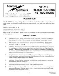
1210 Garden of the Gods Rd, Colorado Springs, CO 80907Phone: (719) 531-5855 FAX: (719) 531-5690E-mail: vfsales@velcon.com / web site: www.velcon.comINSTALLATIONInstructionsTORQUE REQUIREMENTS FOR VESSELSWITH “O-RING CLOSURE”Bolted pressure vessel closuresoperate on the premise that the joint isclamped closed with a force sufficientto resist the internal pressure yet stillmaintain a seal. The clamping force,or pre-load, is applied by the closurebolts and its magnitude is controlledby the torque applied. Application ofthe correct preload is essential tomaintaining a positive seal andavoiding closure failures from fatigueor overstressed vessel components.The short term, and most obviouseffect of grossly under-torqued boltsis insufficient clamping force resultingin a leaking closure. A more ominousresult of under-torqued bolts insystems which see a great number ofpressure cycles (such as refuelers,loading racks etc.), is bolt fatiguefailure. Repeated applications of stressto the bolt eventually create a smallcrack at the surface of the bolt whichcontinues to grow until the bolt breaksand the closure fails.values for lubricated bolts for commonsizes used for vessel closures. Alwaysuse lubricated bolts, as this reduces therequired torque, improves torqueaccuracy, and retards corrosion.A common cause of inaccurate bolttorque is inappropriate bolt torquingprocedures. Key elements to theprocedure are application of the torquein stages and in a specific crosstorquingsequence. For mostapplications, torque is applied to allbolts to 30% of full torque, then to allbolts to 60% of full torque, and finallyto all bolts to 100% of full torque.Each torquing cycle is carried out inthe applicable cross-torquingsequence. Torquing sequences varywith the number of bolts on the cover.The tightening pattern is as follows:Tighten two bolts diametricallyopposite from each other, thentighten a second pair of boltsdiametrically opposite eachother, approximately 90 degreesaway from the first pair, and soon until all bolts have beentightened.Using a clock as an example, thesequence would be:12, 6, 9, 3, 11, 5, 10, 4, 7, 1, 8, 2.On large vessels, the cross-torquingprocess is tedious but the addition ofa second operator applying torqueimproves the situation vastly.Correct closure torquing will result inmany years of trouble-free vesseloperation. Occasional inspections forbolt cracks or clip damage is goodpractice to detect possible closureproblems before they occur. Moredetailed or specific information onbolt torquing requirements andprocedures can be obtained by callingJim Head at (719) 528-7255. •It is a good idea to re-torque theclosure bolts after they have been inuse for a month or so to ensure the jointhas not “relaxed” and the preloadreduced.Over-torquing closure bolts will resultin breaking or bending vessel bolt clipsor actually breaking the bolt itself.Table One lists guideline torqueBolt Diameter (inches)TABLE ONE*Recommended Torque (ft-lb)1/2" 203/4" 451" 1001-1/4" 160*NOTE: These recommended torque values are only for vesselswith an O-Ring closure.©2006 <strong>Velcon</strong> <strong>Filters</strong>, Inc.1935 05/04
1210 Garden of the Gods Rd., Colorado Springs, CO 80907Phone: (719) 531-5855 FAX: (719) 531-5690Toll-free: (800) 531-0180e-mail: vfsales@velcon.com / web site: www.velcon.comIMPORTANTOPERATINGPROCEDURESOperation of <strong>Vessel</strong>s ContainingWater Absorbing Cartridges (ACO/ACI/CDF ® ) for Aviation FuelNOTE: If pump discharge pressure can exceed 25 psi, do not use this cartridge unless pressure gaugesare installed to measure the differential pressure. For ALL systems, differential pressure gauges arestrongly recommended, along with daily monitoring of dP. If the gauges cannot be observed easilyduring flow, an electronic monitoring method, with flow shutdown capability, is recommended.NOTE: Always ensure that the vessel and drain plug are properly grounded. If the Aquacon ® cartridge(ACO-xxxxx) is used in a VF-31E, VF-61, VF-61E, or VF-609 or similar sized housings, please refer tothe instructions for the housings in which cartridges are installed for more information.Contact <strong>Velcon</strong> <strong>Filters</strong>, Inc. for more information.Recommended procedures* to follow with water absorbing cartridges in a vessel:1. Reinforce quality control checks and diligently conduct water removal procedures at all locations in thefuel distribution system. This includes daily draining of all sumps, low points, and dead legs in the pipingsystem.2. <strong>Monitor</strong> differential pressure daily - if operating at reduced flow, record differential pressure and flow rateand calculate normalized differential pressure. (See page 2, or Service Bulletin – Vol. 1, No. 2). Change ACO,ACI, & CDF ® cartridges when normalized differential pressure reaches 25 psid. Replace all cartridges if thenormalized differential pressure has dropped 5 psid below the previous reading.3. Sample fuel and check for free water content using the <strong>Velcon</strong> Hydrokit ® or other chemical method in accordancewith your company’s fuel handling procedures. Replace cartridges if the water content exceedsyour company guidelines.4. In converted filter/separator vessels where the deckplate or manifold strength does not meet the 15 bar (220psi) strength required by the IP <strong>Monitor</strong> Spec. 1583, a differential pressure limiting device, set from 25-30psid, should be installed across the vessel.5. Have a spare set of water absorbing cartridges on hand, or available at a nearby <strong>Velcon</strong> Distributor, for theunexpected plug-up.6. If fueling unit is operating consistently below 50% of rated flow then periodically check fueling unit at teststand and check DP at flow rate of 50% or higher and confirm corrected DP.7. After changing cartridges circulate flow through vessel for at least 3 minutes, use millipores to check for fibersand also check hose end strainers.(Continued, over →)*Please also check with your company's fuel handling guidelines and operating procedures.© 2008 <strong>Velcon</strong> <strong>Filters</strong>, Inc.Due to <strong>Velcon</strong> <strong>Filters</strong>, Inc. continuing product improvement, drawings,specifications, and pictures are subject to change without notice.For information on recycling used filters, contact FILCare, 719-499-13791839-R17 07/08P/N 09-923
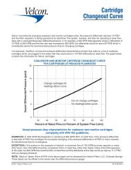
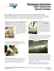
8. As the cartridges begin to restrict the flow due to a water slug, ALL upstream and downstream piping shouldbe checked and purged before resuming operations with a new set of cartridges. Any aircraft involved infueling when the flow through a cartridge is restricted, should also be checked for the possibility of waterreaching the aircraft. Check the tank to determine where the excess water came from, and purge the tank ofany water before resuming operation.9. Cartridges should not be dried and re-used. When water saturated media is dried, it may shrink and crack,leading to possible internal bypass.SERVICE LIFEService life for all water absorbing cartridges, including two (2), five (5) and six (6) inchdiameter cartridges, should be one (1) year, unless stated otherwise by your company’s fuelhandling procedures.*****CAUTION*****DO NOT USE WATER ABSORBING CARTRIDGES WITH PRE-MIXED JET FUEL CONTAINING ANTI-ICING ADDITIVESWARNING: Absorbent-type monitor cartridges will NOT remove water fromfuel containing alcohol-blending agents (commonly called gasohol).For removal of solids, please use <strong>Velcon</strong> particle removal filters specificallymade for gasohol. Consult your <strong>Velcon</strong> representative.For technical support, contact <strong>Velcon</strong> or your authorized <strong>Velcon</strong> distributor.See also www.velcon.comEXAMPLE: A 600 GPM monitor vessel is operating at 300 GPM (50% of system flow limit).If the pressure differential is less than 8 PSID, the cartridges do not require changing;however, if the pressure differential is 8 PSID or more, or if the cartridges have been inservice for one year, the cartridges are due for changeout.Form 1846 - Cartridge Changeout Curve for Aquacon ® cartridges(This form is available as a stick-on decal. Contact <strong>Velcon</strong> for more information.)
EXAMPLE: A 600 GPM monitor vessel is operating at 300 GPM (50% of system flow limit).If the pressure differential is less than 8 PSID, the cartridges do not require changing. However if thepressure differential is 8 PSID or more, or if the cartridges have been in service for one year, thecartridges are due for changeout.1210 Garden of the Gods Road, Colorado Springs, CO 80907-3410Phone: 791.531.5855 • Fax: 719.531.5690 • www.velcon.com© 2008 1846-R5 03/08
APPENDIX /ACCESSORIES
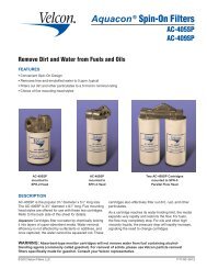
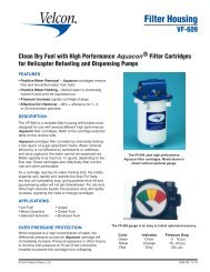
CDF ®Fuel <strong>Monitor</strong> CartridgesN SeriesField Proven:CDF Replacement CartridgesAssure Clean Dry Fuel DeliveryFEATURESCDF-N SERIES are qualified to IP 1583, Fourth Edition, aspecification for Aviation Fuel Filter <strong>Monitor</strong>s.IMPROVED SALT WATER PERFORMANCECONDUCTIVE END CAPS and adhesive for reductionof static charge within the vessel.O-RING SEAL minimizes the possibility of bypassingcontaminated fuel at differential pressures up to 175 psi.RUGGED CONSTRUCTION collapse strength exceeds175 psi differential pressure.DESCRIPTIONThe <strong>Velcon</strong> CDF ® N Series cartridges are designed toprovide superior performance and reliability in standardfuel monitor housings through a unique, patentedcombination of media that absorbs water, filters solidsthat may be present in the fuel, and provides for reducedstatic charge.The cartridge has injection molded endcaps that arebonded to the media and an O-ring seal on the outletend. This minimizes the possibilities of bypassingcontaminated fuel or transmission of water downstreamat low flow rates.As the cartridge removes water and/or dirt from theinfluent fuel there will be an increase in the pressuredifferential along with a decrease in flow rate. Thesechanges are the result of flow restriction caused by dirtfiltration or water absorption in the media. The rate ofthese changes depends on the quantity of water or dirtcontaminants present.*****CAUTION*****DO NOT USE WITH PRE-MIXED FUELS CONTAININGANTI-ICING ADDITIVES.® CDF is a registered trademark of <strong>Velcon</strong> <strong>Filters</strong>, Inc.© 2007 <strong>Velcon</strong> <strong>Filters</strong>, Inc. 1962-R2 03 /07
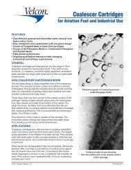
IP Specification 1583 Fourth Edition InformationOur new CDF ® -2xxN Series Cartridges incorporatefeatures that result in increased electrical conductivityto quickly dissipate electrostatic charge across thecartridge. This is in response to the new requirement inthe specification to reduce static charge within the filtermonitor.Another addition to the specification is an optional test todetermine the performance of the cartridge in a salt waterenvironment. The CDF ® N Series successfully passed thefollowing tests:1. ¾ % Sodium Chloride full flow slug test2. ¾ % Sodium Chloride 50 ppm testORDERING INFORMATIONEpoxy BondedConductive PlasticEndcapsHigh StrengthPlastic Center CoreMulti Layers ofAbsorbing andSupport MediaFine Filter MediaProtective OuterWrap• Specify <strong>Velcon</strong> Model Number from table below.CDF Cartridges are packaged 20 per carton.CARTRIDGE SELECTION TABLESPECIFICATIONS AND TECHNICAL INFORMATION CDF ® N SERIES• 175 psid (12 bar) collapse strength• 0.5 micron rating• 160°F maximum operating temperature• Recommended changeout differential pressure = 25 psid• For service life information, please refer to Operating Procedures # 1839or consult your company fuel handling procedures.Replacements for:Cartridge <strong>Velcon</strong> Facet Racor FaudiFlow Rate Model Overall Model Model ModelUSGPM Number Length Number Number NumberFG-205 (-3 or -4) RMO-205-4-E M.2-1345 CDF-205N 5 13 /16” GNG-205 — (/4 or /E)FG-210 (-3 or -4) FMI-10203 M.2-26110 CDF-210N 10 13 /16” GNG-210 FM-10202 (/4 or /E)RMO-210-4-EFG-215 (-3 or -4) FMI-15203 M.2-38715 CDF-215N 15 13 /16” GNG-215 FM-15202 (/4 or /E)RMO-215-4-EFG-220 (-3 or -4) FMI-20203 M.2-51520 CDF-220N 20 13 /16” GNG-220 FM-20202 (/4 or /E)RMO-220-4-EFG-225 (-3 or - 4) FMI-25203 M.2-64225 CDF-225N 25 13 /16” GNG-225 FM-25202 (/4 or /E)RMO-225-4-EFG-230 (-3 or -4) FMI-30203 M.2-77030 CDF-230N 30 13 /16” GNG-230 FM-30202 (/4 or /E)RMO-230-4-E<strong>Velcon</strong> products are sold and serviced by a world-wide representativenetwork. To order, contact Headquarters or your LOCAL REPRESENTATIVE:Due to <strong>Velcon</strong> <strong>Filters</strong>’ continuing product improvement, drawings, specifications and pictures are subject to change without notice.COMPANY HEADQUARTERS:<strong>Velcon</strong> <strong>Filters</strong>, Inc.1210 Garden of the Gods RoadColorado Springs, CO 80907-3410Phone: 1.800.531.0180 / 1.719.531.5855Fax: 719.531.5690e-mail: vfsales@velcon.comwww.velcon.comMANUFACTURING PLANTS LOCATED AT:Colorado Springs, ColoradoSylacauga, AlabamaOVERSEAS AFFILIATES:Frankfurt/M., Germany & SingaporeLiquid Filtrationand SeparationSpecialists
<strong>Monitor</strong> InterlockOperating Principle<strong>Velcon</strong> products are sold and serviced by a world-wide representativenetwork. To order, contact Headquarters or your LOCAL REPRESENTATIVE:Due to <strong>Velcon</strong> <strong>Filters</strong>’ continuing product improvement, drawings, specifications and pictures are subject to change without notice.COMPANY HEADQUARTERS:<strong>Velcon</strong> <strong>Filters</strong>, Inc. 4525 Centennial Blvd.Colorado Springs, CO 80919-3350Phone: 1.800.531.0180Fax: 719.531.5690e-mail: vfsales@velcon.comwww.velcon.comMANUFACTURING PLANTS LOCATED AT:Colorado Springs, ColoradoSylacauga, AlabamaHarlingen, TexasOVERSEAS AFFILIATES:Frankfurt/M., Germany & SingaporeLiquid Filtrationand SeparationSpecialists© 2001 <strong>Velcon</strong> <strong>Filters</strong>, Inc. 1882 11/01