Experiment 2: 8-bit Adder/Subtractor - The University of Jordan
Experiment 2: 8-bit Adder/Subtractor - The University of Jordan
Experiment 2: 8-bit Adder/Subtractor - The University of Jordan

Create successful ePaper yourself
Turn your PDF publications into a flip-book with our unique Google optimized e-Paper software.
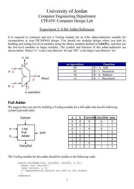
<strong>University</strong> <strong>of</strong> <strong>Jordan</strong>Computer Engineering DepartmentCPE439: Computer Design Lab<strong>Experiment</strong> 2: 8-Bit <strong>Adder</strong>/<strong>Subtractor</strong>It is required to construct and test a Verilog module for an 8-<strong>bit</strong> adder/subtractor suitable forincorporation in your PIC16F84A design. You should use modular design where you start bybuilding and testing low-level modules using the library modules defined in Lib439.v, and then usethe low-level modules in larger modules. <strong>The</strong> symbol and function <strong>of</strong> this adder/subtractor areshown below. Where “C” is the Carry/Borrow’ <strong>bit</strong> and “DC” is the Digit Carry/Borrow’ <strong>bit</strong>.C, DCA82+/-8Resultm (operation)Function00 B + A Add01 B + 1 Increment10 B – A Subtract11 B – 1 DecrementB82m (operation)Full <strong>Adder</strong>We suggest that you start by building a Verilog module for a full adder that has the followingsymbol and truth table:abCarryIn1-<strong>bit</strong>Full<strong>Adder</strong>CarryOutsuma b CarryIn CarryOut sum0 0 0 0 00 0 1 0 10 1 0 0 10 1 1 1 01 0 0 0 11 0 1 1 01 1 0 1 01 1 1 1 1<strong>The</strong> Verilog module for this adder should be similar to the following code:module Full<strong>Adder</strong>(sum, CarryOut, CarryIn, a, b);output sum, CarryOut;input CarryIn, a, b;// implementation details are left to the student…endmodule1
Multiplexer<strong>The</strong>n build and test a 2-to-1 multiplexer module that has Verilog code similar to the following code:module Mux_2_to_1(Result, s, i0, i1);output Result;input s;input i0, i1;// implementation details are left to the student…endmodule8-Bit <strong>Adder</strong>/<strong>Subtractor</strong>Finally use eight full-<strong>bit</strong> adder modules and eight 2-to-1 multiplexer modules to construct your 8-<strong>bit</strong>adder/subtractor. Note that you need also to add XOR gates to implement the subtraction. Yourmodule should have Verilog code similar to the following code:module AddSub_8b(Result, C, DC, A, B, m);output [7:0] Result;output C, DC;input [7:0] A, B;input [1:0] m;// implementation details are left to the student…endmoduleReportYour report should include detailed design, Verilog code for all modules including your testmodules, and timing diagram that demonstrates the correct operation <strong>of</strong> your design given the inputshown in the following table.A B m0000 1111 1111 0000 000101 1001 0011 1001 000101 1001 0111 1111 010000 1111 1111 0000 101001 0101 0011 1001 101001 0101 1000 0000 11Estimate the maximum delay expected for your design (show your calculations).2


![Problem 1: Loop Unrolling [18 points] In this problem, we will use the ...](https://img.yumpu.com/36629594/1/184x260/problem-1-loop-unrolling-18-points-in-this-problem-we-will-use-the-.jpg?quality=85)