continuum and discontinuum modelling in tunnel engineering
continuum and discontinuum modelling in tunnel engineering
continuum and discontinuum modelling in tunnel engineering

Create successful ePaper yourself
Turn your PDF publications into a flip-book with our unique Google optimized e-Paper software.
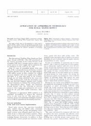
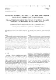
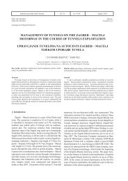
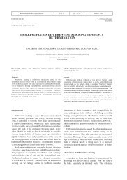
Rud.-geol.-naft. zb., Vol. 12, Zagreb, 2000.54 Burla, G., Burlu M.: Cont<strong>in</strong>uum <strong>and</strong> discont<strong>in</strong>uurn <strong>modell<strong>in</strong>g</strong>tigated by adopt<strong>in</strong>g discont<strong>in</strong>uous models, with the 2Ddist<strong>in</strong>ct element code, UDEC (I t a s c a, 1996). The rockmass surround<strong>in</strong>g the <strong>tunnel</strong>' was represented by twodiscont<strong>in</strong>uous models as follows.Figure 19. Computed ykldedwnes around the <strong>tunnel</strong> <strong>and</strong> dejormed meshus<strong>in</strong>g* elustic-brittle-phstic coastitutive model3.6.1. Determ<strong>in</strong>istic modelThe rock mass was considered to be <strong>in</strong>tercepted bythree sets of jo<strong>in</strong>ts, <strong>and</strong> foliation. Different spac<strong>in</strong>g,degree of persistence <strong>and</strong> shear strength properties were<strong>in</strong>troduced <strong>in</strong> the model so as to simulate the rock massconditions away from the fault zone as illustrated <strong>in</strong>Figure 21. The jo<strong>in</strong>ts were aga<strong>in</strong> assumed to be Mohr-Coulomb jo<strong>in</strong>ts, i.e. elasto-perfectly plastic jo<strong>in</strong>ts. Theblocks were treated as an elasto-plastic material whichfollows Mohr-Coulomb criterion. The properties of rockblocks <strong>and</strong> jo<strong>in</strong>ts are listed below:MaterialProperties(*)Zone (Figure 8 <strong>and</strong> 10)Em .tGPa]The analyses were carried out with the same assumptionsgiven above for the material <strong>and</strong> jo<strong>in</strong>t properties vm [-I<strong>and</strong> the <strong>in</strong> situ state of stress. The results obta<strong>in</strong>ed aregiven <strong>in</strong> Figure 20 by show<strong>in</strong>g the plot of the yielded c [MPalzones around the <strong>tunnel</strong> <strong>and</strong> the deformed mesh.4 r7(*> c = cohesion: &I = friction angle: E, = rock mass\ I ? 0 " , .adeformation modulus; v, = Poisson's ratio.Jo<strong>in</strong>tProperties(*)1K,, [GPa/ml 40Ks [GPa/ml 4c [MPa] 0.1+ r"l 33Jo<strong>in</strong>tZone (Figure 8 <strong>and</strong> 10) (Figure 8<strong>and</strong> 10)(*) K,,, K, = normal <strong>and</strong> shear stiffness; c = jo<strong>in</strong>tcohesion; $ = jo<strong>in</strong>t friction angle.Figure 20. Compufedyieldedzone.s uround the <strong>tunnel</strong> <strong>and</strong> deformed meshus<strong>in</strong>g the elastic-hriftle-plasli con.$titutive model for two po,~siblegeologicul condilionv along the <strong>tunnel</strong> aris3.6. Dis<strong>cont<strong>in</strong>uum</strong> <strong>modell<strong>in</strong>g</strong>With the underst<strong>and</strong><strong>in</strong>g that discont<strong>in</strong>uities (majordiscont<strong>in</strong>uities <strong>and</strong> jo<strong>in</strong>t<strong>in</strong>g) play a key role <strong>in</strong> the developmentof <strong>tunnel</strong> <strong>in</strong>stability, the problem was also <strong>in</strong>ves-3.6.2. Discrete Feature Nefwork (DFN) modelA Discrete Feature Network model was also createdby us<strong>in</strong>g the procedures implemented <strong>in</strong> the FracMancode (Dershowitz et al.. 1995). The results ofgeologic mapp<strong>in</strong>g on the right wall of ihe <strong>tunnel</strong> formedthe basis for def<strong>in</strong><strong>in</strong>g; the <strong>in</strong>put data <strong>in</strong> terms of orientation,size <strong>and</strong> degree-of fractur<strong>in</strong>g for the io<strong>in</strong>t sets J1.52<strong>and</strong> ~3 a, b. The& were superim~osed wiih foliation <strong>and</strong>discrete features represented by the two sub-paralleldiscont<strong>in</strong>uities described above. The 3D volume realized<strong>in</strong> this way is shown <strong>in</strong> Figure 22, where also shown is theplot of the jo<strong>in</strong>t sets given with the FracMan code.The UDEC model was obta<strong>in</strong>ed by tak<strong>in</strong>g a crosssection orthogonal to the <strong>tunnel</strong> axis through the 3DD m volume of Figure 22. This network of 2D fracturesis not directly amenable to UDEC analysis as the fratturesneed to be well connected <strong>and</strong> no isolated fracturescan be h<strong>and</strong>led by the code. At the same time, it wasnecessary to cross-validate the model aga<strong>in</strong>st the rockmass conditions around the <strong>tunnel</strong>. This was carried outby <strong>in</strong>creas<strong>in</strong>g the block size <strong>in</strong> the orig<strong>in</strong>al 2D networkmodel both at the crown <strong>and</strong> on the left wall, to account