continuum and discontinuum modelling in tunnel engineering
continuum and discontinuum modelling in tunnel engineering
continuum and discontinuum modelling in tunnel engineering

Create successful ePaper yourself
Turn your PDF publications into a flip-book with our unique Google optimized e-Paper software.
Rudarsko-geolaqko-naftni zbornikVol. 12str. 45-57Zagreb, 2000.1CONTINUUM AND DISCONTINUUM MODELLINGIN TUNNEL ENGINEERINGGiovanni BARLA, Marco BARLADepf. of'Struclurul und Geotechnical Eng<strong>in</strong>eer<strong>in</strong>g Politecnico di Tor<strong>in</strong>o, Corso Ducu deglr Abruur 24, Tonno, ItalyE-mail: gburlu @polroc.poli~o. itKey-words: Tunnel eng<strong>in</strong>eer<strong>in</strong>g, Cont<strong>in</strong>uum <strong>and</strong> dis<strong>cont<strong>in</strong>uum</strong> modelmg,TBM <strong>tunnel</strong>Thc paper discusses <strong>cont<strong>in</strong>uum</strong> <strong>and</strong> dis<strong>cont<strong>in</strong>uum</strong> <strong>modell<strong>in</strong>g</strong> <strong>in</strong><strong>tunnel</strong> eng<strong>in</strong>eer<strong>in</strong>g. A bricf rcview of fundamentals is presented <strong>in</strong>connection with the use of closed - formsolutions <strong>and</strong> computer bascdmethods. A few remarks are derived on the choice of either<strong>cont<strong>in</strong>uum</strong> or dis<strong>cont<strong>in</strong>uum</strong> <strong>modell<strong>in</strong>g</strong> of rock mass behaviour at thedesign analysis stage. Consideration is given to the validation of dis<strong>cont<strong>in</strong>uum</strong><strong>modell<strong>in</strong>g</strong> <strong>in</strong> connection with rock mass classification methods<strong>and</strong> cxpected <strong>tunnel</strong> response to excavation. A wse study of aTBM <strong>tunnel</strong> (4.75 m diameter) <strong>in</strong> quartzitic micaschists is discussed <strong>in</strong>detail by pay<strong>in</strong>g attention to a comparison of <strong>modell<strong>in</strong>g</strong> methods -<strong>in</strong>clud<strong>in</strong>g <strong>cont<strong>in</strong>uum</strong> <strong>and</strong> dis<strong>cont<strong>in</strong>uum</strong> model<strong>in</strong>g - applied at a faultzone.1. IntroductionThe prediction of the rock mass response to the excavationof a <strong>tunnel</strong> is a complex eng<strong>in</strong>eer<strong>in</strong>g problem. The<strong>in</strong>terest of the Rock Eng<strong>in</strong>eer at the design stage is to assessthe stability conditions of the excavation <strong>in</strong> the "<strong>in</strong>tr<strong>in</strong>sicstate" (i.e. when no support/stabilization measures are <strong>in</strong>stalled)<strong>and</strong> follow<strong>in</strong>g the adoption of suitable methods of<strong>tunnel</strong> excavation/construction <strong>and</strong> support. The key to thesuccess of such a process is the level of underst<strong>and</strong><strong>in</strong>gachieved <strong>in</strong> describ<strong>in</strong>g the rock mass conditions (<strong>in</strong> termsof geological, geotechnical, <strong>in</strong> situ stress, <strong>and</strong> hydrogeologicalparameters) <strong>and</strong> the ability to account for the fundamentalcomponents of rock mass behaviour, by us<strong>in</strong>gappropriate methods for the analysis of stresses <strong>and</strong> displacements<strong>in</strong> the rock mass around the <strong>tunnel</strong> <strong>and</strong> <strong>in</strong> thestructural components (pre-supportlpre-stabilizationmeasures; primary <strong>and</strong> f<strong>in</strong>al support, etc.).Anumber of methods are available for the stress analysisof <strong>tunnel</strong>s, from the earliest closed-form solutions to themost recent numerical <strong>modell<strong>in</strong>g</strong> methods. With the computationalpower today available at a reasonable cost, it ispossible to solve <strong>in</strong>creas<strong>in</strong>gly sophisticated problems. Inparticular, with the advent of numerical methods, we haveassisted to the development of techniques which have beenconceived to model realistically the rock mass behaviour.This is a quite different condition from the early start ofRock Mechanics, when the methods of analysis <strong>and</strong> thesolutions used were mostly taken from other eng<strong>in</strong>eer<strong>in</strong>gdiscipl<strong>in</strong>es. This is certa<strong>in</strong>ly the case of the 1898 Kirschsolution for the stresses <strong>and</strong> displacements around a circularhole <strong>in</strong> a biaxially loaded, homogeneous, isotropic <strong>and</strong>l<strong>in</strong>earlv elastic date.Closed-for6 solutions are still of great value for aconceptual underst<strong>and</strong><strong>in</strong>g of the response of <strong>tunnel</strong>s toexcavation. One could mention <strong>in</strong> this regard the solutlonswhich are presently available for the analysis of theprogressive development of failure around a circular<strong>tunnel</strong> <strong>in</strong> a hydrostatic stress field see for example:Brown et al., 1983; Panet, 1 4 95), <strong>and</strong> for theanalysis of the <strong>in</strong>teraction between the rock mass <strong>and</strong> thesupport. However, the development of modern tech-* Scientific Sym osium Rock Mechanic; <strong>and</strong> Tunnell<strong>in</strong>g, 30.9.-2.10. 1999. Zagreb, RdatiaKljufne rijeti: Tunelsko <strong>in</strong>icnjerstvo, Modelirane kont<strong>in</strong>uteta idiskont<strong>in</strong>uitcta, TBM tunelU Elanku je raspravljeno modeliranjc kont<strong>in</strong>uiteta i diskont<strong>in</strong>uitetau tunelskom <strong>in</strong>ienjerstvu. Saieto su opisane osnove zajedno s uporabommatematizkih rjeienja i raEunalnih numeriEkih metoda. Raspravljenje izbor modela kont<strong>in</strong>uurna i diskont<strong>in</strong>uuma stjenske maseu odnosu na analizu konstrukcije podgradivanja. U obzir je uzetopohrdivanje modela diskont<strong>in</strong>uiteta povezanog s metodama Masifikacijestjenskih masa i dkivane reakcije tunela pri iskopu. U detaljimaje raspravljen primjer studije TBM tunela (promjera 4,75 m) u kvarcititnimmikaSistirna, s posebnom pozornosti na usporedivanje metodamodelirania - ukliutuiuCi modeliranie kont<strong>in</strong>uuma i diskont<strong>in</strong>uurna- uporabfienih u iasjednoj zoni.niques of <strong>tunnel</strong> excavation <strong>and</strong> construction (i.e. thecase of pre-supportlpre-stabilization measures, the frequentadoption of pre-treatment ahead of the head<strong>in</strong>g<strong>in</strong> weak rock masses, the excavation sequences, typicalof large <strong>tunnel</strong>s), ... <strong>and</strong> even the complexity of rockmassconditions <strong>and</strong> behaviour, which are better describedtoday than <strong>in</strong> the past, given the modern <strong>in</strong>vestigationtools available, etc. make these solutions of limited valuefor design purposes.If we restrict our attention to modern numerical <strong>modell<strong>in</strong>g</strong>methods <strong>and</strong> rigorous analysis of <strong>tunnel</strong>l<strong>in</strong>g problems,the decision that the Rock Eng<strong>in</strong>eer need to makeat the design analysis stage is the choice between thefollow<strong>in</strong>g two approaches:- Equivalent <strong>cont<strong>in</strong>uum</strong> approach: the rock mass istreated as a <strong>cont<strong>in</strong>uum</strong> with equal <strong>in</strong> all directions<strong>in</strong>put data for the strength <strong>and</strong> deformability properties,which def<strong>in</strong>e a given constitutive relation for themedium: elastic, elasto-plastic, etc.- Dis<strong>cont<strong>in</strong>uum</strong> approach: the rock mass is representedas a dis<strong>cont<strong>in</strong>uum</strong> <strong>and</strong> most of the attention at thedesign stage is devoted to the characterization of therock elements, the rock jo<strong>in</strong>ts <strong>and</strong> discont<strong>in</strong>uities. The<strong>modell<strong>in</strong>g</strong> approach consists <strong>in</strong> consider<strong>in</strong>g the blockynature of the system be<strong>in</strong>g analysed. Each block may<strong>in</strong>teract with the neighbour<strong>in</strong>g blocks through thejo<strong>in</strong>ts. The <strong>in</strong>terest lies <strong>in</strong> the fact that the fundamentalpatterns of rock mass behaviour can be considered,as arbitrarily large relative displacements may takeplace at the contacts.This lecture is <strong>in</strong>tended to discuss a comparison of<strong>modell<strong>in</strong>g</strong> methods - <strong>in</strong>clud<strong>in</strong>g <strong>cont<strong>in</strong>uum</strong> <strong>and</strong> dis<strong>cont<strong>in</strong>uum</strong><strong>modell<strong>in</strong>g</strong> - applied at a fault zone <strong>in</strong> a TBM<strong>tunnel</strong>. Reference is made to a paper recently presentedat the 9'h International Congress on Rock Mechanics <strong>in</strong>Paris(Bar1a & et al., 1999).2. Fundamentals2.1. Cont<strong>in</strong>uum versus dis<strong>cont<strong>in</strong>uum</strong> <strong>modell<strong>in</strong>g</strong>2.1.1. Cont<strong>in</strong>uum <strong>modell<strong>in</strong>g</strong>The use of <strong>cont<strong>in</strong>uum</strong> <strong>modell<strong>in</strong>g</strong> <strong>in</strong> <strong>tunnel</strong> eng<strong>in</strong>eer<strong>in</strong>gmakes it essential to simulate the rock mass response to
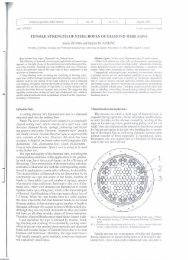
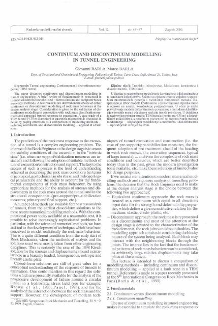
Rud.-geol.-naft. zb., Vol. 12, Zagreb, 2000.46 Uurfu, G., Burfu M.: Cont<strong>in</strong>uum <strong>and</strong> dis<strong>cont<strong>in</strong>uum</strong> <strong>modell<strong>in</strong>g</strong>excavation by <strong>in</strong>troduc<strong>in</strong>g an equivalent <strong>cont<strong>in</strong>uum</strong>. Themost common way to solve this problem, which seems toINTACT ROCKhave ga<strong>in</strong>ed wide acceptance, is to scale the <strong>in</strong>tact rockproperties down to the rock mass properties by us<strong>in</strong>gempirically def<strong>in</strong>ed relationships such as those given byHoek <strong>and</strong> Brown (1997).StrengthIf use is made of the Hoek-Brown criterion for describ<strong>in</strong>gthe rock mass behaviour, the start<strong>in</strong>g po<strong>in</strong>t ofFs = stressthe scal<strong>in</strong>g process is the def<strong>in</strong>ition of the <strong>in</strong>tact rockmaterial parameters such as oci (uniaxial compressivestrength) <strong>and</strong> mi (material constant which depends uponthe properties of the rock), which can be obta<strong>in</strong>ed based,upon the results of uniaxial <strong>and</strong> triaxial laboratory test<strong>in</strong>g.Then, by us<strong>in</strong>g well known correlations (which dependon the degree of disturbance to the rock which willvary accord<strong>in</strong>g to rock type <strong>and</strong> excavation method) withIthe most frequently adopted rock mass <strong>in</strong>dices (i.e. trun-Icated Q or RMR values, or GSI values), the rock mass >parameters such as mb <strong>and</strong> sb (rock mass constants accord<strong>in</strong>gto the Hoek-Brown criterion) or c <strong>and</strong> $ (rock 't G3mass cohesion <strong>and</strong> friction angle respectively) can beestimated (Figure 1).The next ste <strong>in</strong> the <strong>cont<strong>in</strong>uum</strong> <strong>modell<strong>in</strong>g</strong> approach isthe adoption o i' the appropriate constitutive relations for Figm I. Hoek-Brown failure criterionr for the ihtacr rock material <strong>and</strong>the rock mass. L<strong>in</strong>ear elasticity is commonly used, al-the rock mass. Ifhrtration of the scal<strong>in</strong>gprocess <strong>and</strong> dejkittionof Fuctor of Safetythounh nonl<strong>in</strong>ear elasfic constitutive eauations can alsobe adYopted. If the attention is posed or; the progressivefailure of the rock mass, the elasto-plastic models need<strong>in</strong>terior of the rock mass is represented mathematicallyto be utilized <strong>in</strong> order to describe the "post-peak" reasan <strong>in</strong>f<strong>in</strong>ite <strong>cont<strong>in</strong>uum</strong>. The doma<strong>in</strong> methods, whichsponse. A yield function which is often chosen co<strong>in</strong>cides<strong>in</strong>clude the f<strong>in</strong>ite element (FEM) <strong>and</strong> f<strong>in</strong>ite differencewith the Hoek-Brown failure criterion: (i) the rock massmethods (FDM , imply that a physical problem is modresponseis elastic, if the state of stress is with<strong>in</strong> theelled numerical 1' y by discretiz<strong>in</strong>g (i.e. divid<strong>in</strong>g <strong>in</strong>to zonesbounds def<strong>in</strong>ed by the yield function; (ii) the rock massor elements) the problem region, i.e. the rock mass <strong>in</strong>response is plastic, once the state of stress is such as towhich the excavation is to be created.reach the yield function. A number of "post-peak responsesmay be postulated depend<strong>in</strong>g upon rock massquality; the characteristics shown <strong>in</strong> Figure 2 are amongthe most frequently used for the solution of <strong>tunnel</strong>l<strong>in</strong>gproblems(Hoek <strong>and</strong> Brown, 1997):(a) Very poor quality rock mass: the rock mass behaviouris adequatelyrepresented by assum<strong>in</strong>g that it behavesperfectly plastic, which means that deformation cont<strong>in</strong>uesat a constant stress level <strong>and</strong> that no volumechange is associated with the ongo<strong>in</strong>g failure.(b) Average quality rock mass: it is reasonable to assumethat a stra<strong>in</strong>-soften<strong>in</strong>g behaviour occurs as the rockmass strength is reduced from the <strong>in</strong> situ to thebroken state; then, once this f<strong>in</strong>al, "residual" state isreached, deformation will occur at a constant stresslevel.(c) Very good quality hard rock mass: <strong>in</strong> such a case(hard rock masses, such as massive granites <strong>and</strong>gneiss) it is assumed that, when the rock massstrength is exceeded, a sudden strength dro occurs.This is associated with significant dilation o ? the rockmass, which is considered to behave as amedium withzero cohesive strength <strong>and</strong> f<strong>in</strong>ite friction angle.As summarized by Ho e k e t a 1. (1991) - also seeStartfield <strong>and</strong> Cundal (1988) - a number ofcomputer-based numerical methods have been developedover the past few decades <strong>and</strong> these provide themeans for obta<strong>in</strong><strong>in</strong>g appropriate solutons to <strong>tunnel</strong> eng<strong>in</strong>eer<strong>in</strong>gproblems <strong>in</strong> the framework of the equivalent<strong>cont<strong>in</strong>uum</strong> approach. These numerical methods can bedivided <strong>in</strong>to two classes: boundary <strong>and</strong> doma<strong>in</strong> methods.The boundary methods comprise several types of boundaryelement methods (BEM) <strong>and</strong> imply the subdivisionof the boundary of the excavation <strong>in</strong>to elements, as the2.1.2. Discont<strong>in</strong>uurn <strong>modell<strong>in</strong>g</strong>With the underst<strong>and</strong><strong>in</strong>g that rock jo<strong>in</strong>ts <strong>and</strong> discont<strong>in</strong>uities<strong>in</strong> a rock mass play a key role <strong>in</strong> the response ofa <strong>tunnel</strong> to excavation, i.e. jo<strong>in</strong>ts can create loose blocksnear the <strong>tunnel</strong> profile <strong>and</strong> cause local <strong>in</strong>stability; jo<strong>in</strong>tsweaken the rock <strong>and</strong> enlarge the displacement zonecaused by excavation; jo<strong>in</strong>ts change the water flow system<strong>in</strong> the vic<strong>in</strong>ity of the excavation (see, for example:(Shen <strong>and</strong> Barton, 1997), theuseofdis<strong>cont<strong>in</strong>uum</strong><strong>modell<strong>in</strong>g</strong> has been ga<strong>in</strong><strong>in</strong>g progressive attention <strong>in</strong> <strong>tunnel</strong>eng<strong>in</strong>eer<strong>in</strong>g ma<strong>in</strong>ly through the use of the UDEC<strong>and</strong> 3DEC codes, for 2D <strong>and</strong> 3D dis<strong>cont<strong>in</strong>uum</strong> <strong>modell<strong>in</strong>g</strong>respectively. However dis<strong>cont<strong>in</strong>uum</strong> <strong>modell<strong>in</strong>g</strong> isnot be<strong>in</strong>g used as extensively as <strong>cont<strong>in</strong>uum</strong> methods <strong>and</strong>is considered to be a relatively new <strong>and</strong> "not-yet-proven"numerical technique to ap ly for analysis <strong>and</strong> design <strong>in</strong>rock eng<strong>in</strong>eer<strong>in</strong>g projects art , 1993).In the dist<strong>in</strong>ct element method, the rock mass is representedas an assemblage of discrete blocks which maybe considered either "not deformable" or "deformable".Jo<strong>in</strong>ts <strong>and</strong> discont<strong>in</strong>uities are viewed as <strong>in</strong>terfaces betweendist<strong>in</strong>ct bodies. The important features of thismethod which make it appropriate <strong>in</strong> order to capturethe important mechanisms characteris<strong>in</strong>g a discont<strong>in</strong>uousmediumare(Cundal1<strong>and</strong> Hart, 1993): (i) themethod allows f<strong>in</strong>ite displacements detachment; (ii) themethod recognizes new contacts automatically as thecalculation progresses.In order to apply the dist<strong>in</strong>ct element method to thesolution of <strong>tunnel</strong> problems, there are two crucial issueswhich <strong>in</strong>clude the jo<strong>in</strong>t geometry data <strong>and</strong> the materialproperties assigned to the jo<strong>in</strong>ts. The first issue relatesto the <strong>in</strong>troduction <strong>in</strong> the model of those jo<strong>in</strong>ts which are
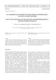
~ud.-geohaft. zb., Vol. 12, Zagreb, 2000.Barfa, G., Barla M.: Cont<strong>in</strong>uum <strong>and</strong> discont<strong>in</strong>uurn <strong>modell<strong>in</strong>g</strong> 47dc - 0'sAo't - o'r/EUS~K:AQ'I - dr/'ELASTICW N SOFTENIMPERFECTLY BR~LE> > >9 €a E4( a J w t y p 0 0 r ~ l W ~ d ~ 0)- -&mass (c) wty good quality had rod^ massFigure 2. Suggested streass-stra<strong>in</strong> laws for different quulily rock musses, note that the stress scules ure different (Hoek <strong>and</strong> Brown, 1997, modified)most critical to the response of the rock mass. Thesecond issue is closely connected with the need to assignto the jo<strong>in</strong>ts <strong>in</strong> the model the stiffness <strong>and</strong> strengthproperties of the real jo<strong>in</strong>ts <strong>in</strong> situ. Although publisheddata are readily available <strong>in</strong> the specialised literaturewhich may provide a way to guide <strong>in</strong>to the choice ofappropriate parameters (B<strong>and</strong>is, 1993), this aspect of<strong>modell<strong>in</strong>g</strong> still rema<strong>in</strong>s difficult. However, it is to beremarked that a significant help <strong>in</strong> deriv<strong>in</strong>g the necessary<strong>in</strong>put data for 2D <strong>and</strong> 3D dis<strong>cont<strong>in</strong>uum</strong> <strong>modell<strong>in</strong>g</strong> maybe obta<strong>in</strong>ed from <strong>in</strong>dex test<strong>in</strong>g of jo<strong>in</strong>ts <strong>in</strong> drill cores <strong>and</strong>from field mapp<strong>in</strong>g (B a r t o n , 1998 <strong>and</strong> 1999).2.1.3. DiscussionWhen <strong>in</strong>vestigat<strong>in</strong>g a parficular problem at the designanalysis stage the decision is to choose between <strong>cont<strong>in</strong>uum</strong><strong>and</strong> dis<strong>cont<strong>in</strong>uum</strong> <strong>modell<strong>in</strong>g</strong> of rock mass behaviour.This decision may be based on the analysis of thelikely mechanism (slid<strong>in</strong>g along jo<strong>in</strong>ts, open<strong>in</strong>g of jo<strong>in</strong>ts,Q - 0.10:twIFEMlFDY 1 DEM FEWBEMFigure 3. Schemulic diugam ,sugge.~l<strong>in</strong>g the runge of application of dis<strong>cont<strong>in</strong>uum</strong><strong>modell<strong>in</strong>g</strong> <strong>in</strong> relation to the Q-value (Bart on,1998, modified)block rotation <strong>and</strong> movement, etc.) which may <strong>in</strong>fluence<strong>tunnel</strong> stability <strong>and</strong> the jo<strong>in</strong>t spac<strong>in</strong>g relative to the sizeof the excavation. Consideration may be given to a suggestedrange of Q-values for which dis<strong>cont<strong>in</strong>uum</strong> <strong>modell<strong>in</strong>g</strong>will be more appropriate than <strong>cont<strong>in</strong>uum</strong> <strong>modell<strong>in</strong>g</strong>(Q = 0.1-100) as depicted <strong>in</strong> Figure 3 (Barton, 1998).Based upon experience ga<strong>in</strong>ed so far <strong>and</strong> a closescrut<strong>in</strong>y of design analyses which are sometimes used <strong>in</strong>*Thc senior author dcrivcs thcsc observations through cxpcricncega<strong>in</strong>ed <strong>in</strong> review<strong>in</strong>g a nurnbcr of dcsign analyses carricd out <strong>in</strong> Italy<strong>and</strong> abroad, <strong>in</strong> conncction with hydroclcctric, highways <strong>and</strong> high-spccdrailways projects.<strong>tunnel</strong> eng<strong>in</strong>eer<strong>in</strong>g (*), the follow<strong>in</strong>g observations can bederived:- Isotropic <strong>cont<strong>in</strong>uum</strong> <strong>modell<strong>in</strong>g</strong> is be<strong>in</strong>g used morefrequently than dis<strong>cont<strong>in</strong>uum</strong> <strong>modell<strong>in</strong>g</strong>, even <strong>in</strong>cases where the block size is significant, compared tothe size of excavation or the rock mass exhibits astrong anisotropic behaviour.- Numerical <strong>modell<strong>in</strong>g</strong> is be<strong>in</strong>g used too often, even <strong>in</strong>cases where problems are characterised by low levelsof both <strong>in</strong>put data <strong>and</strong> underst<strong>and</strong><strong>in</strong>g (it is appropriateto recall the classification of <strong>modell<strong>in</strong>g</strong> problemsreportedby Startfield <strong>and</strong> Cundall, 1988,whorecognize this to be the case of most rock mechanicsproblems), or the size of the planned excavation issuch as not to justify this exercise.- It appears that the easy access to computer codes,which make sophisticated methods of analysispromptly available, may result <strong>in</strong> misuse of thesemethods. Sometimes, the tendency is to be happywithhav<strong>in</strong>g run a model, even if the results obta<strong>in</strong>ed are <strong>in</strong>open contradiction with empirical design rules <strong>and</strong>cng<strong>in</strong>eer<strong>in</strong>g judgement.2.2. Validation of dis<strong>cont<strong>in</strong>uum</strong> <strong>modell<strong>in</strong>g</strong>The use of numerical <strong>modell<strong>in</strong>g</strong> <strong>in</strong> eng<strong>in</strong>eer<strong>in</strong>g practicc,connected with the need to adopt <strong>modell<strong>in</strong>g</strong>schcmes (<strong>cont<strong>in</strong>uum</strong> versus dis<strong>cont<strong>in</strong>uum</strong> <strong>modell<strong>in</strong>g</strong>)which are the most appropriate <strong>in</strong> order to analyse agivcn problem (provided that sufficient data are availahlc),po<strong>in</strong>ts out that "the <strong>modell<strong>in</strong>g</strong> of the components,rock, rock jo<strong>in</strong>ts <strong>and</strong> discont<strong>in</strong>uities is far more logical<strong>and</strong> relevant than present "black box" <strong>cont<strong>in</strong>uum</strong> models"(B art o n, 1999). The comparison shown <strong>in</strong> Figure4 well demonstrates this uo<strong>in</strong>t of view, exueciallv if criticalmechanisms of the p6ysical problem Cnder study areto be <strong>in</strong>cluded <strong>in</strong> the analysis.There is a relevant question which arises with referenceto the use of dis<strong>cont<strong>in</strong>uum</strong> <strong>modell<strong>in</strong>g</strong> <strong>in</strong> <strong>tunnel</strong>eng<strong>in</strong>eer<strong>in</strong>g <strong>and</strong> rock eng<strong>in</strong>eer<strong>in</strong>g, <strong>in</strong> general. This is <strong>in</strong>relation to the complexity of the dis<strong>cont<strong>in</strong>uum</strong> model tobe used <strong>in</strong> order to be certa<strong>in</strong> that the critical structuralfeatures have not been left out of the analysis (Hart,1993). From one side, the difficulty is <strong>in</strong> provid<strong>in</strong>g sufficientgeological data; from the other side, the computerhardware requirements may exceed that available.Based on the experience ga<strong>in</strong>ed so far, a possibleapproach to this problem consists <strong>in</strong> us<strong>in</strong>g dis<strong>cont<strong>in</strong>uum</strong>
Rud.-geol.-naft. zb., Vol. 12, Zagrcb, 2000.48 Bark, G., Barla M.: Cont<strong>in</strong>uum <strong>and</strong> dis<strong>cont<strong>in</strong>uum</strong> <strong>modell<strong>in</strong>g</strong>Figwe 5. Estimated supporf cuiegork~ hed yon the <strong>tunnel</strong>l<strong>in</strong>g qutalhty<strong>in</strong>dex Q (Grimstad <strong>and</strong> Barton, 199 )- Tunnel deformation (B a r t o n , 1998)Vertical:Horizontal: Ah =where: %<strong>and</strong> ah (the vertical <strong>and</strong> horizontal <strong>in</strong> situ stresscomponents), crc [the uniaxial compressive strength ofthe <strong>in</strong>tact rock material are given <strong>in</strong> consistent units (i.e.MPa); SPAN <strong>and</strong> HE1 b HT (the width <strong>and</strong> height of the<strong>tunnel</strong>) are given <strong>in</strong> mm.4. Comm~aon of la) <strong>cont<strong>in</strong>uum</strong> ubiuuitous iodc case <strong>and</strong> A)di~cdnt<strong>in</strong>uum ;n'dell<strong>in</strong>g results wheh analys<strong>in</strong>g typical <strong>in</strong>stabiiitymechanisms around a TBMexcavated lunnel <strong>in</strong> a weak rockmassmodelI<strong>in</strong>g <strong>in</strong> connection with rock mass classificationmethods <strong>in</strong> a framework of crossvalidation of the expected<strong>tunnel</strong> response to excavation Once the specificmodel has been proven to be awe table <strong>in</strong> a given rockmass condition, it may be improve a <strong>and</strong> furthervalidateddur<strong>in</strong>g <strong>tunnel</strong> excavation. A set of guidel<strong>in</strong>es, given as afunction of Q values, can be used as a form of prelim<strong>in</strong>aryverification of a numerical model (B art o n , 1999).-Support categoriesBased upon analyses of case records, Grim st a d <strong>and</strong>Bar ton (1993) give the diagram of Figure 5 whichallows one to relate the value of the <strong>in</strong>dex Q to thestability <strong>and</strong> support requirements of underground excavation,once the parameter which they called EquivalentDimension is obta<strong>in</strong>ed. This parameter is the span,diameter or wall height of the same excavation dividedby a numerical coefficient which is <strong>in</strong>tended to accountfor its use <strong>and</strong> the degree of security which is dem<strong>and</strong>edof the support system <strong>in</strong>stalled to ma<strong>in</strong>ta<strong>in</strong> the stabilityof the excavation.Additional guidel<strong>in</strong>es are available based on the Qsystem which allow one to assess a number of additionalparameters deal<strong>in</strong>g with <strong>tunnel</strong> stability <strong>and</strong> supportrequirements (Bart o n et al., 1974): a) the mmmumunsupported span, b) the permanent roof support pressure;c) the bolt length.2.2.1. Case ExamplesWith the case history <strong>in</strong> m<strong>in</strong>d, which is to be discussed<strong>in</strong> the follow<strong>in</strong>g, a 4.75 m diameter <strong>tunnel</strong> was taken asa typical problem to be used for validation of the discon-Figure 6. Four UDEC d e b wirh difierent Qvalucr: model 1-Q=8.5;made1 2 - Q=4.l; madel 3 - Q=1.9; model 4 - Q=0.67
~~d.-pol.-naft. zb., Vol. 12, Zagreb, WOO.Barla, G., Bark M.: Cont<strong>in</strong>uum <strong>and</strong> discont<strong>in</strong>uurn <strong>modell<strong>in</strong>g</strong>t<strong>in</strong>uurn <strong>modell<strong>in</strong>g</strong> by the 2D Dist<strong>in</strong>ct Element codeUDEC (I t a s c a, 1996). The <strong>in</strong>tent has been to <strong>in</strong>vestigatethe <strong>in</strong>fluence of rock mass conditions by the Q<strong>in</strong>dex, on the disturbed zone around the <strong>tunnel</strong>.Four models have been used as shown <strong>in</strong> Figure 6.With dimensions 20x20 m, three sets of persistent discont<strong>in</strong>uities(S, = schistosity, J1, J2 jo<strong>in</strong>ts) have been<strong>in</strong>troduced with the parameters assigned so as to obta<strong>in</strong>a range of Q values from 8.5 for model 1 to 0.67for model4. For all the models the <strong>in</strong>itial state of stress is assumedto be given by: ov (vertical stress) =16.2 MPa, oh (horizontalstress) = 4 MPa, which represent a gravity <strong>in</strong>ducedstress state at a depth of about 600 m, with anassumed stress ratio (ado,) of 0.25. The jo<strong>in</strong>t spac<strong>in</strong>g foreach system shown <strong>in</strong> Figure 6 is as follows:ModelSchistosityJOINT SPACING (m)For all the models the rock blocks are deformableblocks with the assumption that the <strong>in</strong>tact rock (gneiss)is considered as an elasto-plastic material which followsthe Mohr-Coulomb yield criterion. The properties areassigned as follows:Young's modulus E =60 GPaPoisson's ratio v=0.25Cohesionc= 30 MPaFriction angle $=33"The discont<strong>in</strong>uities are assumed to be Mohr-Coulombjo<strong>in</strong>ts, i.e. elasto-perfectly plastic jo<strong>in</strong>ts, with normal K,,<strong>and</strong> shear K, stiffness given as follows: K,, = 40 GPaIm,K, = 4 GPa/m. The cohesion is always considered to bezero, with the friction angle $ taken as 58", 38", 22' <strong>and</strong>11' respectively for models 1, 2, 3 <strong>and</strong> 4, for both theschistosity <strong>and</strong> jo<strong>in</strong>ts.- Unsupported <strong>tunnel</strong>A first series of analyses was carried out <strong>in</strong> <strong>in</strong>tr<strong>in</strong>sicconditions, i.e. the <strong>tunnel</strong> is always left unsupported,with the disturbed zone def<strong>in</strong>ed as follows (S he n a n dBarton, 1997):- failure zone, where loose rock blocks are fall<strong>in</strong>g <strong>in</strong>tothe <strong>tunnel</strong>;- open zone, where jo<strong>in</strong>ts open up;- shear zone, where jo<strong>in</strong>ts experience a certa<strong>in</strong> sheardisplacement (3 mm).The results obta<strong>in</strong>ed for the 4 models, are illustrated<strong>in</strong> Figures 7 to 9, where the failure, open <strong>and</strong> shear zonesaround the <strong>tunnel</strong> are depicted. The follow<strong>in</strong>g remarksare made: (1) the failure zones computed around the<strong>tunnel</strong> show that model 1 is stable, whereas models 2 to4 exhibit progressively critical conditions; (2) the open<strong>and</strong> shear zones appear to grow as the rock mass qualitydecreases from model 1 to 4, <strong>in</strong> l<strong>in</strong>e with the behaviour<strong>in</strong> terms of failure zones, (3) the results obta<strong>in</strong>ed seemto agree with the estimated support categories shown <strong>in</strong>Figure 5, where only the <strong>tunnel</strong> simulated with model 1would require no support, <strong>and</strong> models 2 to 4 would needdifferent <strong>and</strong> progressively more severe support measures.Figure 8. Oprm zones around the <strong>tunnel</strong> fbr models I to 4Figure 9. Shear zones around the lunnel for model9 I to 4Figure 7. Yielded <strong>and</strong> loose blocks around fhe <strong>tunnel</strong> fw modelv 1 lo 4- Supported <strong>tunnel</strong>As a direct consequence of the analyses describedabove <strong>and</strong> based upon the guidel<strong>in</strong>es of Figure 5 <strong>in</strong> termsof support requirements, the follow<strong>in</strong>g stabilizationmeasures were <strong>in</strong>troduced <strong>in</strong> models 2 to 4.
Rud.-geol.-naft. zb., Vol. 12, Zagreb, 2000.50 Burlu, G., Burlu M.: Cont<strong>in</strong>uum <strong>and</strong> dis<strong>cont<strong>in</strong>uum</strong> <strong>modell<strong>in</strong>g</strong>ElFigure 10. Pont Ventoux - Clarea F2 <strong>tunnel</strong>Model Bolts n. Bolt lenght Bolt spac<strong>in</strong>g(') Schortcrete thickness(')~olts are supposed to be <strong>in</strong>stalled accord<strong>in</strong>g to a square patternThe bolts were simulated by us<strong>in</strong>g the CABLE optionavailable with<strong>in</strong> the UDEC code, which allows one toconsider a bolt fully bonded to the rock mass. The shot-Crete was <strong>in</strong>troduced <strong>in</strong> the model by the STRUCToption which consists <strong>in</strong> simulat<strong>in</strong>g it as a series of beamsconnected to the rock mass.As a first estimate of the predictive capability of theUDEC dis<strong>cont<strong>in</strong>uum</strong> <strong>modell<strong>in</strong>g</strong> of the supported <strong>tunnel</strong>the attention is posed on compar<strong>in</strong>g the verfical <strong>and</strong>horizontal displacements Av <strong>and</strong> Ah given by the empiricalQ based formulae reported above <strong>and</strong> the results ofUDEC computations:Model233. Case studyAv [mm]Ah [mm]estimated-computed estimated-computed4.5- 5.0 2.6- 2.69.2-10.2 4.7- 5.33.1. Background <strong>in</strong>formationThe case study considers the problems occurred on 11September 1997, at ch 2360 m, when cross<strong>in</strong>g a fault zonewhich caused the TBM to become temporarily stuckdur<strong>in</strong>g excavation of the F2 <strong>tunnel</strong>, one of the majorelement of the Pont Ventoux- Susa Hydropower Project<strong>in</strong> the Susa Valley, near Tor<strong>in</strong>o. This <strong>tunnel</strong> (4.75 mdiameter) is be<strong>in</strong>g excavated by an open TBM configurationthrough uartzitic micaschists under a coverwhich is to reach 'B 00 m maximum (Figure 10).Follow<strong>in</strong>g the first 1800 m approximately where therock mass conditions where generally good, with RMRvalues rang<strong>in</strong>g from 65 to 75 (Figure ll), TBM <strong>tunnel</strong>l<strong>in</strong>g<strong>in</strong> the F2 <strong>tunnel</strong> became progressively more severewith the approach<strong>in</strong>g of the fault zone. At present, the<strong>tunnel</strong> is experienc<strong>in</strong>g very severe dificulties with consid-Figure 1 I. A view of the F2 <strong>tunnel</strong> <strong>in</strong> the section where the gneiss rockmuss was generally gooderable delays with respect to the expected advance rate.Figure 12 shows two photographs taken follow<strong>in</strong>g cha<strong>in</strong>age2360 m, where the fault of <strong>in</strong>terest <strong>in</strong> this papercrossed the <strong>tunnel</strong>, affect<strong>in</strong>g progress significantly.3.2. Description of the overstress problem at ch 2360 mThe sketch shown <strong>in</strong> Figure 13 gives a simplified illustrationof the conditions at the <strong>tunnel</strong> face where theTBM became temporarily stuck as a consequence ofoverstress<strong>in</strong>g <strong>and</strong> a 25 cm block movement of the rightsidewall (Figure 14). The quartzitic micaschist is chara~terized by the presence of three to four jo<strong>in</strong>t systems<strong>in</strong>clud<strong>in</strong>g foliation. Based on geologic mapp<strong>in</strong>g, whichwas carried out by the contractor's geologist (Pont Ventoux,1997) once the TBM could drill a few meters aheadof the section where it jammed (Figure 15), at least twosub-parallel discont<strong>in</strong>uities could be evidenced, the secondof which (a fault with stnke N66E <strong>and</strong> dip 83 to theS, which <strong>in</strong>tercepts the <strong>tunnel</strong> axis) has a clay fill<strong>in</strong>g <strong>and</strong>gouge with aperture rang<strong>in</strong>g from a few centimeters tomore than a decimeter.The rock mass conditions were estimated on a 7 rn<strong>tunnel</strong> length, from ch 2349 to ch 2356 m, with RMR<strong>in</strong>dex equal to 31. Accord<strong>in</strong>g to a more complete Q-logg<strong>in</strong>gestimate due to Barton (1997), from ch 2350 to ch
Rud.-Seol.-naft. zb., Vol. 12, Zagreb, 2000.G., Barlu M.: Cont<strong>in</strong>uum <strong>and</strong> dis<strong>cont<strong>in</strong>uum</strong> <strong>modell<strong>in</strong>g</strong> 51-ure 12. A view of flu F2 <strong>tunnel</strong>: (a) lef! (b) right walls, where stability conditions became very difiull so us to require cont<strong>in</strong>uos placement of l<strong>in</strong>er" plalerFigure 13. Skelch of the rock corulitwns a1 rltr JitceFigure 15. Rock mass conditions on the <strong>tunnel</strong> (a) left (b) rig& walls. Thepholograph was taken when the TBM was moved aheadFigure 14. Phologruph show<strong>in</strong>g the heau OJ TBM jammed wilh rockoverstress<strong>in</strong>g <strong>and</strong> block movement of the right .stdewaII2360 m, an extreme range of Q-values of about 0.007("exceptionally poor" - locally) to 0.3 ("poor") showed aweighted mean of all record<strong>in</strong>gs of about 0.05. Water isflow<strong>in</strong>g through the jo<strong>in</strong>ts at a temperature of 20'. Noquantitative data have been recorded of the water pressure,which seems unlikely to be exceed<strong>in</strong>g, with anoverburden of 650 m, a maximum of 6 to 7 MPa (outsidethe <strong>tunnel</strong> dra<strong>in</strong>age area).3.3. Rock mass strengthThe rock mass strength <strong>in</strong> the section of <strong>in</strong>terest islargely controlled by the generally "poor" conditions <strong>and</strong>the limited shear strength along discont<strong>in</strong>uities. Typicalstrength properties derived from triaxial test<strong>in</strong>g of rocksampIes are as follows:
Rud.-gco1.-naft. zb., Vol. 12, Zagreb, 2000.52 Rarlu, G., Barla M.: Cont<strong>in</strong>uum <strong>and</strong> dis<strong>cont<strong>in</strong>uum</strong> <strong>modell<strong>in</strong>g</strong>m., r[-I6.1where o~,~ <strong>and</strong> a o,, are the uniaxial compressivestrength values (peak <strong>and</strong> residual) <strong>and</strong> mipp <strong>and</strong> mi,, arethe correspond<strong>in</strong>g Hoek-Brown empirical constants.For very good quality rock masses, which is the casefor a significant <strong>tunnel</strong> length (Figure ll), typical rockmass properties can be def<strong>in</strong>ed on the basis of the GeologicalStrength Index (GSI) as follows:Intact rock strengthoCi = 144 MPaHoek-Brown constant m, =7.0Geological Strength Index GSI = 70Hoek-Brown constant mb =2.4Hoek-Brown constant s =0.02Rock mass compressive strength o,,= 27.2 MPaDeformation modulus E, =35 GPa3.4. In situ stress conditionsIn view of the high overburden <strong>and</strong> closer valley side,associated with evidence of deformation <strong>and</strong> th<strong>in</strong> slabb<strong>in</strong>g<strong>in</strong> isolated sections along the <strong>tunnel</strong> length, it wasrecommended that stress measurements by means of flat-jack tests <strong>and</strong> hydraulic m<strong>in</strong>ifracture tests be carriedout. At present only the flat-jack test data are available Gas follows, derived from measurements around the sec- -r=02 /tion of the <strong>tunnel</strong> at ch 950 m, where the overburden isapproximately 400 m:Figure 16. (a) Mmum pr<strong>in</strong>crpul .!tre.r\ contours. (6) Computed <strong>and</strong>meusured tangential strrsse.s Fht-jack slot tests, wtth overbur-Angle with respect toJack presyureden of 400 m approximatelyFlat-jack slot horizontal axisPI[MPalvalues of oCi <strong>and</strong> s = 1. The stability of the <strong>tunnel</strong> wasMI 0 34.8 assessed by computation of the strength factor contoursas shown <strong>in</strong> Figure 17. The implication is that the rockM2 +50 3.3mass <strong>in</strong>side the unit strength factor contour (SF(m,ol = 1)M3 -45 23.5 will be unstable, unless well reta<strong>in</strong>ed.Based on a stress concentration study <strong>in</strong> l<strong>in</strong>early elas-the above simplifiedtic conditions around the <strong>tunnel</strong> us<strong>in</strong>g the f<strong>in</strong>ite element l<strong>in</strong>early elastic costitutive model, no <strong>in</strong>fluence of hy-method <strong>and</strong> the phase2 code cur ab<strong>and</strong> c ku *, drostatic head considered, etc.) the <strong>tunnel</strong> experi-1997), as shown <strong>in</strong> ~i~~~~ 1 , the <strong>in</strong>itial stresses <strong>in</strong> the ences localized failure at the sidewalls which deepensplane perpendicular to the <strong>tunnel</strong> axis were evaluated to <strong>in</strong>side the rock mass as the micaschist <strong>in</strong>tact rockbe as follows: uniaxial compressive strength decreases from 100MPa to 75 MPa. This would signify that <strong>in</strong> the highlyol = maximum pr<strong>in</strong>cipal stress =13 MPaanisotropic stress regime of the <strong>tunnel</strong>, as evidencedo3 = m<strong>in</strong>imum pr<strong>in</strong>cipal stress = 2.6 MPawith a I?, value equal to 0.2, localized slabb<strong>in</strong>g <strong>in</strong>sta-O1 = angle of ol with respect to the vertical axis =15O bility cannot be ruled out, if the rock strength is <strong>in</strong> therange 100-75 MPa.3.5. Cont<strong>in</strong>uum <strong>modell<strong>in</strong>g</strong>3.5.1. The m = 0 approachIn order to determ<strong>in</strong>e to what extent the adoption ofa <strong>cont<strong>in</strong>uum</strong> <strong>modell<strong>in</strong>g</strong> approach can provide a reasonable<strong>in</strong>terpretation of <strong>tunnel</strong> <strong>in</strong>stability, numerical analyseswere first carried out to assess the stability conditionsby us<strong>in</strong>g a constant deviatoric stress criterion as proposedby (M a r t i n et a 1. (1997).The <strong>in</strong>itial stresses o, <strong>and</strong> 03 at the cross section of<strong>in</strong>terest (ch 2360 m) were assumed to be proportionallyhigher <strong>in</strong> relation to the higher overburden of 650 m.Also, the stress ratio (q,) of the m<strong>in</strong>imum stress tomaximum stress (03/01) <strong>in</strong> the plane of the <strong>tunnel</strong> crosssection was considered equal to 0.2, as <strong>in</strong> the section ofthe flat-jack measurements.The m = 0 analyses were performed by us<strong>in</strong>g thephases2 code <strong>and</strong> the Hoek-Brown criterion for different3.5.2. The elastic-brittle-plastic modelThe analyses above considered overstress<strong>in</strong>g of therockmass around the <strong>tunnel</strong> periphery, without account<strong>in</strong>gfor the presence of discont<strong>in</strong>uities. Therefore, it wasdecided to analyse the same <strong>in</strong>stability problem by <strong>in</strong>troduc<strong>in</strong>gthese features <strong>in</strong> the numerical model.As shown <strong>in</strong> Figure 18, the model comprises twoparallel discont<strong>in</strong>uities near the right sidewall, dipp<strong>in</strong>gtoward the <strong>tunnel</strong>. In order to account for the rock massdisturbance due to jo<strong>in</strong>t<strong>in</strong>g <strong>in</strong> the proximity of the discont<strong>in</strong>uities<strong>and</strong> the apparently more massive rock onthe left sidewall, where relatively little slabb<strong>in</strong>g <strong>and</strong> overstress<strong>in</strong>gwas present, it was decided to <strong>in</strong>troduce threedifferent regions <strong>in</strong> the model with the follow<strong>in</strong>g materialproperties, accord<strong>in</strong>g to the Hoek-Brown failurecriterion:
~ud.-geohaft. zb., Vol. 12, Zagreb, 2000.Barla, G., Barla M.: Cont<strong>in</strong>uum <strong>and</strong> discont<strong>in</strong>uurn <strong>modell<strong>in</strong>g</strong> 53Material properties Region (Fibwrc 18) Jo<strong>in</strong>t propcrtics Jo<strong>in</strong>t (Figurc 19)Em [GPalvm [-Ioci [MPalm, 1-12 17.5 12500.35 125150 0.080.74 01.00for: Gci = <strong>in</strong>tact rock strength; mb , mbr, sb, Sr = Hoek-Brown constants; Em = rock mass cleformation modulus;Vm = Poisson's ratio.The rock mass surround<strong>in</strong>g the <strong>tunnel</strong> was specifiedas plastic <strong>and</strong> the elastic-brittle-plastic option of phase2was activated b specify<strong>in</strong>g the constants for peakstrength (mb , S$ different than residual strength (mb,sr) only for tie more massive rock mass conditions. Thevalues were chosen on the basis of personal judgementwith the purpose to account for the better rock massconditions on the sidewall. The discont<strong>in</strong>uities were <strong>in</strong>troduced<strong>in</strong> the model by us<strong>in</strong>g the jo<strong>in</strong>t option of phase2,with the follow<strong>in</strong>g jo<strong>in</strong>t properties:for: K,, K, = normal <strong>and</strong> shear stiffness; h = jo<strong>in</strong>t0.001 aperture; c = jo<strong>in</strong>t cohesion; + = jo<strong>in</strong>t friction angle.Figure 18. Defuil ofthe FEM model near fhe funnel show<strong>in</strong>g regions wifhdifferent material propetties ad joidv (refer to vulues <strong>in</strong> previousfables)Figure 19 shows the deepen<strong>in</strong>g of the failure zones <strong>in</strong>the right <strong>and</strong> left walls as predicted by the elastic-brittleplasticmodel. The results of such an analysis is the moresignificant deepen<strong>in</strong>g of breakout on the right wall <strong>in</strong>agreement with observations <strong>in</strong> the <strong>tunnel</strong> where stressfailure <strong>and</strong> block movement actually occurred dur<strong>in</strong>gface advance, result<strong>in</strong>g <strong>in</strong> jamm<strong>in</strong>g of the TBM.It is conduded that the structural discont<strong>in</strong>uities nearthe <strong>tunnel</strong> govern to a significant extent the stabilityconditions. This is a very relevant aspect comb<strong>in</strong>ed withthe high overburden <strong>and</strong> highly anisotropic stress regime<strong>in</strong> the resent situation, <strong>and</strong> eftect of water, which wasnot <strong>in</strong>c 7 uded <strong>in</strong> the numerical analysis.o,, = 75 MPaFigure 17. Strength factor conlours determ<strong>in</strong>ed with the m = 0 upproachfor the funnel at ch 2360 m (on.=IOO, 75 MPu).3.5.3. Lessons learnedThe future geological <strong>and</strong> hydrogeological conditionsalong the <strong>tunnel</strong> alignment anticipate the presence of clayfilled discont<strong>in</strong>uities with unfavorable orientation as experienced<strong>in</strong> the actual situation, with high hydrostatic head.Then, the lessons learned so far need to be taken <strong>in</strong>toaccount <strong>in</strong> order to carefully assess the <strong>in</strong>teractive behaviourbetween the rock surround <strong>and</strong> TBM. In fact, the<strong>tunnel</strong>l<strong>in</strong>g conditions could become more problematic,as they <strong>in</strong>volve already highly stressed rock masses, withthe overburden expected to rise up to 800 m maximum.With this <strong>in</strong> m<strong>in</strong>d, also consider<strong>in</strong>g that the TBM isdriven along a curved axis, it is of <strong>in</strong>terest to use thepredictive capability of the elastic-brittle-plastic modelto analyse two possible scenarios:1) the discont<strong>in</strong>uities run parallel to the <strong>tunnel</strong> axis, atthe crown;2) the discont<strong>in</strong>uities are at the left wall.
Rud.-geol.-naft. zb., Vol. 12, Zagreb, 2000.54 Burla, G., Burlu M.: Cont<strong>in</strong>uum <strong>and</strong> discont<strong>in</strong>uurn <strong>modell<strong>in</strong>g</strong>tigated by adopt<strong>in</strong>g discont<strong>in</strong>uous models, with the 2Ddist<strong>in</strong>ct element code, UDEC (I t a s c a, 1996). The rockmass surround<strong>in</strong>g the <strong>tunnel</strong>' was represented by twodiscont<strong>in</strong>uous models as follows.Figure 19. Computed ykldedwnes around the <strong>tunnel</strong> <strong>and</strong> dejormed meshus<strong>in</strong>g* elustic-brittle-phstic coastitutive model3.6.1. Determ<strong>in</strong>istic modelThe rock mass was considered to be <strong>in</strong>tercepted bythree sets of jo<strong>in</strong>ts, <strong>and</strong> foliation. Different spac<strong>in</strong>g,degree of persistence <strong>and</strong> shear strength properties were<strong>in</strong>troduced <strong>in</strong> the model so as to simulate the rock massconditions away from the fault zone as illustrated <strong>in</strong>Figure 21. The jo<strong>in</strong>ts were aga<strong>in</strong> assumed to be Mohr-Coulomb jo<strong>in</strong>ts, i.e. elasto-perfectly plastic jo<strong>in</strong>ts. Theblocks were treated as an elasto-plastic material whichfollows Mohr-Coulomb criterion. The properties of rockblocks <strong>and</strong> jo<strong>in</strong>ts are listed below:MaterialProperties(*)Zone (Figure 8 <strong>and</strong> 10)Em .tGPa]The analyses were carried out with the same assumptionsgiven above for the material <strong>and</strong> jo<strong>in</strong>t properties vm [-I<strong>and</strong> the <strong>in</strong> situ state of stress. The results obta<strong>in</strong>ed aregiven <strong>in</strong> Figure 20 by show<strong>in</strong>g the plot of the yielded c [MPalzones around the <strong>tunnel</strong> <strong>and</strong> the deformed mesh.4 r7(*> c = cohesion: &I = friction angle: E, = rock mass\ I ? 0 " , .adeformation modulus; v, = Poisson's ratio.Jo<strong>in</strong>tProperties(*)1K,, [GPa/ml 40Ks [GPa/ml 4c [MPa] 0.1+ r"l 33Jo<strong>in</strong>tZone (Figure 8 <strong>and</strong> 10) (Figure 8<strong>and</strong> 10)(*) K,,, K, = normal <strong>and</strong> shear stiffness; c = jo<strong>in</strong>tcohesion; $ = jo<strong>in</strong>t friction angle.Figure 20. Compufedyieldedzone.s uround the <strong>tunnel</strong> <strong>and</strong> deformed meshus<strong>in</strong>g the elastic-hriftle-plasli con.$titutive model for two po,~siblegeologicul condilionv along the <strong>tunnel</strong> aris3.6. Dis<strong>cont<strong>in</strong>uum</strong> <strong>modell<strong>in</strong>g</strong>With the underst<strong>and</strong><strong>in</strong>g that discont<strong>in</strong>uities (majordiscont<strong>in</strong>uities <strong>and</strong> jo<strong>in</strong>t<strong>in</strong>g) play a key role <strong>in</strong> the developmentof <strong>tunnel</strong> <strong>in</strong>stability, the problem was also <strong>in</strong>ves-3.6.2. Discrete Feature Nefwork (DFN) modelA Discrete Feature Network model was also createdby us<strong>in</strong>g the procedures implemented <strong>in</strong> the FracMancode (Dershowitz et al.. 1995). The results ofgeologic mapp<strong>in</strong>g on the right wall of ihe <strong>tunnel</strong> formedthe basis for def<strong>in</strong><strong>in</strong>g; the <strong>in</strong>put data <strong>in</strong> terms of orientation,size <strong>and</strong> degree-of fractur<strong>in</strong>g for the io<strong>in</strong>t sets J1.52<strong>and</strong> ~3 a, b. The& were superim~osed wiih foliation <strong>and</strong>discrete features represented by the two sub-paralleldiscont<strong>in</strong>uities described above. The 3D volume realized<strong>in</strong> this way is shown <strong>in</strong> Figure 22, where also shown is theplot of the jo<strong>in</strong>t sets given with the FracMan code.The UDEC model was obta<strong>in</strong>ed by tak<strong>in</strong>g a crosssection orthogonal to the <strong>tunnel</strong> axis through the 3DD m volume of Figure 22. This network of 2D fracturesis not directly amenable to UDEC analysis as the fratturesneed to be well connected <strong>and</strong> no isolated fracturescan be h<strong>and</strong>led by the code. At the same time, it wasnecessary to cross-validate the model aga<strong>in</strong>st the rockmass conditions around the <strong>tunnel</strong>. This was carried outby <strong>in</strong>creas<strong>in</strong>g the block size <strong>in</strong> the orig<strong>in</strong>al 2D networkmodel both at the crown <strong>and</strong> on the left wall, to account
~"d.-geol.-naft. zb., Vol. 12, Zagreb, 2000.Barla, G., Barla M.: Cont<strong>in</strong>uum <strong>and</strong> dis<strong>cont<strong>in</strong>uum</strong> <strong>modell<strong>in</strong>g</strong> 55Figure 21. Detail of UDEC &termhistic model show<strong>in</strong>g regi~n,~ withdifferent material <strong>and</strong> jo<strong>in</strong>t properiiesfor the generally better rock mass conditions <strong>in</strong> thesezones.A r<strong>and</strong>om process which cancels the fracture tracesexceed<strong>in</strong>g a given limit-length fixed was used <strong>in</strong> conjunctionwith the Set edge comm<strong>and</strong> which is available withthe UDEC code. A typical model f<strong>in</strong>ally developed isshown <strong>in</strong> Figure 23. As for the determ<strong>in</strong>istic modeldescribed above, the jo<strong>in</strong>ts were assumed to behave asMohr-Coulomb jo<strong>in</strong>ts <strong>and</strong> the blocks were treated as anelasto-plastic material. The <strong>in</strong>put data are the same aslisted above <strong>and</strong> shown <strong>in</strong> Figure 21.TUNNEL FACEFigure 22.30 Dkcrete Feature Network model created by the Frac-Mancode with plot ofjo<strong>in</strong>t sets. This is typical for rock conditions onfhe rigk wall3.6.3. ResultsFor both the determ<strong>in</strong>istic <strong>and</strong> DFN models the samestress conditions as assumed for the <strong>cont<strong>in</strong>uum</strong> modelsWere applied.Figure 23. Detail of UDEC-DFN model show<strong>in</strong>g regions with differentmaterid properlies <strong>and</strong> jo<strong>in</strong>tsIn order to <strong>in</strong>vestigate whether the <strong>cont<strong>in</strong>uum</strong> approachcan yield similar results to the dis<strong>cont<strong>in</strong>uum</strong> approach, thecalculations were carried to simulate <strong>tunnel</strong> excavation asfor the f<strong>in</strong>ite element models by us<strong>in</strong>g stress boundaryconditions. Also, no account was taken for the water pressuredistributed around the <strong>tunnel</strong>. The ma<strong>in</strong> <strong>in</strong>terest wasposed on the yield zones, as shown by blocks which arefail<strong>in</strong>g, <strong>and</strong> on shear displacements <strong>in</strong>duced along jo<strong>in</strong>ts(Figure 24). Attention was also paid to the pattern of blockmovements at the right wall (Figure 25).The results obta<strong>in</strong>ed show that both the determ<strong>in</strong>istic<strong>and</strong> DFN models capture well the overstress<strong>in</strong>g conditions<strong>and</strong> block movements of right wall. As for theelastic-brittle-plastic model which accounts for the presenceof the two sub- arallel discont<strong>in</strong>uities, the deepen<strong>in</strong>gof breakout on t l!e right wall is well reproduced withthe dis<strong>cont<strong>in</strong>uum</strong> approach (compare Figure 19 withFigure 24). However, <strong>in</strong> the latter case (Figure 24) nosignificant <strong>in</strong>stability is seen to develop at the left wall,unlike the <strong>cont<strong>in</strong>uum</strong> approach (Figure 19). The similarityis evident with the actual conditions <strong>in</strong> the <strong>tunnel</strong>,where the TBM jammed because of <strong>in</strong>stability <strong>and</strong> blockmovement at the right wall (Figures 14 <strong>and</strong> 15).The <strong>cont<strong>in</strong>uum</strong> ap roach appears to capture some ofthe adverse factors w E ich were significant <strong>in</strong> the <strong>in</strong>stabilityconditions that developed dur<strong>in</strong>g TBM excavation:- the elastic-plastic-brittle behaviour of rock material,- the highly anisotropic stress regime with a very lowstress ratio,- the presence of unfavourable dom<strong>in</strong>ant discont<strong>in</strong>uitiesat the right wall.In comparison, the dis<strong>cont<strong>in</strong>uum</strong> approach shows <strong>in</strong> aremarkable manner the block movement develop<strong>in</strong>g onthe right wall, whereas the <strong>tunnel</strong> rema<strong>in</strong>s stable alongthe periphery away from the fault zone at the crown <strong>and</strong>right wall.4. ConclusionsModern numerical <strong>modell<strong>in</strong>g</strong> methods by the use ofeither the equivalent <strong>cont<strong>in</strong>uum</strong> or dis<strong>cont<strong>in</strong>uum</strong> approachhave been discussed by underly<strong>in</strong>g some of the fundamentalconcepts <strong>and</strong> guidel<strong>in</strong>es, when <strong>in</strong>vestigat<strong>in</strong>g <strong>tunnel</strong>problems at the design analysis stage. With reference to<strong>modell<strong>in</strong>g</strong> <strong>in</strong> eng<strong>in</strong>eer<strong>in</strong>g practice, the <strong>in</strong>terest has been
Rud.-geol.-naft. zb., Vol. 12, Zagreb, 2000.56 Barla, G., Barla M.: Cont<strong>in</strong>uum <strong>and</strong> dis<strong>cont<strong>in</strong>uum</strong> <strong>modell<strong>in</strong>g</strong>%I(a) iFigure 24. YeIded blocks undsheardi.splacements along the jo<strong>in</strong>& aroundthe <strong>tunnel</strong>; (a) determmisfic model, (b) DFN modelplaced on the adoption of dis<strong>cont<strong>in</strong>uum</strong> models whichgive a far more realistic <strong>and</strong> representative picture ofrock mass behaviour than equivalent <strong>cont<strong>in</strong>uum</strong> models.Modell<strong>in</strong>g of rock mass around a 4.75 m diameter<strong>tunnel</strong> excavated by an open TBM configuration throughquartzitic michaschists has been described, with attentionpaid to the <strong>in</strong>stability conditions that developedwhen cross<strong>in</strong>g through a fault zone. The calculationswere performed by us<strong>in</strong>g the f<strong>in</strong>ite element method <strong>and</strong>the dist<strong>in</strong>ct element method, accord<strong>in</strong>g to a two dimensional<strong>modell<strong>in</strong>g</strong> format, three-dimensional representationbe<strong>in</strong>g too limited <strong>and</strong> not justifiable <strong>in</strong> respectof the uncerta<strong>in</strong>ties of the <strong>in</strong>put data.With the f<strong>in</strong>ite element method an equivalent <strong>cont<strong>in</strong>uum</strong>approach was applied, <strong>in</strong>clud<strong>in</strong>g the <strong>in</strong>fluence oftwo major discont<strong>in</strong>uities on the right wall. With thedist<strong>in</strong>ct element method a fully di<strong>cont<strong>in</strong>uum</strong> approachwas used by either a determ<strong>in</strong>istic or discrete featurenetwork model. The dis<strong>cont<strong>in</strong>uum</strong> representation of therock mass captures <strong>in</strong> a remarkable manner the <strong>in</strong>stabilityconditions that developed at the TBM head dur<strong>in</strong>gexcavation. In comparison, the <strong>cont<strong>in</strong>uum</strong> representationgives a more idealised illustration of the <strong>in</strong>stability.It is concluded that for stability analysis peculiargeologic conditions such as fault zones around the <strong>tunnel</strong>require specific models, which reflect the given conditions<strong>in</strong> the most realistic way possible.Received: 2000-05-24Accepted: 2000-09-21Figure 25. Block movemertls around the funnel, (a) determ<strong>in</strong>istic model,(6) DFN d lREFERENCESBarla, G., M. Barla, L. Repetto (1999): Cont<strong>in</strong>uug <strong>and</strong>dis<strong>cont<strong>in</strong>uum</strong> <strong>modell<strong>in</strong>g</strong> for design analysis of <strong>tunnel</strong>s. 9 . Int.Coner. on Rock Mech. Paris. France.B<strong>and</strong> is ,"s . (1993): ~n~<strong>in</strong>eer<strong>in</strong>e properties <strong>and</strong> characterization ofrock discont<strong>in</strong>uities. Com~rehenslve Rock Ene<strong>in</strong>ee~e. Volume1. Fundamentals ~udsoi J.A, editor). pp. 153-183. PergamonPre~s, Oxford (U Ii ).Barton , N ., R . ' ~ e.n i , J . L u n d e (1974): Eng<strong>in</strong>eer<strong>in</strong>g classificationof jo<strong>in</strong>ted rock maqses for the design of <strong>tunnel</strong> supportRock Mechanics. Vol. 6, pp.189-236.Bart on, N. (1997): Pont Ventoux Hydropower Project. TunnelF2-Poet Ventoux. Assessment of geological condilwns <strong>and</strong>suppofifor ch 2350-dWO Report to Nocon. 25 October;%gdBarton, N. (1998): Quantitative description of rock mawes for thedesign of NMT re<strong>in</strong>forcement Spec~al Lecture 1). Int. Conf. onHydro Power Development In h imalayas. Shimla, IndiaBart on, N. 61999): General report concern<strong>in</strong>g some 2Dth centurylessons an 21S'century challenges <strong>in</strong> ap lied rock mechanics. 9thInternational Congress on Rock ~ecianics. August 25 -28.1999, Paris.Brown, E.T., J.W. Bray, B. Ladanyi, E. Hoek 1983):Characteristic l<strong>in</strong>e calculations fur rock <strong>tunnel</strong>s. J. Geotec I, . Eng.Div. Am. Soc. Civ. Enp. 109. pp.15-39.Cundall, P. A., R. D. Hart (1993): Numerical <strong>modell<strong>in</strong>g</strong> ofdiscont<strong>in</strong>ua. Comprehensive Rock Eng<strong>in</strong>eer<strong>in</strong>g. Volume 2.Analysis <strong>and</strong> Design Methods (Hudson J.A., editor). pp. 231-261. Pergamon Press, Oxford (UK).Curran, J. H. <strong>and</strong> Corkun, B. T. (1997): phase2. 2D f<strong>in</strong>iteelcment program for calculat<strong>in</strong>g stresses <strong>and</strong> estimat<strong>in</strong>g su portaround underground excavations. Reference Manual <strong>and</strong> futorialManual. Rock Eng<strong>in</strong>eer<strong>in</strong>g Group. University of Toronto.Dershowitz, W., G. Lcc, J. Geier, P. La Po<strong>in</strong>tc,(1995):FracMan Interactivc Discrcte Feature Data Analysis,
Rud.-geol.-naft. zb., Vol. 12, Zagreb, 2000.~~rlrr, G, Barlu M.: Cont<strong>in</strong>uum <strong>and</strong> discont<strong>in</strong>uurn <strong>modell<strong>in</strong>g</strong> 57Geometric Modell<strong>in</strong>g <strong>and</strong> Exploration Simulation. User docu- di derivuione nel tratto Pont Ventoux - F2 (Dott. Geol. G.mentation. Version 2.50. Seattle. Golder A.s.wciates Inc.Ventur<strong>in</strong>i).G rims t ad , E ., N . B a r to n (1993): Updat<strong>in</strong>g the Q-system for She n , B ., N . Barton (1997): The disturbed zone around <strong>tunnel</strong>sNMT. Proc. of Int. Symp. on Sprayed Concrete. Modern use of <strong>in</strong> jo<strong>in</strong>ted rock masses. lnf. J. Rock Mech. M<strong>in</strong>. Sci. Vol. 34, pp.wet mix sprayed concrete for underground sup orf. Fagernes 117-125.me om pan, 0pS.m <strong>and</strong> erg, editors). ~onvcgian LnCretc Asso- St art f i e 1 d , A. M ., C u n d a l 1 P . A. (1988): Towards a methciation.Oslo.odology for rock mechanics <strong>modell<strong>in</strong>g</strong>. Inf. J. Rock Mech. M<strong>in</strong>.art , R . D . (lF3): +n <strong>in</strong>troduction to dist<strong>in</strong>ct etement <strong>modell<strong>in</strong>g</strong> Sci. Vol. 25, pp. 99- 106.for rock engmeenng. Comprehensive Rock Eng<strong>in</strong>eer<strong>in</strong>g. Volume2. Analysis <strong>and</strong> Design Methods Hudson J.A., editor). pp. 6. Acknowledgements245-263. Pergamon Press, Oxford (U k ).Hock, E., M. W ., Grab<strong>in</strong>sky, M. S. Dicdcrichs (1991): The work described <strong>in</strong> this paper was carried out withNumerical <strong>modell<strong>in</strong>g</strong> for underground excavation design: Trurw. the f<strong>in</strong>ancial support of the [talian M<strong>in</strong>istry for Univer-Imt. M<strong>in</strong>. hfebl. VollOO. January-April1991, PP. A22-A30. sity <strong>and</strong> Technological Research (M.U.R.S.T.) as part ofHoe k, E, E., T.B ro w n (1997): Practical estimates of rock massstrength. Inl. J. Rock Mech. Mn Sci. Vol. 34, pp.1156- 1186. the R~~~~~~. programme tnnne~<strong>in</strong>g <strong>in</strong> difficult condi-Itasca Consult<strong>in</strong>g Grou (1996): UDEC (Universal Dist<strong>in</strong>ct Ele- tions" 40%). The authors would like to acknowledge thement ~ e ) version , 5.0. volume 1: user's manual. volume 11: help o G. Giampieri <strong>and</strong> L. Repetto, former students atVerification roblems <strong>and</strong> example applications. M<strong>in</strong>neapolis, the Politecnico di Tor<strong>in</strong>o.M<strong>in</strong>nesota, &A.Mart<strong>in</strong>, C. D., D. R. Mc Creath, M.The permission of AEM (Azienda Energetica Metro-Stochmal (1997):Btimat<strong>in</strong>gsu port dem<strong>and</strong>-load caused by stress-<strong>in</strong>duced failure politana) Tor<strong>in</strong>o, Owner the Pant VentOux-Susa H ~-around tunncfh. Int. Symp. on Rock Support, Lillehammer, June dropower Project, to publish this paper on the F2 <strong>tunnel</strong>1997. is gratefully acknowledged. The authors would also likepane t , M . (1995): Le calcul des <strong>tunnel</strong>s par la mCthod convergence- to thank the follow<strong>in</strong>g companies <strong>in</strong>volved <strong>in</strong> the projectcont<strong>in</strong>ement. Presses de 1'Ecole Nationale des Ponts etChau.~~.described <strong>in</strong> the paper: ~ ~ ~ s.~.A., ~ l~~~l~d <strong>and</strong> i N ~ ~p o n t V e n t o u x (1997): Nota relativa al sopralluogo effettuato <strong>in</strong>data 8/10/1997 In corrispondenza del fronte di scavo della galleria