Rud.-geol.-naft. zb., Vol. 12, Zagrcb, 2000.48 Bark, G., Barla M.: Cont<strong>in</strong>uum <strong>and</strong> dis<strong>cont<strong>in</strong>uum</strong> <strong>modell<strong>in</strong>g</strong>Figwe 5. Estimated supporf cuiegork~ hed yon the <strong>tunnel</strong>l<strong>in</strong>g qutalhty<strong>in</strong>dex Q (Grimstad <strong>and</strong> Barton, 199 )- Tunnel deformation (B a r t o n , 1998)Vertical:Horizontal: Ah =where: %<strong>and</strong> ah (the vertical <strong>and</strong> horizontal <strong>in</strong> situ stresscomponents), crc [the uniaxial compressive strength ofthe <strong>in</strong>tact rock material are given <strong>in</strong> consistent units (i.e.MPa); SPAN <strong>and</strong> HE1 b HT (the width <strong>and</strong> height of the<strong>tunnel</strong>) are given <strong>in</strong> mm.4. Comm~aon of la) <strong>cont<strong>in</strong>uum</strong> ubiuuitous iodc case <strong>and</strong> A)di~cdnt<strong>in</strong>uum ;n'dell<strong>in</strong>g results wheh analys<strong>in</strong>g typical <strong>in</strong>stabiiitymechanisms around a TBMexcavated lunnel <strong>in</strong> a weak rockmassmodelI<strong>in</strong>g <strong>in</strong> connection with rock mass classificationmethods <strong>in</strong> a framework of crossvalidation of the expected<strong>tunnel</strong> response to excavation Once the specificmodel has been proven to be awe table <strong>in</strong> a given rockmass condition, it may be improve a <strong>and</strong> furthervalidateddur<strong>in</strong>g <strong>tunnel</strong> excavation. A set of guidel<strong>in</strong>es, given as afunction of Q values, can be used as a form of prelim<strong>in</strong>aryverification of a numerical model (B art o n , 1999).-Support categoriesBased upon analyses of case records, Grim st a d <strong>and</strong>Bar ton (1993) give the diagram of Figure 5 whichallows one to relate the value of the <strong>in</strong>dex Q to thestability <strong>and</strong> support requirements of underground excavation,once the parameter which they called EquivalentDimension is obta<strong>in</strong>ed. This parameter is the span,diameter or wall height of the same excavation dividedby a numerical coefficient which is <strong>in</strong>tended to accountfor its use <strong>and</strong> the degree of security which is dem<strong>and</strong>edof the support system <strong>in</strong>stalled to ma<strong>in</strong>ta<strong>in</strong> the stabilityof the excavation.Additional guidel<strong>in</strong>es are available based on the Qsystem which allow one to assess a number of additionalparameters deal<strong>in</strong>g with <strong>tunnel</strong> stability <strong>and</strong> supportrequirements (Bart o n et al., 1974): a) the mmmumunsupported span, b) the permanent roof support pressure;c) the bolt length.2.2.1. Case ExamplesWith the case history <strong>in</strong> m<strong>in</strong>d, which is to be discussed<strong>in</strong> the follow<strong>in</strong>g, a 4.75 m diameter <strong>tunnel</strong> was taken asa typical problem to be used for validation of the discon-Figure 6. Four UDEC d e b wirh difierent Qvalucr: model 1-Q=8.5;made1 2 - Q=4.l; madel 3 - Q=1.9; model 4 - Q=0.67
~~d.-pol.-naft. zb., Vol. 12, Zagreb, WOO.Barla, G., Bark M.: Cont<strong>in</strong>uum <strong>and</strong> discont<strong>in</strong>uurn <strong>modell<strong>in</strong>g</strong>t<strong>in</strong>uurn <strong>modell<strong>in</strong>g</strong> by the 2D Dist<strong>in</strong>ct Element codeUDEC (I t a s c a, 1996). The <strong>in</strong>tent has been to <strong>in</strong>vestigatethe <strong>in</strong>fluence of rock mass conditions by the Q<strong>in</strong>dex, on the disturbed zone around the <strong>tunnel</strong>.Four models have been used as shown <strong>in</strong> Figure 6.With dimensions 20x20 m, three sets of persistent discont<strong>in</strong>uities(S, = schistosity, J1, J2 jo<strong>in</strong>ts) have been<strong>in</strong>troduced with the parameters assigned so as to obta<strong>in</strong>a range of Q values from 8.5 for model 1 to 0.67for model4. For all the models the <strong>in</strong>itial state of stress is assumedto be given by: ov (vertical stress) =16.2 MPa, oh (horizontalstress) = 4 MPa, which represent a gravity <strong>in</strong>ducedstress state at a depth of about 600 m, with anassumed stress ratio (ado,) of 0.25. The jo<strong>in</strong>t spac<strong>in</strong>g foreach system shown <strong>in</strong> Figure 6 is as follows:ModelSchistosityJOINT SPACING (m)For all the models the rock blocks are deformableblocks with the assumption that the <strong>in</strong>tact rock (gneiss)is considered as an elasto-plastic material which followsthe Mohr-Coulomb yield criterion. The properties areassigned as follows:Young's modulus E =60 GPaPoisson's ratio v=0.25Cohesionc= 30 MPaFriction angle $=33"The discont<strong>in</strong>uities are assumed to be Mohr-Coulombjo<strong>in</strong>ts, i.e. elasto-perfectly plastic jo<strong>in</strong>ts, with normal K,,<strong>and</strong> shear K, stiffness given as follows: K,, = 40 GPaIm,K, = 4 GPa/m. The cohesion is always considered to bezero, with the friction angle $ taken as 58", 38", 22' <strong>and</strong>11' respectively for models 1, 2, 3 <strong>and</strong> 4, for both theschistosity <strong>and</strong> jo<strong>in</strong>ts.- Unsupported <strong>tunnel</strong>A first series of analyses was carried out <strong>in</strong> <strong>in</strong>tr<strong>in</strong>sicconditions, i.e. the <strong>tunnel</strong> is always left unsupported,with the disturbed zone def<strong>in</strong>ed as follows (S he n a n dBarton, 1997):- failure zone, where loose rock blocks are fall<strong>in</strong>g <strong>in</strong>tothe <strong>tunnel</strong>;- open zone, where jo<strong>in</strong>ts open up;- shear zone, where jo<strong>in</strong>ts experience a certa<strong>in</strong> sheardisplacement (3 mm).The results obta<strong>in</strong>ed for the 4 models, are illustrated<strong>in</strong> Figures 7 to 9, where the failure, open <strong>and</strong> shear zonesaround the <strong>tunnel</strong> are depicted. The follow<strong>in</strong>g remarksare made: (1) the failure zones computed around the<strong>tunnel</strong> show that model 1 is stable, whereas models 2 to4 exhibit progressively critical conditions; (2) the open<strong>and</strong> shear zones appear to grow as the rock mass qualitydecreases from model 1 to 4, <strong>in</strong> l<strong>in</strong>e with the behaviour<strong>in</strong> terms of failure zones, (3) the results obta<strong>in</strong>ed seemto agree with the estimated support categories shown <strong>in</strong>Figure 5, where only the <strong>tunnel</strong> simulated with model 1would require no support, <strong>and</strong> models 2 to 4 would needdifferent <strong>and</strong> progressively more severe support measures.Figure 8. Oprm zones around the <strong>tunnel</strong> fbr models I to 4Figure 9. Shear zones around the lunnel for model9 I to 4Figure 7. Yielded <strong>and</strong> loose blocks around fhe <strong>tunnel</strong> fw modelv 1 lo 4- Supported <strong>tunnel</strong>As a direct consequence of the analyses describedabove <strong>and</strong> based upon the guidel<strong>in</strong>es of Figure 5 <strong>in</strong> termsof support requirements, the follow<strong>in</strong>g stabilizationmeasures were <strong>in</strong>troduced <strong>in</strong> models 2 to 4.
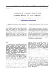
- Page 1 and 2: Rudarsko-geolaqko-naftni zbornikVol
- Page 3: ~ud.-geohaft. zb., Vol. 12, Zagreb,
- Page 7 and 8: Rud.-Seol.-naft. zb., Vol. 12, Zagr
- Page 9 and 10: ~ud.-geohaft. zb., Vol. 12, Zagreb,
- Page 11 and 12: ~"d.-geol.-naft. zb., Vol. 12, Zagr
- Page 13: Rud.-geol.-naft. zb., Vol. 12, Zagr