Design guide for metal and nonmetal tailings disposal.
Design guide for metal and nonmetal tailings disposal.
Design guide for metal and nonmetal tailings disposal.
- No tags were found...

Create successful ePaper yourself
Turn your PDF publications into a flip-book with our unique Google optimized e-Paper software.
In<strong>for</strong>mation Circular 8755<strong>Design</strong> Guide <strong>for</strong> Metal <strong>and</strong> Non<strong>metal</strong>Tailings DisposalBy Roy L. Soderberg <strong>and</strong> Richard A. BuschUNITED STATES DEPARTMENT OF THE INTERIORCecil D. Andrus, SecretaryBUREAU OF MINES
As the Nation's principal conservation agency, the Department of the Interimhos responsibility fu most of our nationally owned public l<strong>and</strong>s ond naturalresources. This includes fostering the wisest use of our l<strong>and</strong> <strong>and</strong> water resources,protecting our fish <strong>and</strong> wildlife, preserving the environmental <strong>and</strong>cultural values of our national pork <strong>and</strong> histmica1 places, <strong>and</strong> pviding fathe enjoyment of life through outdou recreation. The Deprtment assessesour energy <strong>and</strong> mineral resources <strong>and</strong> works to assure that their development isin the best interests of all our people. The Department also has a major responsibilityfa American Indian reservation communities <strong>and</strong> fa people wholive in Isl<strong>and</strong> Territaies under US. administration.This publication has been cataloged as follows:Soderberg, Roy L<strong>Design</strong> <strong>guide</strong> fm <strong>metal</strong> <strong>and</strong> non<strong>metal</strong> <strong>tailings</strong> <strong>disposal</strong> /by Roy L. Soderberg <strong>and</strong> Richard A. Busch. [Washington] :United States Depstment of the Interim, Bureau of Mines,1977.136 p. ; 27 cm. (In<strong>for</strong>mation circular - Bureau of Mines ; 8755)Bibliography: p. 107-111.1. Tailings (Metallurgy). 2. Mineral industries - Wasre dis-posal. I. Busch, Richard k., joint author. 11. United Stares.Bureau of Mincs. UI. Title. IV. Series: United States. Bureauof Mincs. In<strong>for</strong>mation circular - Bureau of Mines ; 8755.TN23.U71 no. 8755 622.06173U.S. Depr. of the Inr. LibraryFor sale bp tbc Svpcriotcodcnt of DocumeoL1. U S Gwuoment prioting OMrrWuhington. D.C. 20402St& No. 024-001-0191)-8
CONTENTSAbstract ..................................................................Introduction .............................................................Aclcnowledgments ..........................................................Background in<strong>for</strong>mation ...................................................Tailings ponds ......................................................Function of <strong>tailings</strong> ponds ..........................................Basic considerations .....................................................Daily tonnage .......................................................Size of <strong>tailings</strong> area ...............................................Mill <strong>tailings</strong> .......................................................Particle sizes ......................................................Mine waste ..........................................................Leach dmps .........................................................Site selection ...........................................................Soils <strong>and</strong> construction material investigations ......................Topography <strong>and</strong> geology ..............................................Climate <strong>and</strong> hydrology ...............................................Evaporation .........................................................Runoff ..............................................................Subsurface exploration ...................................................Logging test holes ..................................................Sampling ............................................................Laboratory testing ..................................................Grain-size distribution ........................................Specific gravity <strong>and</strong>.void ratlo ................................Relative density ................................................Plasticity .....................................................Compaction .....................................................Shear strength ....:............................................Permeability ...................................................Consolidation tests ............................................Field testing ......................................;................St<strong>and</strong>ard penetration ...........................................Density ........................................................Shear strength .................................................Permeability ...................................................<strong>Design</strong> criteria ..........................................................Upstream method .....................................................Downstream method ...................................................Centerline method ...................................................Upstream method with cyclones .......................................Starter dam design ..................................................Pervious starter dam ...........................................Impervious starter dam .........................................Drainage ............................................................Drains ..............................................................Blanket drain ..................................................Pipe drain ...................................................... ~. \
~ ~~-CONTENTS .-ContinuedStrip drain ....................................................Filters <strong>and</strong> transition zones ...................................Relief wells ...................................................Vertical s<strong>and</strong> drains ...........................................Rate of seepage ................................................Surface runoff control ..............................................Initial construction ...................................................... .Site preparation ....................................................Water reclaim system ................................................Decant pipe <strong>and</strong> towers .........................................Barge pumps ....................................................Siphons ........................................................Comparison of the three systems ................................. Decant system ................................................Barge pump system .........................................Siphon reclaim system ....................................Starter dam construction ............................................Fill compaction .....................................................Construction durtng operation .............................................Coarse s<strong>and</strong> <strong>and</strong> clean separation by spigoting .......................Fine grind <strong>and</strong> poor separation by spigoting .........................S<strong>and</strong> yield ..........................................................Upstream construction with spigot s<strong>and</strong> ..............................Upstream construction with cyclones .................................Downstream construction wlth cyclones ...............................Centerline method ...................................................Influences on design ................................................S<strong>and</strong> separation .....................................................spigots ........................................................Cyclones .......................................................Pond water management ...............................................Embankment freeboard <strong>and</strong> wave protection ............................Cores, blankets, <strong>and</strong> membranes ...........................................Sealing the bottom of <strong>tailings</strong> ponds ................................Hydraulic barriers ..................................................Instrumentation ..........................................................Piezometers .........................................................Movement indicators .................................................Pressure cells ......................................................Records .............................................................Slope stability ..........................................................Safety factor .......................................................Rotational slides ...................................................Computer allalysis ...................................................Computer input ......................................................Maintenance <strong>and</strong> inspection ...............................................Seepage control in an operating pond ................................Surface drainage control ............................................
iiiRemedial measures ...................................................Surmnary ..................................................................Bibliography .............................................................Appendix B.--Estimating runoff ...........................................Appendix C.--Seepage <strong>and</strong> flow nets .......................................Appendix D.--Slope stability analysis, simplified - . ..........~ Bishop methodAppendix E.--Nomenclature ................................................Appendix A.--Tailings pond evaporation ...................................Capacity-elevation-the curve .......................................Screen analysis-- typical <strong>metal</strong> mine general mill <strong>tailings</strong> ...........Gradation of typical Florida phosphate slimes .......................Increased density with depth ........................................Typical log of exploration hole .....................................Key <strong>for</strong> exploration logs ............................................Mohr diagram ........................................................Permeability coefficients <strong>for</strong> soils .................................Gradation of <strong>metal</strong> mine <strong>tailings</strong>-- coarse grind. low pulp density,mine A ............................................................Gradation of <strong>metal</strong> mine <strong>tailings</strong>-- fine grind. high pulp density.mine B ............................................................Downstream method showing both dams .................................Blanket drain .......................................................Pipe drain ..........................................................Pipe drain layout ...................................................Transitions <strong>and</strong> filters protecting drains ...........................Screen analysis of four filter materials ............................Decant tower with 6-inch outlets at 4-112 inches center-to-center ...Decant line to tower 6-xnch outlets at each 6-inch elevation rise ...Steel-rein<strong>for</strong>ced decant lines--4 2-inch ID ...........................Schematic of decant, barge pup. siphon. <strong>and</strong> pump with floodedintake ............................................................Barge pump <strong>and</strong> decant tower in the same pond ........................Barge pump <strong>and</strong> line-- steep terrain ..................................Barge pump <strong>and</strong> line-- iron ore mine ..................................Siphon on large <strong>tailings</strong> pond .......................................Starter dam excavation-- general plant section .......................Starter dam construction-- detail ....................................Screen of four zone materials .......................................Spigoting around periphery of dike-- upstream method .................Borrow pit after constructing dike with dragline-- upstream method ...Plan of upstream method with cyclones ...............................Upstream method with cyclones .......................................Downstream method with cyclones .....................................Cyclones on centerline method of dam building in small operation ....Barrier <strong>for</strong>med by borrow area in upstream construction ..............
ILLUSTRATIONS ..ContinuedPermeability. mine A. uni<strong>for</strong>mity of change ......................... 75Permeability, mine B. mnuni<strong>for</strong>mity of change ...................... 76Permeability, mine C. mnuni<strong>for</strong>mity of change ....................... 76Change of base permeability with time <strong>and</strong> material ................. 77Location of phreatic line <strong>for</strong> frozen versus unfrozen face .......... 77Core trench ......................................................... 80Impervious zones..cores ............................................ 80Closed system ...................................................... 81Clear water-soil contact .: ...................................... 81Five-foot slime layer at bottom of pond ............................ 82Pumping wells <strong>for</strong> hydraulic barrier <strong>and</strong> relief wells ............... 83Porous-tube piezometer installation ..... (Casagr<strong>and</strong>e type) .............. 84Pneumatic piezometer <strong>and</strong> readout ................................... 85Effect of embankment stratification on required width of...longitudinal drains in homogeneous dams .......................... 86...Zoned dam study .................................................... 87Flow nets <strong>for</strong> Kt, = & .............................................. 88Slope indicator data ............................................... 89Plan of rotational slide ........................................... 92Rotational slide ................................................... 93Circular failure arc .............................................. 95Sample of computer ariwlysis ........................................ 97Factor of safety fromphreatic water height in dam ................. 98Reducing downstream slopes ......................................... 102Surcharge on toe of slope .......................................... 102Berm <strong>and</strong> slope drainage ............................................ 103Remedial methods ................................................... 105....Mean annual class A pan evaporation ................................ 113Mean annual class A pan coefficient ................................ 114Mean annual lake evaporation ....................................... 115Unit hydrograph peak versus width .................................. li9~ ..Solar radiation versus latitude <strong>and</strong> sunshine ....................... 122-Clear sky solar radiation .......................................... 123Flow net construction ............................................ 128TABLES1 . Physical properties of <strong>tailings</strong> .................................... 72 . Sampling methods <strong>for</strong> various soil types ............................ 193 . Approximate 'relationship between st<strong>and</strong>ard penetration <strong>and</strong>relative density <strong>and</strong> consistency <strong>for</strong> cohesionless soils .......... 274 . Approximate relationship between st<strong>and</strong>ard penetration <strong>and</strong>relative density <strong>and</strong> consistency <strong>for</strong> cohesive soils .............. 275 . Compaction equipment <strong>and</strong> methods ................................... 626 . Embanbent freeboard <strong>and</strong> wave protection ........................... 78B-1 . Infiltration indices .............................................. 117
DESIGN GUIDE FOR METAL AND NONMETAL TAILINGS DISPOSALRoy L. Soderberg' <strong>and</strong> Richard A. Busch2ABSTRACTThe Bureau of Mines has conducted substantial research on the design, construction,<strong>and</strong> operation of <strong>metal</strong> <strong>and</strong> non<strong>metal</strong> <strong>tailings</strong> ponds. This design<strong>guide</strong>, like related Bureau publications :that preceded it, is produced toassist the industry in the management of mill <strong>tailings</strong> <strong>disposal</strong>. It coversthe site selection, sampling, laboratory testing, design, construction, operation,<strong>and</strong> inspection of <strong>tailings</strong> embankments. The effects of environment, Itopography, <strong>and</strong> hydrogeology are also included, <strong>and</strong> various methods of stabilityanalysis <strong>and</strong> factors affecting stability are reviewed. Because of thediversity of problems encountered in <strong>tailings</strong> embankments, specific solutionsare not intended. The <strong>guide</strong> is, however, a useful checklist <strong>for</strong> designers,operators, <strong>and</strong> inspectors of this type of structure.INTRODUCTION 'This <strong>tailings</strong> <strong>disposal</strong> design <strong>guide</strong> has been prepared by the Bureau ofMines especially <strong>for</strong> those mining engineers <strong>and</strong> Government officials responsible<strong>for</strong> the design, construction, operation, <strong>and</strong> inspection of mine <strong>tailings</strong>ponds. These design recornendations are intended to deal specifically withwaste from <strong>metal</strong> <strong>and</strong> non<strong>metal</strong> ores; however, many of the points discussed areapplicable to coal waste embankments, dry mine waste piles, leach dumps, <strong>and</strong>strip <strong>and</strong> placer operations which are not specifically covered in this report.The mining <strong>and</strong> processing of low-grade <strong>metal</strong>lic ores results in largequantities of waste which leave the plant as a slurry with a 30- to 50-percentpulp density containing as much as 30 to 80 percent material of minus 200-meshsize. This slurry is retained in the <strong>tailings</strong> ponds, allowing the solids tosettle out. The decant water may be recycled or allowed to discharge into awatercourse. Mining operations of 30,000 to 100,000 tons per day are notuncowon with 9% percent being waste which has to be stored in <strong>tailings</strong> ponds.The size of these ponds has increased tremendously in the last 10 years; <strong>for</strong>'Mining engineer.'civil engineer; associate professor of civil engineering, Gonzaga University,Spokane, Wash.Both authors are with the Spokane Mining Research Center, Bureau of Mines,Spokane, Wash.
example, in 1938, 1 ton of ore produced 27 pounds of copper; 1947--18 pounds;1960--14.4 pounds; <strong>and</strong> 1971--11 pounds. This trend will probably continue,but at a reduced rate. The <strong>disposal</strong> problem will get worse in the future aslarger tonnages are milled <strong>and</strong> l<strong>and</strong> becomes more costly. The height of thedams will have to be increased, compounding the stability problems.Research has been conducted on <strong>tailings</strong> embankments in mountainous areaswhere long winters with snow <strong>and</strong> freezing weather are major obstacles <strong>and</strong> indesert areas where the main problems are seepage into the ground water, dust,<strong>and</strong> water conservation.Previous Bureau publications have dealt with various phases of <strong>tailings</strong><strong>disposal</strong>, including design <strong>and</strong> operation, stability analysis, <strong>and</strong> seepage@-33) .3 This report presents additional in<strong>for</strong>mation on these subjects aswellTs the newest techniques <strong>for</strong> reducing seepage into the ground water <strong>and</strong><strong>for</strong> improving the stability <strong>and</strong> safety of the embankments.ACKNOWLEDGMENTSThe authors are grateful to American Smelting <strong>and</strong> Refining Co. (ASARCO)<strong>for</strong> allowing research to be conducted on various properties <strong>and</strong> <strong>for</strong> itsassistance in this work, <strong>and</strong> to other U.S. mining companies <strong>for</strong> allowingB~reau~personnel to inspect <strong>and</strong> study their operations. We are also indebtedto the following personnel of the Bureau's Spokane Mining Research Center:C. D. Kealy <strong>and</strong> M. McDonald <strong>for</strong> technical assistance on soil mechanics <strong>and</strong>computer output, <strong>and</strong> L. Atkins, R. Canes, <strong>and</strong> D. McKenzie <strong>for</strong> the laboratorytest work.BACKGROUND INFORMATIONThe prime purpose of the design <strong>guide</strong> is to outline the criteria relatingto waste <strong>disposal</strong>, some of the problems that will be encountered, <strong>and</strong> how tosolve them. The includes explicit details of site investigation, designrequirements <strong>and</strong> specifications, constructiontechniques, inspection procedures,<strong>and</strong> detailed investigations including sampling <strong>and</strong> testing to check the stabilityof present <strong>and</strong> future embankments by use of the computer. It is imperativethat the design <strong>and</strong> operation of waste sites be conducted under thedirect supervision of engineers who are competent in the fields of waste<strong>disposal</strong>, construction, soil mechanics, geology, hydrology, <strong>and</strong> hydraulics.Tailings PondsAs used in this <strong>guide</strong>, <strong>tailings</strong> ponds comprise embankments placed on theground surface that are required to retain slurries of waste <strong>and</strong> water; theyare constructed from <strong>tailings</strong>, borrow material, or some of each. Some minesuse deslimed <strong>tailings</strong> <strong>for</strong> underground fill, leaving only the finer material tobe impounded on the surface. The materials range from chemically stablequartz to unstable feldspars which can alter to micrometer-size clay.3Underlined numbers in parentheses refer to items in the bibliography precedingthe appendixes.
An adequate or satisfactory <strong>tailings</strong> embankment is defined as one thathas a good factor of safety, will retain solids, <strong>and</strong> will control the liquidwaste. Prevention of pollution by both solids <strong>and</strong> liquid must be incorporatedin the design plans, together with shapes <strong>and</strong> stable slopes that will enhancerehabilitation of the area after it has been ab<strong>and</strong>oned.Function of Tailings PondsThe main function of a mine <strong>tailings</strong> pond is to store solids permanently<strong>and</strong> to retain water temporarily. The length of time that water must beretained ranges from a few days to months, depending on gradation, mineralogy,etc. When clarified, the water can be reclaimed <strong>for</strong> plant use or dischargedinto the drainage.When the water contains a serious pollutant, the <strong>tailings</strong> dam must bedesigned to retain the water <strong>for</strong> longer periods until the harmful chemicalshave degraded or until the water evaporates. A completely closed system ispreferred in all such cases, not only <strong>for</strong> conservation,of water, but as anecessity to prevent the pollutant from being discharged. The seepage waterfrom this type of dam must be controlled, treated, <strong>and</strong> pumped back to the mill<strong>for</strong> reuse.BASIC CONSIDERATIONSEconomics continue to be of prime importance in the design of <strong>tailings</strong>embankments, including site selection, pumping requirements, length of pipeline, <strong>and</strong> capital versus operating cost. The annual tonnage versus siteacreage, physical properties of <strong>tailings</strong>, type of embankment, method of waste<strong>disposal</strong>, availability of construction materials, climate, terrain, hydrology,geology, <strong>and</strong> nature of the foundation at alternative sites are all importantfactors. The consequences of failure should be fully considered in establishingthe factor of safety (FS) of the embankment design. Embankments inseismically active areas should undergo dynamic analysis to eliminate thepossibility of liquefaction from earthquake shock. Embankments in remoteareas can have a lower FS than needed in urban areas. Operating costs <strong>for</strong><strong>tailings</strong> <strong>disposal</strong> can be a big item in a mining operation, <strong>and</strong> much thoughtshould go into the study of capital versus operating cost. In some cases, theplanwiththe cheapest capital cost canbethe most expensive when the operatingcost is added, <strong>and</strong> viceversa. Probably the cheapest operation possible wouldbe one where a few water-type dams couldbeconstructedtoenclose alarge area,allowing the operator to merely dump the tai1ings;thiswouldcompletelyeliminate operating labor except <strong>for</strong> pump operation <strong>and</strong> periodic inspections.Operation of porphyry copper, taconite, <strong>and</strong> pebble phosphate mines canmore easily anticipate the ultimate area needed <strong>for</strong> <strong>tailings</strong> <strong>disposal</strong> <strong>for</strong> thelife of the deposit than can operation of underground deep-vein mines. Thesesurface deposits are generally well defined with known ore reserves <strong>for</strong> agiven number of years. Knowing this <strong>and</strong> the anticipated daily tonnage,definite plans <strong>for</strong> a <strong>tailings</strong> <strong>disposal</strong> area can be made. Any planned expansionshould be considered at the same time, keeping approximately 35 acres per
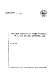
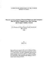
1,000 tons of mill production <strong>for</strong> <strong>metal</strong> mines, preferably in two separateareas. Taconite operations require about the same acreage per 1,000 tonsof waste ~roduced. Under special conditions, such as single-point dischargeinto large areas where cheap l<strong>and</strong> is available <strong>and</strong> other factors arefavorable, the area per 1,000 tons of waste could go up to two to three timesthis, but observation of well-engineered taconite <strong>tailings</strong> areas indicatesthat 35 acres per 1,000 tons is about optimum where discharge pipelines surroundthe area. Phosphate mines in flat terrain will require nearly an acreof settling pond per acre of mined l<strong>and</strong> until some improvement in settlingrate can be achieved. Because of the fineness of the material <strong>and</strong> the lowpulp density, it is generally deposited at a single point at a time.Size of Tailings AreaThe size of the <strong>tailings</strong> embankment necessary <strong>for</strong> each 1,000 tons ofmilling capacity <strong>for</strong> a safe <strong>and</strong> efficient operation is governed to some extentby the size of the grind, but mostly by the terrain within the <strong>tailings</strong> area.A relatively level area of a wide, open valley is an ideal site because of thelarge volume of <strong>tailings</strong> placed per foot of elevation rise. A starter damconstructed from borrow material is a very important part of the entireimpoundment. The purpose of this dam is to contain the s<strong>and</strong> <strong>and</strong> provide apond large enough to insure sufficient water clarification at the start ofoperations. The steeper the terrain within the embankment area, the higherthe starter dam must be to supply the storage necessary <strong>for</strong> the s<strong>and</strong> <strong>and</strong> wateruntil the embankment can be raised with the beach s<strong>and</strong>. It is far better tomake the starter dam a bit higher than required because of the unknown factorsat startup of an impoundment. These unknowns are (1) the efficiency of segregationof the s<strong>and</strong> <strong>and</strong> slime on the beach, (2) the angle of the beach area,<strong>and</strong> (3) most important, the retention time in the pond to get clean water. Acapacity curve plotting the volume against elevation should be made, as wellas a time-capacity curve to get the elevation rise per year through the lifeof the impoundment (fig. 1).Where the maximum annual rise is limited to less than 8 feet per year,the active <strong>disposal</strong> area must be at least 20 acres per 1,000 tons of dailycapacity. Operating at this upper limit of rise per year <strong>for</strong> continuousoperation might be safe, but this depends on the grind, pulp density, <strong>and</strong> typeof material being impounded. From an operating <strong>and</strong> safety point of view, afigure of 30 acres per 1,000 tons of daily capacity is much better <strong>for</strong> the- lower limit of a mature pond. If the site is on a hillside, the startup timeis most critical because the area of active storage is small. There is noestablished rate that an embankment can be raised, but <strong>for</strong> a given material,gradation, <strong>and</strong> pulp density there is a definite maximum rate of rise abovewhich stability becomes a problem. If the <strong>tailings</strong> cannot drain as fast asthey are placed in the pond, the phreatic surface rises <strong>and</strong> comes out the faceabove the toe dam. When this occurs, seepage <strong>and</strong> piping take place, loweringthe safety factor to the danger point. Possible solutions are to allow time<strong>for</strong> drainage <strong>and</strong> to place a filter <strong>and</strong> rock surcharge on the toe. A rapidannual rise is undesirable because the material does not have time to properlydrain, consolidate, <strong>and</strong> stabilize, nor is there time to raise the peripheraldam.
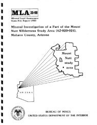
3503W--MILLION TONS10 20 30 40 50 60 70 801 I I I I I IE+cFYI2Y100500Too rapid annual rise, unstable condition,10.000 - 40.m tpd in 2 years, steep terrain 130-percentislapel2 ponds alternated,flat terrain (2. percent slopel, stable conditions,25.000 tpd, 36 acres per thous<strong>and</strong> tpd production-FIGURE 1. - Capacity-elevation-time curve.1 2 3 4 5 6 7 8 9 10 11 12CALENDAR YEARThe ~ond area reauired <strong>for</strong> clarification of the water prior to reclanationof discharge into the local drainage is difficult to determine by experimentalor theoretical means. The problem is to provide sufficient retentiontime to permit the very fine fractions to settle be<strong>for</strong>e they reach the decant.The settlement velocities of various grain sizes <strong>and</strong> shapes can be determinedtheoretically; however, several factors determine the effectiveness of settlementin the field, such as grain size, percentage of slimes, pH of the water,wave action, <strong>and</strong> depth of water.The size of grind required to liberate the <strong>metal</strong> from the waste can producea material having 55 percent or more minus 200 mesh so that the settlingrate is quite slow. Particles of 50-micrometer: size have a settlement rate of0.05 inch per second <strong>and</strong> will settle in a reasonable time even though affectedby wave action. The most difficult particles to settle are those of 2 micrometersor less; these have a theoretical settlement rate of 0.01 inch persecond in still water,but in fact may take days because of wave action.The quality of the water returned to the mill or the watershed willdetermine the retention time <strong>for</strong> any particular mine. The time required maybe as low as 2 days <strong>and</strong> as high as 10 days, with an average of about 5.Mill TailingsMetal mine <strong>tailings</strong> include materials from hard quartz to mudstone withvast differences in physical properties. Finely ground mill waste high insilica can have a high shear angle at high densities with little or nocohesion <strong>and</strong> still be very susceptible to erosion by wind <strong>and</strong> water. Materialshigh in feldspar may have a high shear strength when fresh, but canchemically change to clay with time, reducing the strength. Relatively minor
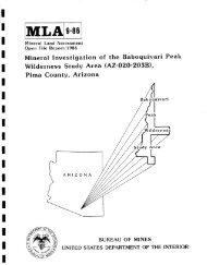
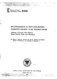
amounts of sulfide can oxidize to <strong>for</strong>m a crust <strong>and</strong> lower the pH enough thatvegetative growth is difficult or impossible without adding topsoil or alteringthe material in some way. High-sulfide <strong>tailings</strong> may ignite by spontaneouscombustion or produce acidic runoff, iron oxide, or hydroxide, which canpollute large areas in a drainage basin. The sodium cyanide from gold oretreatment plants requires a long retention time in the <strong>tailings</strong> pond, <strong>and</strong> sometimesrequires treatment with chlorine or other oxidizing agents to neutralizethe cyanide to tolerable levels ( 4.3 ppm) be<strong>for</strong>e release. The waste fromuranium mining <strong>and</strong> milling can be very dangerous <strong>for</strong> many years owing to radioactivedaughter products.Particle SizesThe grind necessary to free the <strong>metal</strong>lic minerals <strong>for</strong> flotation rangesfrom about 30 percent to 80 percent minus 200 mesh (fig. 2). S<strong>and</strong>-fillingoperations at some mines remove the coarse s<strong>and</strong>, leaving an even finer materialto be impounded in <strong>tailings</strong> ponds.Taconite plant waste products include a float product of 3/8- to 1/2-inchsize <strong>and</strong> a spiral <strong>and</strong> flotation reject containing up to 70 percent minus 325mesh, <strong>and</strong> there is a possibility of even finer grind to 90 percent minus 325mesh to reduce the silica content in the pellets. Not all plants have thesame waste products, but all could have all or part of those listed. SomeI HYDROMETER ANALYSISSCREEN ANALYSIS 1I1 US. St<strong>and</strong>ord Slew SuesI5 4 3 2 1987 6 5 4 3 2 019876 5 4 3 2 001GRAIN SIZE, rnmFIGURE 2. - Screen analysis-typical <strong>metal</strong> mine general mill <strong>tailings</strong>.
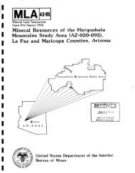
also have iron oxides or hydroxides that precipitate out of the seepage water,which must be contained within the impoundment.Pebble phosphate operations have two waste products from their washingplants--a fine, white, clean silica s<strong>and</strong> similar to ocean beach s<strong>and</strong>s, <strong>and</strong> aclay product all of which is smaller than 0.02 micrometer with 60 percentminus 0.001 micrometer (fig. 3). These two products are approximately twothirdsof the matrix as mined <strong>and</strong> milled. The clay waste product comes fromthe wash plant at 4 to 5 percent pulp density <strong>and</strong> is very slow to dewater <strong>and</strong>consolidate. For this reason it requires nearly 1 acre of pond <strong>for</strong> each acremined.Table 1 shows specific gravity (G,), the coefficient of uni<strong>for</strong>mity (C,)(Deo ID, O)r <strong>and</strong> the effective size (Dl,). of some typical <strong>tailings</strong> materials.(NOTE.--D,, is the particle size diameter (D) at "60 percent finer than" onthe gradation curve. )TABLE 1. - Physical properties of <strong>tailings</strong>MineralGold mine (s<strong>and</strong> removed <strong>for</strong> fill) .......Iron (ore) ..............................Lead.. ..................................Zinc ....................................Copper ..................................Molybdenum ..............................Florida phosphates .....................Gs2.6 - 2.74.6 - 6.02.8 - 3.42.922.71-2.752.6 -2.72.6Cu9.207.759.3870.0018.9220.0010.00qotUm2.59.08.03.04.08.0.06EQUIVALENT SPHERICAL DIAMETER,pmFIGURE 3. - Gradation of typical Florida phosphate slimes.
Hole 585 30 95 100 105 l I0DENSITY, pounds per cubic footFIGURE 4. - Increased density with depth.The fielddensity of a <strong>tailings</strong>pond increaseswith time <strong>and</strong>depth below thesurface. A typicalexample of thedensity change ina copper <strong>tailings</strong>pond that is in anarea with a highlypermeable base <strong>and</strong>where two pondsare used alternatelyis shown infigure 4. Thedensity rangesfrom 90 to 95pounds per cubicfoot at the surfaceto 100 to 105pounds per cubicfoot at the 45-foot depth. Inthis example theinactive pond isallowed to dry sothe dike can beraised <strong>for</strong> thenext 10-foot fill.These <strong>tailings</strong> aredischarged at 48+percent pulp density<strong>and</strong> contains58 percent minus200-mesh material,resulting in avery poor segregationof coarse <strong>and</strong>fine material inthe pond.The increasein density withdepth depends somewhaton the mineralogy,screen size,<strong>and</strong> specific gravity, but of more importance is the ability of the water todrain through either drains or a permeable base.
An important physical property of mill <strong>tailings</strong> is their shear strength.This property is expressed by the angle of internal friction, 4, <strong>and</strong> apparentcohesion, c. Typical values <strong>for</strong> the 4 angle are 20' to 35", increasing withincreased percentage of s<strong>and</strong> in the <strong>tailings</strong>. Apparent cohesion is the functionof mineralogy, moisture, <strong>and</strong> particle spacing; typical values range from0 to 5 psi.Mine WasteInvestigation <strong>and</strong> testing of mine waste (not <strong>tailings</strong> ponds) <strong>and</strong> mineleach dumps are generally similar to these phases of dam or highway construction.The stability of waste embankments requires the investigation of thefollowing factors <strong>for</strong> a critical analysis:1. Natural degradation of the waste materials due to time <strong>and</strong> weather,resulting in a loss of shear strength.2. Water levels in the embankments. These are especially critical inleach dumps, where millions of gallons of water are pumped into the dumps eachday, or when drainage water enters the embankment.3. Sealing of embankment exteriors by weathering.4. Incompetent material beneath the embankment such as clays, etc.To evaluate these conditions it may be necessary to--1. Research similar wastes in existing embankments.2. Drill, sample, <strong>and</strong> test <strong>for</strong> physical properties3. Instrument the embankments to monitor continuing behavior utilizing--A. Piezometers <strong>and</strong> open wells to measure water pressure.B. Slope indicator <strong>and</strong> surface monuments <strong>for</strong> de<strong>for</strong>mationmeasurements.C. Photographs that might show changes in appearance (aerial orground photos).D. Monthly or quarterly surveys <strong>for</strong> a permanent record.E. Pumping tests to estimate water volume in dumpMaterials that commonly degrade rapidly are shales, siltstones, <strong>and</strong> mudstones;the feldspars can degrade into clay. Some feldspars found in swellingporphyry are already partly decomposed <strong>and</strong> could breakdown quite rapid15 ifexcavated <strong>and</strong> exposed to the elements. Often these materials will graduallylose their strength when exposed to freezing, thawing, wetting, <strong>and</strong> drying, orto the relief of stress by excavation. If the loss of strength is substantial,
a waste pile designed based on the strength of the fresh material could becomeunstable at some time in the future. There<strong>for</strong>e, piles of waste that may besusceptible to degradation should be designed on the basis of the loweststrength that the material might attain. Accelerated tests of degradation canbe per<strong>for</strong>med in the laboratory using rapid cycles of freezing <strong>and</strong> thawing,wetting <strong>and</strong> drying, or exposure to acids such as those used in copper leachdumps that might influence the waste. These tests may not indicate the finalstrength of the material but could indicate that the waste material may changewith a reduction in strength. Borrow material may be required to confine thepile rather than relying on the material itself <strong>for</strong> stability. This materialshould always be protected so that surface drainage does not flow through itbecause of leaching of <strong>metal</strong>lic ions, degradation, stability, etc. Samples ofthe degraded material may be found in the field <strong>and</strong> would be much more nearlyrepresentative when testing <strong>for</strong> strength.Many ''waste'' embankments that have been accumulating <strong>for</strong> over 50 yearsare now being leached <strong>for</strong> the recovery of copper. No special care in placingthe material to insure stability seemed necessary because the material was dry<strong>and</strong> was to remain dry during the early stages of placement. With the adventof leaching, these vast piles of "waste" became partially saturated <strong>and</strong> stabilityproblems developed. Impervious zones at each lift allow leach solutionsto cascade out onto the face, added weight causes bulging of thefoundation material, <strong>and</strong> degradation due to wetting the material itselfresults in relatively impervious zones. These dumps can absorb billions ofgallons of water be<strong>for</strong>e a water balance is attained. Stability then becomes aproblem, <strong>and</strong> piezometeis <strong>and</strong>lor open wells <strong>for</strong> monitoring the phreatic lineare very important. Slope indicators or surface monuments should be installedto monitor movement of the embankment, <strong>and</strong> drilling <strong>and</strong> sampling should extendinto the foundation material.Leach DumpsMost U.S. leach dumps consist of waste <strong>and</strong> low-grade ore that has accumulatedfrom mines <strong>and</strong> open pits over a period of years (up to 50 years or more);this material now can be leached at a profit by simply spraying or injectingwater or dilute acid over the surface <strong>and</strong> collecting the pregnant solution <strong>for</strong>precipitation. The gradation ranges from large boulders to fine clay with acontinuing change in physical properties as the material changes with time <strong>and</strong>chemical action. Stability analyses of these embankments are very difficultto make because of the heterogeneous mixture of the materials. When low-gradeores are placed into leach dumps, all roadways <strong>and</strong> hard-packed areas should bethoroughly ripped be<strong>for</strong>e they are covered with more ore.SITE SELECTIONThe selection of a site <strong>for</strong> <strong>tailings</strong> <strong>disposal</strong> has to be made when theplant <strong>and</strong> mine sites are selected. In the feasibility study of a new property,a tentative <strong>tailings</strong> site must be picked. It should be within a radius of 10miles, preferably as close to the mill as possible, <strong>and</strong> downstream from themill <strong>for</strong> gravity flow of the <strong>tailings</strong>. It must be of adequate size to accommodatethe annual tonnage of <strong>tailings</strong> without too rapid rise in the height ofthe embankment each year.
In a new area <strong>and</strong> early in the mine exploration period (as soon as itbecomes apparent that a mine is in the making), data should be gathered in thearea. All climatic data should be gathered, <strong>and</strong> onsite measurements of streamflow <strong>and</strong> evaporation should be made. Sedimentation characteristics, turbidity,pH, <strong>metal</strong>lic ion count, etc., on the proposed waste should be determined. U.S.Geological Survey (USGS) topographical maps are usually available. Detailedcontour maps of the impoundment area are necessary <strong>for</strong> the planning <strong>and</strong> designof mine waste embankments. Aerial photographs are useful <strong>for</strong> locating geologicalfeatures that may not be discernible by surface reconnaisance <strong>and</strong> mapping<strong>and</strong> <strong>for</strong> locating potential 'sources of construction materials.The USGS maps are valuable <strong>for</strong> reconnaisance surveys, <strong>for</strong> choosing a site,<strong>for</strong> measuring area <strong>and</strong> volume, <strong>and</strong> <strong>for</strong> general geology, drainage area, creeks,etc. Major faults should be avoided in the <strong>tailings</strong> area <strong>and</strong> especially inthe dam area. By the time of site selection, there should be enough geologicalin<strong>for</strong>mation available to eliminate potential <strong>tailings</strong> sites on 9 mineralizedareas, vein extensions, potential shaft sites, pit access, or possiblepit extensions. The site should be far enough from projected mining to precludeseepage, spills, or runs into the mine through faults, shafts, or fracturesfrom mining operations.Habitation downstream from a potential <strong>tailings</strong> dam would affect thedesign in that a higher factor of safety would be necessary than in a remotearea.Soils <strong>and</strong> Construction Material InvestigationsSite investigation <strong>for</strong> low embankments of 100 feet or less on sites wherebedrock is at shallow depths can be assessed by auger holes <strong>and</strong> test pits.For plants with large daily tonnages, where l<strong>and</strong> <strong>and</strong> capital costs <strong>for</strong> <strong>tailings</strong><strong>disposal</strong> are high, design must be <strong>for</strong> large areas with up to 500-foothighembankments. This requires careful <strong>and</strong> detailed study of the foundationmaterials, especially if clays or silts are present. Extensive foundationdrilling, sampling, <strong>and</strong> testing may be necessary. Soil samples should betested <strong>for</strong> inplace density, gradation, shear strength, consolidation, <strong>and</strong>moisture content. These tests are also needed <strong>for</strong> location <strong>and</strong> availabilityof borrow material <strong>for</strong> toe dam construction.Organic soils are generally very compressible, have low shear strength,<strong>and</strong> should be removed from embankment foundations. When saturated or underload, they could act as a lubricant <strong>and</strong> cause a failure.Coarse, sound angular rock, such as talus, will be strong <strong>and</strong> pervious,but settlement can be expected if it is uncompacted. Some sedimentary rockssuch as shales <strong>and</strong> mudstones weather severely <strong>and</strong> reduce the shear strength ofthis type of fill.Solid bedrock has more than adequate compressive <strong>and</strong> shear strength tosupport mine waste impoundments. Where dams are to be constructed on or nearbedrock, surface springs or artesian water can be a danger. Faults or faultgouge can affect the stability of an embankment.
The physical properties of glacial tills <strong>and</strong> similar soil mixtures dependon their densities <strong>and</strong> gradations. The amount <strong>and</strong> type of fines are important.Water levels should be measured in all exploratory holes <strong>and</strong> test pits,especially where materials of different permeability are encountered. Artesianwater should be noted <strong>and</strong> considered in the dgsign.Pneumatic piezometers should be placed in strategic drill holes in thefoundation <strong>and</strong> carefully mapped <strong>for</strong> location <strong>and</strong> elevation to provide continuousreference during the life of the embankment.Most <strong>tailings</strong> embankments require a toe dam or starter dam. If the <strong>tailings</strong>themselves are to be used <strong>for</strong> embankment construction, the specific gravity,gradation, permeability, <strong>and</strong> shear strengths at the expected density ofthe <strong>tailings</strong> are necessary. Given the geometry, density, shear strength, <strong>and</strong>anticipated phreatic surface, a stability analysis should be run on theembanbent to check the factor of safety at its designed height, say 500 feet.If the FS is too low, additional compaction or a flatter downstream slope maybe necessary to bring the FS to a satisfactory figure.Topography <strong>and</strong> GeologyTopographic maps necessary <strong>for</strong> planning a mine waste embankment can beobtained from the USGS. These topographic maps are available in variousscales: 1:125,000 at 100-foot contour intervals; 1:62,500 at 50-foot <strong>and</strong> 40-foot intervals; 1:24,000 at 40-, 20-, <strong>and</strong> 10-foot intervals; <strong>and</strong> 1:12,000 at40-<strong>and</strong> 20-foot intervals. When an area has been chosen, more detailedtopographic mapping may have to be done locally, especially where the toe dam<strong>and</strong> drains are to be built.Aerial photos of most of the United States are available from USGS inMenlo Park, Calif. They are a help in geological mapping because faults, differenttypes of rock, ground cover, etc., are noticeable. Local detailedgeology will probably have to be done by the company building the embankmentor by a consultant hired to do this work. It is essential that this be donewell <strong>and</strong> in great detail to be sure there are no weak or incompetent soil orrock, no major faults, <strong>and</strong> no ore deposits in the imediate area.?he extent of geological investigation necessary <strong>for</strong> a <strong>tailings</strong> impoundmentwill depend on the height to which it is to be built <strong>and</strong> the complexityof the foundation material. The foundation must be firm enough to preventundue settlement, strong enough to withst<strong>and</strong> the shear stresses, <strong>and</strong> of anature that seepage can be controlled.For a major <strong>tailings</strong> impoundment a logical sequence of geological investigationshould include:1. Location <strong>and</strong> study of geological reports, maps, <strong>and</strong> photographs2. Field reconnaissance, including surveying <strong>and</strong> mapping of surfacedeposits, their extent <strong>and</strong> mode of occurrence; any outcrops, etc.
3. If overburden is deep, geophysical surveys may be necessary to determinethe depth.4. Measurement of ground water levels, which may also include pumpingtests.5. Location of all seeps <strong>and</strong> springs within the <strong>tailings</strong> area <strong>and</strong>especially in the dam area.6. Core drilling <strong>for</strong> location of faults, planes of weakness, mineralization,<strong>and</strong> ground water. The main reason <strong>for</strong> core drilling is to check <strong>for</strong>mineralization. Any other in<strong>for</strong>mation is a bonus <strong>and</strong> may be very helpful.7. Evidence of solution cavities or collapse of cover, which are commonin limestone beds.8. Evidence of sloughing along valley walls caused by water, clay seams,or weak <strong>for</strong>mations, indicating unstable conditions.The geological history of the surface deposits in <strong>and</strong> near the embankmentsite can often dictate the design <strong>and</strong> construction of the initial dam. Theorigin of the deposits <strong>and</strong> whether they have been subjected to consolidationpressures since their <strong>for</strong>mation will indicate the physical properties thatmight be expected. Highly compacted <strong>and</strong> consolidated soils which demonstrategood shear strength are generally ample foundation <strong>for</strong> an embankment. Bedrockmakes an excellent foundation, provided there are no extensive soft seams, orthe material is not soft weathered shale, mudstone, schist, etc. If the overburdenis shallow, the bedrock essentially becomes the foundation, <strong>and</strong> underthese conditions it should have more than ample strength.Climate <strong>and</strong> HydrologyWhen exploration is being carried on <strong>for</strong> a new property in relativelyremote <strong>and</strong> virgin country, hydrologic investigations should be started. TheNational Weather Service has records available <strong>for</strong> the entire United States,but if the area is remote from a weather station, site records should be madeof daily temperature, precipitation, solar radiation, wind, <strong>and</strong> evaporation.The Water Resources Division of the USGS has streamflow measurements of mostmajor streams, but here again specific minor tributary streams should be measured.Water quality of all the watersheds in the vicinity should be checked<strong>for</strong> turbidity, <strong>metal</strong>lic ions, pH, etc. The latter is especially important inthat a stream flowing from a heavily mineralized area might have a higher<strong>metal</strong>lic ion content in its natural state than is allowed in the State <strong>and</strong>Federal regulations. A 3- to 4-year history of streamflowbeside, through,or beneath a <strong>tailings</strong> impoundment is important <strong>for</strong> the designer. The probabilityof a 100-year flood, or larger, is also important.EvaporationIn the arid Southwest as much as 84 inches of water per year may be lostby evaporation from a <strong>tailings</strong> pond, <strong>and</strong> this is one of the major water losses.
Evaporation from water surface is influenced by solar radiation, wind,air temperature, <strong>and</strong> vapor pressure. Since solar radiation is an importantfactor, evaporation varies with latitude, season, time of day, <strong>and</strong> cloudcover.The National Weather Service Class A pan is used <strong>for</strong> estimating evaporationfrom lakes <strong>and</strong> reservoirs. It consists of an unpainted galvanized ironpan, 4 feet in diameter <strong>and</strong> 8 inches deep, placed on a wood frame to allow airto circulate completely around it. It is filled daily to a depth of 8 inches<strong>for</strong> 12 to 18 months, <strong>and</strong> evaporation is monitored. Additional instruments canbe installed near the evaporating pan to relate the measured evaporation inthe pan to meteorological factors. Some of these instruments are--1. Wet- <strong>and</strong> dry-bulb thermometers <strong>for</strong> air <strong>and</strong> precipitation temperatures,vapor pressure, <strong>and</strong> dew points.2. Anemometer <strong>for</strong> wind.3 . Precipitation gages--one nonrecording <strong>and</strong> one weighing-type recordinggage .-Pan coefficients (ratio of lake evaporation to pan evaporation) are used toestimate the evaporation from lakes <strong>and</strong> reservoirs. The evaporation fromnatural lakes <strong>and</strong> reservoirs is 0.6 to 0.8 as much as from the Class A pan, acoefficient of 0.7 is a good average figure.Appendix A gives further in<strong>for</strong>mation on evaporation.RunoffRunoff must be considered in designing a mine <strong>tailings</strong> pond. The annualspring runoff can best be assessed by even a few years of records <strong>for</strong> a givenwatershed. Where this in<strong>for</strong>mation is not available <strong>and</strong> the watershed is small,hydraulic h<strong>and</strong>books have simple equations to calculate runoff flow rates. TheNational Weather Service has maximum probable precipitation <strong>for</strong> a general areawhich can be used, <strong>and</strong> assuming a saturated watershed, a runoff hydrograph canbe drawn. The design must be made to h<strong>and</strong>le the 100-year flood whether it isby spillway, diversion ditch, decant tower with discharge lines, or pipebeneath the embankment.In areas of high snowfall the maximum rain could occur in the winter on adeep snow pack with above-freezing temperatures. The runoff could beincreased by melting of a large portion of the snow, so that the total runoffcould be even greater than the total rainfall.A reliable method <strong>for</strong> estimating runoff volume <strong>and</strong> flow requires threesteps. Step 1 is the estimation of the amount of precipitation in the <strong>for</strong>m ofrain or snow <strong>for</strong> a duration equal to the time of concentration <strong>for</strong> the area.This in<strong>for</strong>mation is available from the National Weather Service, as are themaximum storm <strong>and</strong> the probable frequency of occurrences. Step 2 is theassessment of the runoff losses in the catchment area by vegetation,
evaporation, infiltration, <strong>and</strong> storage in lakes, etc., all depending on thecharacteristics of the area. This step can be eliminated by being on the safeside <strong>and</strong> assuming a saturated watershed, which often happens when the mainstorm is preceded by many days of rain.Step 3 then assumes that all the precipitation is runoff <strong>and</strong> the timing<strong>and</strong> quantity of the maximum flow are the only problems. A few years' recordof precipitation <strong>and</strong> streamflow in that drainage will show the shape of thehydrograph, which should be more accurate than a synthetic streamflow hydrograph.(Synthetic hydrographs are drawn from generalized data available onpublished climatic maps <strong>and</strong> records from adjacent areas.) To obtain onsitein<strong>for</strong>mation recording <strong>and</strong> nonrecording rain gages, a snow storage gage, <strong>and</strong> arecording streamflow measurement gage are necessary. Streamflbw measurementsare also required to determine the stage-discharge relationship of the streamgage.The National Weather Service has records of precipitation, <strong>and</strong> the WaterResources Division of the USGS has streamflow records <strong>and</strong> hydrographs whichcan supply in<strong>for</strong>mation <strong>for</strong> a specific watershed not directly covered by theirstreamflow gages.SUBSURFACE EXPLORATIONTwo main goals of subsurface investigations are to find evidence of previousmining operations <strong>and</strong> to determine the possibility of future miningunder the dam area since such mines may collapse due to the additional loadingcaused by the impoundment. Caving or sublevel stoping without fill can causefracturing far from the actual mine <strong>and</strong> allow <strong>tailings</strong> from a superimposed<strong>tailings</strong> pond to run into the mine.Surface trenching <strong>and</strong> test pits are the most economical method of samplingto obtain the physical properties, quantities, <strong>and</strong> quality of materials<strong>for</strong> dam building, drainage, filters, etc. Drilling may be necessary in thedeeper overburden using such drilling equipment as a wash boring machine withcasing, churn drill, rotary drill using mud, diamond drill, hammer drill usingcasing with air, or Becker4 hammer drill without casing using air. Shelbytube samples, split-spoon samples <strong>for</strong> penetration resistance, <strong>and</strong> disturbedsamples may be obtained from the drill holes. The Becker drill delivers acontinuous disturbed sample but is limited where large hard boulders areencountered. Power augers with hollow stem <strong>and</strong> continuous flight augers allowsampling through the hollow stem without casing but are also limited to smallgravel <strong>and</strong> finer soils.If the subsoil is very competent <strong>and</strong> uni<strong>for</strong>m, a minimum amount of drillingwill be required, but if it is erratic with seap of clay, soft s<strong>and</strong>, ormany dissimilar soils, enough drilling should be done to obtain a soilprofile.4Reference to specific trade names does not imply endorsement by the Bureau ofMines.
The foundation borings should be deep enough to determine the subsoilcharacteristics within the depth affected by the structure. A competent foundationmaterial is not difficult to attain in most instances, but there areproblem areas that should be mentioned including buried talus deposits thatare very pervious, solution cavities in limestone, <strong>and</strong> soft seams in an otherwisecompetent clay. Another problem is deep overburden where nearly all theseepage goes out the bottom of the pond <strong>and</strong> not out the downstream face whereit can be reused or monitored <strong>for</strong> quality be<strong>for</strong>e going into the drainage.This will become increasingly important in the future when seepage into thegroundwater will not be tolerated. Shallow overburden with an imperviousbedrock is good because a trench can be cut into the bedrock to catch <strong>and</strong> controlthe seepage.Logging Test HolesTypical <strong>for</strong>ms <strong>for</strong> logging test hole or pit samples are shown in figure 5;figure 6 is a key <strong>for</strong> exploration logs. Different observers should try theirbest to st<strong>and</strong>ardize their interpretation bf various materials encountered <strong>and</strong>tested. Logging of samples should be done by a trained soils engineer, whoshould be on the job continuously during sampling to keep records up to date,<strong>and</strong> the logs should be prepared in final <strong>for</strong>m as soon as possible after thehole is completed. Hvorslev (28) treats this subject in considerable detail.Complete <strong>and</strong> accurate detail of the samples taken from test pits <strong>and</strong>drill holes is critical <strong>for</strong> correct analysis of an embankment site. Logsshould be kept of the elevations <strong>and</strong> thicknesses of the various strata orhorizons that are encountered. In addition, the color, structure, estimatedtextural classification, <strong>and</strong> any other identifying characteristics of the soilin each horizon should be noted. 'Ihe designation of the textural class of asoil in the field is only a temporary identification procedure which will bemodified or made permanent after the results of a laboratory analysis becomeavailable. However, the personnel of a soil survey party may become quiteproficient in estimating the textural classification by visual examination inthe field.Drilling <strong>and</strong> sampling <strong>for</strong> site investigation should also include the locationof burrow material <strong>for</strong> dam construction. Sampling should follow the samepattern as <strong>for</strong> foundations <strong>and</strong> be extensive enough to assure an ample supplyof the needed material as close to the dam site as possible.
tREMARKSmlr no#. rapr.lntrmnfin".liano' hal. MD-2_Xm
SamplingSamples are classified according to sampling procedures used: wash samples,disturbed samples, <strong>and</strong> undisturbed samples. Table 2 shows the samplingmethods <strong>for</strong> various soil types.
TABLE 2. - Sampling methods <strong>for</strong> various soil typesType of soilMethods of boring(methods shown inparentheses arerarely used)Reconnaissanceexploration, representativesamples(sampling in boringsof each significantstratum, 5-footmaximum spacing)Detailed exploration,small undisturbedsamples (sampling inborings , continuoussamples, 2- to 3-inchdiameter)Special exploration,large .undisturbedsamples (sampling inbarings of controllingstrata, 4- to6-inch diameter)Surface sampling,undisturbed samples<strong>and</strong> control samples(sampling close 'tosurface, accessibleexplorations <strong>and</strong>earth structures)Common cohesive<strong>and</strong> plasticsoils.isplacement, washauger continuoussampling (percus -sion, rotary).ugers, 1- to 2-inchpiston or open-drivesampler.>in-wall drive sampler,pen or with stationary>r free piston.hin-wall ar compositedrive sampler with freeor stationary piston(cut, wire, vacuumrelief).- to 6-inch thinwallopen-drive orfree-piston sampler,4- to 8-inch advancetrim. 8- to 12-inch-square boxsample.Slightly cohesive<strong>and</strong>brittle soilsincluding siltloose s<strong>and</strong>above groundwater.s above, but keepboring dry <strong>for</strong>undisturbed samplingabove graunmwater.hin-wall drive sampler,free or stationarypiston (vacuum relief).s above, but advancetrimming or box samplingpreferable.Very soft <strong>and</strong>sticky soils.Saturated silt<strong>and</strong> looses<strong>and</strong>.isplacement, washbailers, s<strong>and</strong>pumps, continuoussampling (auger,rotary).isplacement, washbailers, s<strong>and</strong>pumps, continuoussampling (rotary):lit or cup sampler,1- to 2-inch pistonor apen-drive sampler(core retainersused).18 above, release stationarypiston be<strong>for</strong>tany intentionaloverdriving .,in-wall drive sampler~ith stationary piston.tin-wall drive sampler,free or stationary?iston, 2-inch diameter.hin-wall or compositedrive sampler withstationary piston,vacuum relief required.hin-wall drive sampler,free or stationarypiston, vacuum relief ofreezing bottom ofsample required.- to 6-inch thinwallopen-drive orstationary pistonsampler, danger ofsoil movements <strong>and</strong>disturbance be<strong>for</strong>esampling.- to 6-inch thinwallsampler, openor free or stationarypiston, 4-to 8-inch advance,trim sample, depressground water level.Compact orstiff <strong>and</strong>brittle soilsincludingdense s<strong>and</strong>,partiallydried soils.ash, augers, percussion,rotarycontinuoussampling..ugers <strong>and</strong> 1- to 2-inch thick-wallpiston or open-drivesampler.sdium-wall open.drive or,iston sampler. Hammeringmay be required(partial disturbance).ore boring may be bettethan drive sampling, budanger of contaminationin partially dry sails.- to 8-inch advancetrim. 8- to 12-inch-square box ofblock samples.Auger core baring.Bag sample <strong>and</strong> fielddensity.G
TABLE 2. - Sampling methods <strong>for</strong> various soil types--ContinuedType of soilMethods of boring(methods shown inparentheses arerarely used)Reconnaissanceexploration, reprcsentativesamples(sampling in boringsof each significantstratum, 5-footmaximum svacing)Detailed exploration,small undisturbedsamples (sampling inborings, continuoussamples, 2- to 3-inchdiameter)Special exploration,large undisturbedsamples (sampling inborings of ?mtrollingstrata, 4- to6-inch diameter)Surface sampling,undisturbed samples<strong>and</strong> control samples(sampling close tosurface, accessibleexplorations <strong>and</strong>earth structures)Hard, highly compacted or partiallycementetsoils, no grave'or stones.ercussion, rotarycontinuoussampling.bick-wall open-drivesampler. Coreboring.hick-wall open-drive orpiston sampler. Corebaring. Small-diametersamples, often partiallydisturbed.ore boring preferable todrive sampling. Dangerof fluid contaminationin permeable sails.5- to 12-inch-squarebox samples orirregular blocksamples.Coarse gravelly<strong>and</strong> stony soilsincluding campact<strong>and</strong> coars*glacial till.ercussion barrelauger, loosen byexplosives, thickwall drivesampler.errel auger, thickwalldrive sampler(COTC retainer).lot vracticable ...........dvance freezing, thencore boring.5- to 12-inch-squarebox samples, bagsample, <strong>and</strong> fielddensity.Gaseous orexp<strong>and</strong>ing sail:(organic softclay, silt,s<strong>and</strong>).ccording to soil,but keep boringfilled with wateror drilling fluid.s above, according tmbasic soil type.hin-wall sampler withfreeor stationary piston.Force closed samplerthrough exp<strong>and</strong>ed soil.Determine original samplllength <strong>and</strong> volume. Seal.ing to prevent expansion.hin-wall sampler withfree or stationary pistonForce closed samplerthrough exp<strong>and</strong>ed sail.Determine original samplilength <strong>and</strong> volume. Sealing to prevent expansionThin-wall drive sampler,open or pistontype. Danger ofexpansion of soilbe<strong>for</strong>e sampling.Gradual or suddenchanges insoil propertie!within a singlcdrive.s above, accordin)to basic soiltype.afe length of sampleincreased when progressingfrom weak to firmstrata <strong>and</strong> vice versa.Thin soft strata, oftcndisturbed. Withdrawafter passing firmstratum.afe length of sampleincreased when progressingfrom weak to firmstrata <strong>and</strong> vice versa.Thin soft strata, oftendisturbed. Withdrawafter passing firmstratum.9s above, accordingto soil type. Whenpossible, separatecoarsc- <strong>and</strong> fincgrainedsoil.Soils withsecondarystructure.s above, according tobasic soil type, but theresults of strength, con.solidation, <strong>and</strong> permeabilitytests do notalways represent propertiesof undisturbeddeposit.s above, according tobasic sbil type, but theresults af strength, consolidation, <strong>and</strong> permeabilitytests do notalways represent propertiesof undisturbeddeposit.Large box or blocksamples. Large testspecimens. Detailfield tests <strong>and</strong>observations.
Wash samples consist of drill cuttings removed from the hole by circulatingair or water, or simply wash s<strong>and</strong> <strong>and</strong> gravel removed ahead of casingdriven into the soil or by bailing from a churn drill. The approximate stratigraphy<strong>and</strong> a preliminary soil classification can be determined from washsamples, but they are not reliable <strong>for</strong> laboratory testing or positive soilidentification.Disturbed samples are obtained in thick-walled sample tubes such as thesplit-spoon sampler <strong>and</strong> are useful <strong>for</strong> general classification tests <strong>and</strong> soilidentification as well as gradation, specific gravity, moisture content, <strong>and</strong>Atterberg limits (4-5). - - They are not suitable <strong>for</strong> strength tests.Undisturbed samples require sophisticated sampling equipment such ashollow-stem augers that require no casing, <strong>and</strong> special techniques are used topreserve the sample in its natural condition. The most cormnon sampler is theShelby tube, which is a thin-walled steel tube approximately 3 inches indiameter <strong>and</strong> 24 or 30 inches long. It should be pushed into the soil by asteady pressure such as a hydraulic ram <strong>and</strong> not be a hammering action. Itshould be sealed to prevent loss of water during h<strong>and</strong>ling <strong>and</strong> storage <strong>and</strong>should be transported in shock-proof containers. These undisturbed samplesare suitable <strong>for</strong> all laboratory tests such as triaxial <strong>and</strong> direct shear,screen size, density, moisture, specific gravity, <strong>and</strong> void ratio. The resultsof these tests will reveal many characteristics of the in situ soil deposit.Sampling from a drill hole can be comparatively simple or can require aconsiderable degree of experience <strong>and</strong> ingenuity, depending on the type ofdeposit <strong>and</strong> the degree of disturbance that is acceptable. A relatively uni<strong>for</strong>mdeposit may be sampled at 5-foot intervals, while weaker or highlyerratic zones may require continuous sampling.In cohesive soil, clay, <strong>and</strong> s<strong>and</strong> <strong>and</strong> in some gravel, the hollow-stemauger is ideal <strong>for</strong> use with a Shelby tube, piston, or split-spoon sampler. Ablow count <strong>for</strong> relative density determination can also be obtained with thesplit-spoon samples. It is impossible to get Shelby tube samples in saturateds<strong>and</strong> except with the cryogenic equipment that freeze only the tip with COz toretain the sample in the tube until it can be removed from the hole. If muchgravel is present, thick-wall drive samplers or barrel augers are used, whichrequires care <strong>and</strong> experience to obtain good samples.Hamer drills using air <strong>and</strong> percussion are frequently used in explorings<strong>and</strong>s, gravels, <strong>and</strong> even waste dumps containing coarse rock. Samples fromthis drilling are valuable as indicators of the material in the hole but arenot truly representative because of degradation <strong>and</strong> segregation of particlesin transport up the casing. The action of the drill can indicate if the materialis coarse boulders with voids or well-graded material.Laboratory TestingGrain Size DistributionThe laboratory procedures <strong>for</strong> determining grain size is described inASTM 422-63 (American Society <strong>for</strong> Testing <strong>and</strong> Materials) (3). In this procedure,the sample is divided into a coarse fraction <strong>and</strong> a fTne fraction; thecoarse material is mechanically separated on several screens <strong>and</strong> washedthrough a 200-mesh screen. The fine fraction is tested by hydrometer orSedigraph to establish its gradation.
If the soil's grain size is quite variable, a number of samples must betested to get an envelope of distribution curves to <strong>for</strong>m a basis <strong>for</strong> assessingsome of the soil's other characteristics.Specific Gravity <strong>and</strong> Void RatioThe specific gravity of soil particles is determined by laboratory testASTM D854-58 (1).The void ratio (e) is defined as the ratio of void volume to solid volumein a soil mass. The void volume of a soil mass is any volume not filled withparticles. There<strong>for</strong>e, the void volume plus the solid volume is equal to thetotal volume.Void ratio, e =G Yw VW,minus 1,whereG = specific gravity of soil solids,yw = unit weight of water,V = volume of the mass,<strong>and</strong>W, = dry weight of soil grains.Relative DensityThe relative density is given by the relationshipe max -eJX = e max -e min X 100,whereDr = percent relative density,e max = void ratio in soil's loosest state,e min = void ratio in soil's densest state,<strong>and</strong>3 = void ratio in situ.PlasticityThe Atterberg limit tests (34) are used to measure the consistency ofsoils related to the amount of wzer in the system. There are four states orconditions of the soil in terms of "limits," as follows:1. "Liquid limit," the boundary between the liquid <strong>and</strong> plastic states.2. 'Plastic limit," the boundary between the plastic <strong>and</strong> semisolidstates.
3. "Shrinkage limit," the boundary between the semisolid <strong>and</strong> solidstates.4. The difference between the first two water content values is therange of water content over which the soil remains plastic <strong>and</strong> is called theplasticity index. This parameter is used in classifying soils <strong>for</strong> estimatingother physical properties which have been correlatedempirically with theplasticity index (Casagr<strong>and</strong>e system).CompactionThe moisture-density relationship <strong>for</strong> compacting soil is obtained by theSt<strong>and</strong>ard Proctor method (6) or the Modified Proctor method (9). In the, earlydays of compaction, when construction equipment was small a d gave relativelylow densities, the St<strong>and</strong>ard Proctor density was the expected value to beattained in the field. As construction equipment <strong>and</strong> procedures were developedwhich gave higher densities, the Modified Proctor method with over 4-1/2times the compactive ef<strong>for</strong>t of the St<strong>and</strong>ard was adopted.A definite relationship exists between the water content of a soil at thetime of placement <strong>and</strong> the amount of compactive ef<strong>for</strong>t required to achieve agiven density. If silts <strong>and</strong> clays are too wet or too dry, the maximum densitywill not be attained with a given compactive ef<strong>for</strong>t. The objective of thelaboratory procedure is to determine the optimum water content <strong>and</strong> maximumdensity <strong>for</strong> the specified compaction ef<strong>for</strong>t.S<strong>and</strong>s are not as moisture dependent but should be compacted either saturatedor completely dry to avoid the effect of "bulking."Shear StrengthThe shear strength of a soil may be measured by triaxial compressiontests or direct shear tests. Triaxial tests measure the shear strengths underboth drained <strong>and</strong> undrained conditions with the sample maintained as near fieldconditions as possible. Direct shear tests can define shear strengths underlimited conditions of moisture <strong>and</strong> confinement.Using the shear strength of a soil <strong>for</strong> the design of an earth starter dam<strong>for</strong> <strong>tailings</strong> <strong>disposal</strong> is comn practice. In this case, the soil can bemechanically compacted to a given density where the shear angle, cohesion,permeability, etc., needed <strong>for</strong> design can all be determined by laboratorytesting. To determine the same physical properties <strong>for</strong> the <strong>tailings</strong> is a bitmore difficult because it is generally deposited hydraulically with no compaction.If an old <strong>tailings</strong> pond is available <strong>for</strong> undisturbed sampling <strong>and</strong> testing,these figures can be obtained <strong>and</strong> used to determine the physicalproperties <strong>and</strong> geometry of the <strong>tailings</strong> dam.If an old <strong>tailings</strong> pond is not available, such as in the case of anentirely new property, some assumptions must be made as to the density of thedeposited material, from either laboratory tests or in<strong>for</strong>mation from anotherproperty with the same grind <strong>and</strong> rock types. The screen analysis, mineralogy,
pulp density of deposition, <strong>and</strong> cyclones, if any, affect the material characteristicsthat determine the shear angle, cohesion, drainage, etc. Soil shearstrength is also affected by many test factors including such items as rate<strong>and</strong> method of loading, principal stress ratios, degree of saturation, drainage,rate of specimen strain, <strong>and</strong> total specimen strain. In selecting the shearstrength parameters that are to be used <strong>for</strong> specific analyses, an estimatemust be made of the probable strains <strong>and</strong> rates of pore pressure dissipationunder field conditions, <strong>and</strong> a decision must be made whether to use "peak" or"residual" shear strength values to determine the angle of internal friction( ) Generally, if the void ratio (e) is small, peak @ is used, <strong>and</strong> if e ishigh, residual @ is used. More testing is required to determine the shearstrength characteristics of soft soil than firm soil.Triaxial shear testing is a very exaccing process that requires goodequipment <strong>and</strong> much training <strong>and</strong> experience, <strong>and</strong> it is best left to specialistsin this field. The sample must be taken with care in the field, prepared<strong>for</strong> transport, <strong>and</strong> transported with minimum disturbance. In the laboratorythe sample must be extracted <strong>and</strong> placed into the machine with extreme care.The unconsolidated, undrained (uu) tesc is described in ASTM D2850-70 (12)1This is an important =stbecause of its use in stabilityanalysis.V1V)Wxhe
PermeabilityPermeability depends on a number of factors. The main ones are--1. The size of the soil grains.2. The properties of the pore fluid.3. The void ratio of the soil.4. The shape <strong>and</strong> arrangement of the pores.Permeability tests can be run on either disturbed or undisturbed representativesamples, depending on the use to be made of the samples. If thematerial is to be moved mechanically <strong>and</strong> used to build the starter dam withborrow material or ra'ise the dike with <strong>tailings</strong> s<strong>and</strong>, the permeability shouldbe measured at the density at which it is to be placed. The foundation material<strong>and</strong> the beach area of the <strong>tailings</strong> pond must be measured in an undisturbedcondition, because the layering <strong>and</strong> the difference in horizontal <strong>and</strong>vertical permeability cannot be duplicated in the laboratory. Granular soilsshould be measured by the constant head method, <strong>and</strong> the less permeable materialby the falling head method. Range of permeabilities <strong>for</strong> various soiltypes are shown in figure 8 in centimeters per second (log scale).Consolidation TestsConsolidation tests determine the compressibility of the soil <strong>and</strong> therate at which it will consolidate when loaded. The two most important soilproperties furnished by a consolidation test are (1) the compression index(C,), which indicates the compressibility of the specimen <strong>and</strong> (2) the coefficientof consolidation (C,), which indicates the rate of compression under aload increment. The data from a laboratory consolidation test make it possibleto plot a stress-volume strain curve, which often gives useful in<strong>for</strong>mationabout the pressure history of the soil.To predict the settlement of a structure such as a <strong>tailings</strong> dam in thefield, a method of extrapolating laboratory test results <strong>for</strong> the settlementanalysis is needed. Such analysis requires a specialist, <strong>and</strong> no further discussionwill be included in this text. The reader is referred to Lambe <strong>and</strong>Whitman (34) - <strong>and</strong> various other texts <strong>for</strong> comprehensive explanations.Highly compressible soils should be avoided <strong>for</strong> <strong>tailings</strong> areas because ofthe subsidence of the dam itself <strong>and</strong> the difficulty of maintaining decantlines <strong>and</strong> towers where settlement occurs under load. As an illustration ofwhat can be expected of compressible clays, in one case the observed settlementsranged from 100 to 200 percent of the computed settlements.Consolidation test procedures are detailed in ASlM D2435-70T (11). -
COEFFICIENT OF PERMEABILITY ik), centimeters Der second ilog scale1I102 101 1 .O 10'1 10'2 10'3 10-4 10'5 lo* 10'7 10'8 10-9I I I I I I I I 1 IGOOD DRAINAGEPOOR DRAINAGE PRACTICALLY IMPERVIOUSClean gravelClean rends. clean s<strong>and</strong>Very fine s<strong>and</strong>s, organic <strong>and</strong> insrganic silts, "lmperviou~" roils,<strong>and</strong> gravel mixturesmixtures of r<strong>and</strong>, silt. <strong>and</strong> clay, glacial till,such as homageneous, I ( weatheringI"lrnpewiour"stratified clay deposits etc.roils madified by effects of vegetation<strong>and</strong> weatherimIclays below zone ofFIGURE 8. - Permeability coefficients <strong>for</strong> soils.
Field TestingSt<strong>and</strong>ard PenetrationThe strengths of cohesionless soils may be estimated in the field fromthe st<strong>and</strong>ard penetration test. This test measured the resistance of drivinga split-spoon sampler into the soil with a 140-pound weight dropping 30 inches.This sampler is 1.375 inches in ID, 2 inches in OD, <strong>and</strong> 2 feet long. The numberof blows required to drive the sampler spoon 12 inches is called the st<strong>and</strong>ardpenetration resistance (N value) of the soil. Empirical relationshipshave been developed to allow correlation of penetration resistance to relativedensity. This relationship is illustrated in tables 3 <strong>and</strong> 4. An approximaterelationship between the st<strong>and</strong>ard penetration blow count (N) <strong>and</strong> the consistencyof the clay is also shown in tables 3 <strong>and</strong> 4, but should be used only as a<strong>guide</strong>.TABLE 3. - Approximate relationship between st<strong>and</strong>ard~enetration <strong>and</strong> relatiye density <strong>and</strong>consistency <strong>for</strong> cohes~onless soilsNumber of blows (N) per foot ofpenetration0- 4 .............................4-10 .............................10-30. ............................30-50 .............................Over 50 ...........................Relative densityVery loose.Loose.Medium.Dense.Very dense.TABLE 4. - Approximate relationship between st<strong>and</strong>ard penetration<strong>and</strong> relative density <strong>and</strong> consistency<strong>for</strong> cohesive soilsConsistency lvery soft1 Soft I Firm Istiff I Very I HardNumber of blows (N)per footof penetration ..............Unconfined compressivestrength (tons/ft2). ........2Less than0.25DensityShelby tubes can be used to obtain the inplace unit weight of cohesivesoils in a drill hole in most <strong>tailings</strong>, s<strong>and</strong>, <strong>and</strong> silt containing no gravel orstone fragments. In pits <strong>and</strong> excavations the s<strong>and</strong> cone method, ASTM D1556-64(S), the rubber balloon method, ASTM D2167-66 (lo), or the nuclear probemethod, ASTM D2922-71 (g), can be used at shalcw depths. A nuclear moistureprobe is also available <strong>for</strong> use in field testing.2-40.25 to0.504-80.5 to1.08-151.0 to2.0stiff15-302.0 to4.03 0More than4.0
Shear StrengthA vane shear auger is used <strong>for</strong> measuring the shear strength of a mediumto-softclay in situ. It consists of four rectangular rigid steel platesarranged at right angles to each other <strong>and</strong> attached to the bottom of a steelrod. The auger is <strong>for</strong>ced vertically into the soil <strong>and</strong> is then rotated horizontally.The torque required to turn the auger a sufficient amount to shearthe soil on a cylindrical surface at the outer edge of the vanes is a measureof the shearing strength of the soil. Static penetration tests such as theDutch cone are used in boreholes to evaluate in situ shear strengths. Correlatingthe in<strong>for</strong>mation from vane shear <strong>and</strong> static penetration tests to get thein situ shear strengths is the difficult part of the process <strong>and</strong> is far froman exact science.A large-scale direct shear test can be conducted in the field byenclosing a specimen sample of soil or rock within a split box, <strong>and</strong> applyinga vertical load, after which a horizontal load is applied to the top half ofthe box. The ratio of the shear stress to the normal stress is obtained <strong>and</strong>analyzed as in the laboratory test.PermeabilityMeasuring the permeability of the soil in situ is a very difficult <strong>and</strong>expensive operation, requiring considerable expertise. The infiltration testmeasures the rate of seepage into a drill hole, well, or test pit under afixed or variable head. The area tested must be below the ground water lineor the results will be erroneous.In the pumping-out test, water is pumped from a well or test pit at aconstant rate, <strong>and</strong> the drawdown of the water table is observed in wellsplaced at various distances from the pump. This method is quite expensivebecause of the number of wells required <strong>and</strong> the pump installation <strong>and</strong> pumpingcost. From these measurements, the soil permeabilities can be calculated.This test is much more accurate than calculations from undisturbed samples inthe laboratory because of the large areas that can be measured <strong>and</strong> because itmeasures the effects of the natural structures, stratification, <strong>and</strong> orientationof the grains of the soil in its natural state.DESIGN CRITERIAThe procedure <strong>for</strong> the design of <strong>tailings</strong> dams will usually involve thefollowing:1. Select the most promising site in relation to the plant site <strong>for</strong> lowcapital <strong>and</strong> operating cost, ease of operation, <strong>and</strong> safety. The site must con<strong>for</strong>mto the general topography of the area, l<strong>and</strong> available, <strong>and</strong> habitation,which will determine which of the following types of dams are required:A. Cross valley (all extraneous drainage through the impoundment).
B. Cross valley, two dams (all extraneous drainage bypassed beneaththe embankment by pipeline).C. Flat-area dams on three or four sidesD. Cross valley, water-type dams.E. Incised <strong>and</strong> built up on four sides.F. Large area with a series of water-type dams between low hills orin saddles, no spigoting.2. From the topographic map of the storage area, calculate the livestorage volume <strong>and</strong> plot the results in a storage volume-elevation curve. Onthe elevation side, plot the time also because this is a very important factor.If the given area cannot hold the entire mine output, a decision must be madeas to how high the embankment is to be built <strong>and</strong> its ultimate capacity.3. Determine drainage upstream from starter dam, <strong>and</strong> design decant lines<strong>and</strong> towers to h<strong>and</strong>le total flow expected.4. In a new property, a sample of <strong>tailings</strong> from the pilot mill should bechecked <strong>for</strong> gradation, segregation from spigoting or cycloning, inplace density,<strong>and</strong> horizontal <strong>and</strong> vertical permeability. The gradation of the materialwill determine whether the <strong>tailings</strong> can be used <strong>for</strong> embankment construction(figs. 9-10), as follajs:A. Coarse (0 to 15 percent minus 200 mesh), goodB. Medium (15 to 50 percent minus 200 mesh), generally good.C. Fine (50 to 80 percent minus 200 mesh), questionable--only underspecial conditions.D. Slimes (100 percent minus 200 mesh, <strong>and</strong> 25 percent minus 0.2micrometer), retained by borrow material only or water-type dam.5. Select a trial embankment section that utilizes the most economic <strong>and</strong>readily available construction materials. Check the sufficiency of thisselection by--A. From the laboratory tests obtain the density of the constructionmaterial at 95 percent of St<strong>and</strong>ard Proctor, the permeability, <strong>and</strong> the shearstrength <strong>and</strong> cohesion of the construction <strong>and</strong> foundation material, <strong>and</strong> make astability analysis usingthe pore water pressures within the embankment <strong>and</strong>foundation.B. A flow net should be drawn to estimate the pore water pressureresulting from steady seepage within the embankment <strong>and</strong> pervious foundation.
5 4 3 2 .I 987 6 5 4 3 2 019876 5 4 3 2 ,001GRAIN SIZE. mmFIGURE 9; - Gradation of <strong>metal</strong> mine <strong>tailings</strong>-coarse grind, low pulp density, mine A.C. If the foundation contains compressible strata, foundation porepressures estimated on the basis of consolidation-time theory should be takeninto account in the analysis <strong>and</strong> should be checked by field measurements during<strong>and</strong> after construction. (Properly constructed blanket drains shouldeliminate all pore water pressure from the foundation.)D. Repeat the stability analyses until a section has been found thathas the required factor of safety.Again it must be emphasized that the parameters used in the analysis areof paramount importance <strong>for</strong> accuracy <strong>and</strong> are the most difficult to obtain <strong>for</strong>a new property. Probably the mst difficult <strong>and</strong> the most important is thephreatic line, which can be found by making a model of the <strong>tailings</strong> pond <strong>and</strong>getting horizontal <strong>and</strong> vertical permeabilities <strong>and</strong> using the finite-elementmethod of determining the flow through the embankment (31). In making themodel, the material must be discharged at the same grind <strong>and</strong> pulp density asit will be in actual operation. The permeabilities obtained in the samples ofunconsolidated material will not be the same as that of the same materialafter consolidation, but the relative horizontal to vertical permeability willbe approximately the same. The vertical sample could then be loaded in theconsolidometer <strong>and</strong> permeabilities measured at various loadings to simulate
FIGURE 10. - Gradation of <strong>metal</strong> mine toilings-fine grind, high pulp density, mine 0;various embankment heights, <strong>and</strong> from this the horizontal permeabilities couldbe calculated at the same heights.Small-volume , low-height embankments are quite simple to design <strong>and</strong> oper -ate. If borrow material is readily available, an all-borrow dike may bedesirable, or a small starter dam with spigoting around the periphery <strong>and</strong> theembankments raised with <strong>tailings</strong> s<strong>and</strong> may be the most economical.Generally when the ultimate height of the dam is to be only 50 to 100feet, stability is not a problem, provided good operating procedures <strong>and</strong>reasonable slopes are used <strong>and</strong> the annual rise is kept low. The site selectionsampling <strong>and</strong> testing are still necessary to be sure that the foundationis sufficiently strong to accommodate the weight to be placed on it.Embankments need a starter dam to provide sufficient freeboard to preventovertopping at the start <strong>and</strong> to provide water storage <strong>for</strong> clarification <strong>and</strong>reclaim. Large operations in a narrow valley may require an extra-largestarter dam because of the small initial acreage, or they should have two ormore sites in use at the start of operations. Annual rise is very critical<strong>and</strong> can cause trouble if it is too rapid. As much as 10 years' leadtime maybe required be<strong>for</strong>e a single site could h<strong>and</strong>le the total tonnage in a largeoperation.
Upstream MethodAmong the more popular types of <strong>tailings</strong> dam configurations is theupstream method, which gets its name from the fact that it is constructed fromthe starter dam in lifts which are successively placed on the dam in anupstream direction. With the upstream method the starter dike is at the downstreamtoe <strong>and</strong> should be more pervious than the <strong>tailings</strong> s<strong>and</strong> or have drainson the upstream side of the starter dam that would prevent the water fromaccumulating there. With the drains as mentioned, the starter dam can bebuilt of a suitable material with a high shear strength even if it is relatively impervious. ~~~The coarse s<strong>and</strong> spigoted around the periphery of the <strong>tailings</strong> pond makesa good material <strong>for</strong> embankment construction. It should be well compacted <strong>and</strong>kept below saturation to prevent liquefaction. A stability analysis of theproposed embankment is necessary to determine if it can be safely built. Ifthe design proves to be unstable, additional compaction or a flatter downstreamslope may be necessary.Downstream MethodThe downstream method of building <strong>tailings</strong> dams results in the centerlineof the dam moving downstream as the height of the dam increases.This method of building <strong>tailings</strong> embankments should have a relativelyimpervious starter dam at the upstream toe if water retention is important.Cyclones are used <strong>for</strong> production of the building material, which drops out onthe downstream side, <strong>and</strong> the overflow, which is piped lOOf feet toward theupstream side. One disadvantage of this method is the cost of maintenance <strong>and</strong>operation of the cyclones. Another disadvantage is the successively largeramounts of material necessary with each foot rise in height of the embankment.The cycloned product may not be very uni<strong>for</strong>m because of cyclone wear <strong>and</strong> pressurefluctuations to the cyclones. Drainage blankets should be placed downstreamfrom the toe dam on top of the natural soil prior to depositing thecycloned s<strong>and</strong>, to prevent buildup of water within the structure.Centerline MethodThe centerline method is similar to the downstream method in that acyclone is used to separate the s<strong>and</strong> <strong>and</strong> fines, but the centerline of the damremains above the starter dam <strong>and</strong> is ideally suited to small operations wherethe pipe can be suspended vertically in the air with cyclones attacheddirectly to it. Another system used to construct the centerline method is tohave the cyclone cluster mounted on a truck (similar to that used on somedownstream ponds) that moves slowly across the top of the dam depositing theunderflow in front of the truck in the direction of travel <strong>and</strong> the overflowonto the upstream side of the dam. In this way the truck makes its own roadway<strong>and</strong> can raise the embankment as high as 30 feet in one pass across thedam, provided there is room <strong>for</strong> the overflow fines. This has the advantage ofconcentrating all the cyclones in one spot <strong>for</strong> easier maintenance <strong>and</strong>
operation <strong>and</strong> better control of the pressure to the cyclones.requires very little daily care.It alsoSome research should be done on these last two methods to determine howhigh the dams can be built <strong>and</strong> the location of the phreatic surface in theembankment.Upstream Method With CyclonesAnother method that is being used successfully is the upstream methodwith cyclones. This method is similar to the upstream method with spigots inthat it has a starter dam <strong>and</strong> drains if needed, but the slurry goes to acyclone mounted on a 12-foot tower upstream from the header pipe. The underflowdrops out directly below the cyclone <strong>and</strong> around the tower, <strong>and</strong> the overflowis piped 150+ feet into the pond. The s<strong>and</strong> <strong>for</strong>ms a slope of 3:l. Thecyclones are raised three successive times to an embanlanent height of 35 feet,the top is leveled off to a 30-foot-wide berm <strong>and</strong> roadway, <strong>and</strong> the header pipeis then raised <strong>and</strong> the cycle repeated. The overall slope on the downstreamface is about 4:1, which is very flat <strong>for</strong> a <strong>metal</strong> mine <strong>tailings</strong> embankment butvery good <strong>for</strong> stability.Some research needs to be done on the stability of this type of operationbecause the effect of the weight of s<strong>and</strong> on top of the slime is not known.The s<strong>and</strong>-slime interface is jagged, allowing the water that is squeezed out ofthe slime to escape easily into the s<strong>and</strong>. This method also places the clearwater pool close to the dam, but the seepage through the dam probably is limitedby the low permeability of the slime. This system also has the clearwater-soil contact at the upstream edge of the pool, which allows substantial<strong>tailings</strong> water seepage if the natural soil is pervious. This is a very seriousdisadvantage where contamination of the ground water must be reduced tothe minimum.Other sections contain details on site <strong>and</strong> material investigations <strong>and</strong>methods of settlement, seepage, <strong>and</strong> stability analysis <strong>for</strong> <strong>tailings</strong> embankments.Instrumentation, slopes,-<strong>and</strong> factor of safety under various conditionsare also suggested.Starter Dam <strong>Design</strong>The site investigation, including trenching, drilling, sampling, <strong>and</strong> laboratorytesting, should indicate the type, quantities, <strong>and</strong> physical propertiesof the foundation material in the dam area. From this in<strong>for</strong>mation <strong>and</strong> theproperties of the <strong>tailings</strong>, the starter dam can be designed. The materialavailable <strong>for</strong> construction of the dam is most frequently borrow material fromwithin the <strong>disposal</strong> area. If this is mostly clean s<strong>and</strong>s <strong>and</strong> gravels with highpermeability, a pervious starter dam can be built. If it is predominantlyclay mixed with silts, s<strong>and</strong>, <strong>and</strong> gravels, an impervious starter dam with filters<strong>and</strong> drains should be built. Overburden or waste rock from open pit orunderground operations can also be used. The materials used should be thosethat can produce adequate stability at least cost.
Pervious Starter Dam~xcavation'<strong>for</strong> the base of the starter dam should be down to a competentsoil that will withst<strong>and</strong> the weight contemplated. All the organic soil,trees, <strong>and</strong> brush should be removed. On a smooth rock foundation with a 5- to10-percent slope, a trench cut into bedrock may be needed to key the dam tothe rock. Foundation defects such as open cracks in the bedrock, clay seams,buried coarse talus deposits, or pervious foundation soils should all beremedied. Loose <strong>and</strong> pipable material should be excavated, <strong>and</strong> open cracksshould be filled to prevent piping under the dam.All the possible problems <strong>and</strong> conditions <strong>for</strong> all situations cannot becontemplated. Actual treatment of the foundation depends on conditionsexposed in the field <strong>and</strong> must be solved there. Seepage through or beneath thestarter dam in this case is not bad except that it must be controlled so thatit does not lead to piping. On deep alluvium most of the seepage would go outthe bottom of the pond with part of it flowing under the dam.A pervious starter dam should have a permeability of loa to lo4 centi-meters per second, but the main criterion is that it have a higher permeabilitythan the s<strong>and</strong>s it is retaining. It is necessary that the starter dam notretain water so that the phreatic surface hits as low as possible on theupstream face <strong>and</strong> does not emerge on the downstream face. All the water thatreaches the starter dam must go freely through it to a collection pond belowthe downstream toe. The s<strong>and</strong>-gravel mix must be placed in thin layers <strong>and</strong>compacted to 95 percent of Proctor to insure stability while allowing flowthrough the dam. The borrow pits in the material used <strong>for</strong> construction of thedam should be tested <strong>for</strong> permeability in the laboratory at St<strong>and</strong>ard Proctordensity <strong>and</strong> the material should be placed in the dam so that the permeabilityincreases downstream <strong>and</strong> the overall permeability is greater than that of thes<strong>and</strong> being impounded.Impervious Starter DamIf all or most of the borrow available <strong>for</strong> construction within economicalhauling distance of the site is a relatively impervious material, or if the"downstream method" of placing <strong>tailings</strong> is to be used, an impervious starterdam should be built.The method of construction <strong>for</strong> the impervious starter dam is the same as<strong>for</strong> the penrious dam. Compaction should be 95 percent of St<strong>and</strong>ard Proctor,<strong>and</strong> the foundation excavation <strong>and</strong> preparation should be the same. For theordinary upstream method of placing s<strong>and</strong>s, the starter dam should have drainsto catch all the seepage water <strong>and</strong> let it pass freely under the starter dam inpipe or blanket drains. Under no conditions should the starter dam retainwater against its upstream faceTecause it would become saturated <strong>and</strong> unstable.Under these conditions the seepage could emerge high on the s<strong>and</strong> face abovethe top of the starter dam, <strong>and</strong> remedial measures would be necessary. Theseremedial measures are described elsewhere but are no substitute <strong>for</strong> properdrainage, design, <strong>and</strong> construction. The ultimate height that the dam could bebuilt is materially reduced if a high phreatic line is generated.
--\/---7/ \,-- --( L Future\iBlanketStarter damor strip drainsImpervious baseFIGURE 11. - Downstream method showing both dams.With the downstream method, the starter dam is at the upstream toe of thecompleted dam. It can <strong>and</strong> should be impervious relative to the s<strong>and</strong> <strong>and</strong>retain water as much as possible. The seepage that eventually goes through<strong>and</strong> over the top of the starter dam will move down through the more perviouss<strong>and</strong> <strong>and</strong> into the drains between the starter <strong>and</strong> downstream toe dam (fig. 11).The stability of this starter dam is not a problem because it eventually iscompletely surrounded by <strong>tailings</strong> s<strong>and</strong> on its top <strong>and</strong> downstream <strong>and</strong> by slimesupstream.The area between the upstream starter dam <strong>and</strong> the downstream toe dam musthave blanket or strip drains to catch all the seepage <strong>and</strong> drain it out to aholding pond where it can be recycled or discharged. These drains would notbe necessary if the cyclone s<strong>and</strong> were >I00 times the permeability of thestarter dam.The steeper the terrain <strong>and</strong> narrower the valley, the higher the starterdam must be. If many years of leadtime are available <strong>and</strong> the area can beraised slowly, a small starter dam can be used, allowing the s<strong>and</strong> to build upto an elevation where the area is large enough to take the entire outputcontinuously.Two complete <strong>and</strong> separate areas are desirable in order to allow deactivationof one-area to drain, build s<strong>and</strong> dams, raise pipes, etc., while the otherarea is activated. At startup, with large tonnage, the fill time is quiteshort even with two areas, <strong>and</strong> drainage may be the limiting factor. They maynot drain fast enough to allow the necessary time to raise the dams with thes<strong>and</strong>. When the original ground is steep (5- to 10-percent slope), the drainsmay not be able to h<strong>and</strong>le the water because the pond area is small <strong>and</strong> therate of rise is fast. In this case, st<strong>and</strong>by areas should be.provided to takecare of emergencies.DrainageFrom the designer's viewpoint, it is desirable to promote drainage ofwater from the <strong>tailings</strong> pond in order to keep the phreatic surface as low as
possible <strong>and</strong> help the consolidation <strong>and</strong> stability of the embankment. For thisreason, the relatively pervious <strong>tailings</strong> dam is the most common design used.It is also the cheapest because it can be built from the coarse fraction of<strong>tailings</strong> or from readily available borrow material, such as is now used in theFlorida phosphate mines. The impervious <strong>tailings</strong> dam is the least cormnon type<strong>and</strong> is only used where it is necessary to retain polluted water or low-densitysolids that are slow to consolidate. In either type of dam, the stability ofthe dam is of paramount importance <strong>and</strong> necessary provisions must be made tocontrol seepage through <strong>and</strong> under the embankment <strong>and</strong> to control surface runoffinto the pond.Water control in a <strong>tailings</strong> pond is probably the most critical singledesign item affecting slope stability, followed by (1) weak foundations,(2) slopes that are too steep <strong>and</strong> too high, <strong>and</strong> (3) low density of the materialin the dike <strong>and</strong> on the beach. Failures are often caused by overtoppingof pond water, by piping of fine materials because of seepage through theembankment or foundation, <strong>and</strong> by piping along the outside of decants <strong>and</strong> culvertsbecause of the lack of or inadequate seep rings. The physical ruptureof a decant line or decant tower allows piping into the line from the <strong>tailings</strong>,which is nearly impossible to remedy. Insufficient leadtime in constructinga <strong>disposal</strong> area can cause too rapid annual rise of the pond <strong>and</strong>bring about sudden failure. Poor operating practices, such as failure tocontrol the size or location of the clear water pond, can do the same thing.Unwanted seepage through the bottom of a <strong>tailings</strong> pond in a relativelylevel area with deep pervious alluvium can be tremendous at the clear watersoilcontact. A layer of slimes reduces this seepage considerably, but witha normal spigoting operation the slime is below the area of contact, leaving awater-soil contact 50 to 100 feet or more wide unless special ef<strong>for</strong>t is madeto place a slime layer over the entire area first.DrainsThe position of the phreatic surface in an embankment is very critical<strong>for</strong> its stability. Of all the factors controlling stability, the control ofwater within the embankment is by far the most important. For example, aslope composed of cohesionless s<strong>and</strong> having a total unit weight of 120 poundsper cubic foot <strong>and</strong> an angle of internal friction of 35' will remain stable atan angle of 35" regardless of the height of the slope, providing the phreaticsurface is below the toe of the slope. If the phreatic surface is 'raised toexit the downstream face of the slope, the steepest stable angle is reduced toapproximately 18' (20).A relatively impervious starter dam very definitely requires drainage onthe upstream side, <strong>and</strong> a pervious starteredam does not necessarily precludethe need <strong>for</strong> drains. Should the pervious starter dam become ineffective <strong>and</strong>there is no drain to fall back on, the phreatic surface can rise <strong>and</strong> seriouslyreduce stability.Two of the basic types of drains are (1) the blanket drain, which iscoarse gravel s<strong>and</strong>wiched between protective filter material which carries all
the water through <strong>and</strong> beneath the dam, <strong>and</strong> (2) the per<strong>for</strong>ated pipe drain,which is surrounded by gravel <strong>and</strong> a protective filter which collects thedrainage <strong>and</strong> carries it through the dam. The choice of which one to usedepends on the availability of drainage material, drainage capacity required,foundation conditions, <strong>and</strong> construction cost. Variations <strong>and</strong> combinations ofthese two methods can be used, but they must be carefully constructed, <strong>and</strong> thematerial used <strong>for</strong> filters must have proper grain-size graduation.Blanket DrainThis type of drain would be used in a cross-valley dam with either apervious or impervious starter dam, where bedrock or a relatively imperviousbase is close below natural ground level <strong>and</strong> where the upstream method of dambuilding is to be used utilizing the tailing s<strong>and</strong>s. The purpose of thisblanket drain is to intercept the water that moves downward out of the <strong>tailings</strong>as well as any springs or artesian water that may come up from below. Ifsprings are found in site investigation or artesian water in drill holes,either from the rock or below a stratum of impervious clay, the blanket drainsshould have capacity to remove all this water plus additional capacity <strong>for</strong>that which may not have been discovered. It is very important that this waterbe removed because in mountainous areas it could have a high head <strong>and</strong> iftrapped below the slime layer in a <strong>tailings</strong> pond it could exert tremendousupward pressure <strong>and</strong> greatly reduce the factor of safety of the embankment.The drain consists of a layer of clean gravel up to 18 inches thickextending from above the upstream toe to below the downstream toe <strong>and</strong> wideenough to cover the main valley bottom. This gravel drain is protected by a9- to 12-inch filter layer of clean s<strong>and</strong> <strong>and</strong> gravel both above <strong>and</strong> below. Anadditional drain of unprocessed s<strong>and</strong> <strong>and</strong> gravel up to 3 feet deep is alsoplaced upstream to extend the drain area as far as deemed necessary to catchall the seepage (fig. 12).These drains must have a catchment ditch filled with cobbles to interceptthe drainage <strong>and</strong> prevent erosion on the downstream face. Where the downstreamslope of an embankment is composed of fine-grained materials, water should notbe allowed to flow out of this slope. Lowering the phreatic surface increasesthe stability, permitting the use of steeper slopes, <strong>and</strong> reduces the volume ofconstruction material needed. In cold climates it is especially importantthat the drain water be directed through a drainage blanket below the compactedsoil so that it will not freeze <strong>and</strong> raise the phreatic surface causingthe entire embankment to become saturated behind a frozen blanket of soil onthe downstream face of the starter dam.
FIGURE 12; - Blanket drain;Pipe DrainWhere drainage pipes are to be used, the pipes should be designed to withst<strong>and</strong>the maximum anticipated load of the overlying <strong>tailings</strong>. When per<strong>for</strong>atedpipe is used, it should be per<strong>for</strong>ated on the bottom half only <strong>and</strong> laid withthe per<strong>for</strong>ations down, with a bed of gravel both top <strong>and</strong> bottom <strong>and</strong> gradedfilter surrounding the gravel (fig. 13). 'Ihe diameter of the per<strong>for</strong>ationsshould not be larger than one-half of the 85-percent size of the drainage materialsurrounding the pipe. Pipe drains can be very satisfactory with a goodfoundation <strong>and</strong> careful construction, but the blanket or strip drains may bemore fail-safe. Various arrangements of pipe drains can be made. A per<strong>for</strong>atedpipe parallel to the upstream toe of the starter dam with one or moresolid pipes through the dam to the downstream toe is the simplest. This samearrangement can be used as a collection <strong>for</strong> drains up to 600 feet long runningparallel to the valley at right angles to the dam axis <strong>and</strong> spaced at 50- to100-foot intervals along the valley floor <strong>and</strong> walls (fig. 14). Pipes throughthe starter dam should not be per<strong>for</strong>ated <strong>and</strong> should have at least three cutoffcollars that extend at least 2 feet from the pipe to prevent "piping."If the foundation beneath a <strong>tailings</strong> embankment is compressible <strong>and</strong> differentialsettlement is possible, pipe drains should be avoided. The stressesmay result in opening pipe joints or breaking the pipe, which might allowinternal erosion.
FIGURE 13. - Pipe drain.Water collection- -/4Drains d*E0 50'k-0tDecant line to tower ----.5t2!50'+DrainsyFIGURE 14. - Pipe drain layout.
Strip DrainStrip drains are the same as blanket drains in design <strong>and</strong> constructionexcept that they are narrow strips of drain material laid in the foundationprior to dam construction. They are laid out to carry drainage through thedam <strong>and</strong> to outlets beyond the downstream toe of the embanlanents. The drainsare laid out in strategic locations to catch the drainage <strong>and</strong> must bearranged according to the contours of the foundation. Strip drains can beused upstream from the starter dam in the same manner as blanket or pipedrains.If blanket or pipe drains are placed as much as 500 to 600 feet upstreamfrom the toe of the starter dam <strong>and</strong> spigoting is started with <strong>tailings</strong>, theslimes begin settling on the top of the drains in the first 100 feet from theupstream toe of the starter dam. As the s<strong>and</strong> builds up, this fine materialcontinues to move uphill in an increasingly thicker layer.The layer of finesor slimes is quite impervious even in thin layers, <strong>and</strong> under consolidation <strong>and</strong>drainage (which would be very good over the drain) it can have a permeabilityas low as lo-' or lo7 centimeters per second. This layer of slimes over-adrain renders the drain useless except <strong>for</strong> the first few feet upstream of thestarter dam. For this reason when drains are constructed upstream any distanceabove the starter dam, the <strong>tailings</strong> should be cycloned <strong>and</strong> the coarseunderflow should be repulped <strong>and</strong> spigoted on the dam to make a beach of verypenious s<strong>and</strong> that will cover the drain. Since this coarse s<strong>and</strong> will have aslope angle of 4+ percent, depending on grind, etc., it will require a lot ofmaterial <strong>and</strong> come up quite high on the starter dam. After the drain is wellcovered, spigoting of unclassified <strong>tailings</strong> can be started; the blanket ofslime will not cover the drain, keeping it free <strong>and</strong> operating <strong>for</strong> the life ofthe dam. This type of blanket drain would be used only where bedrock is relativelyshallow <strong>and</strong> the natural soil is saturated or will become saturated fromthe <strong>tailings</strong> pond.In areas where the bedrock is 100 to 500+ feet deep <strong>and</strong> the soil is verypervious (lo-= to centimeters per second) the blanket, strip, or pipedrains extending upstream from the starter dam would not be used because theseepage through the bottom would go down toward bedrock <strong>and</strong> not follow thedrain. Nearly every mine has a different set.of conditions, <strong>and</strong> each <strong>tailings</strong>area must be designed accordingly.Because of the layering in a spigoted embanlanent, the permeability in thehorizontal direction may be as much as 5 to 10 times that in a vertical direction,especially if the grind is coarse <strong>and</strong> the pulp density is low. To determinethe seepage from the pool <strong>and</strong> from the spigoting on the beach, a flow netshould be used to estimate the seepage rate to the drains. The quantity ofseepage will depend on the permeability values, hydraulic gradient, <strong>and</strong> areaof flow. In some embankments <strong>and</strong> possibly all of them, the piezometric headfrom the downstream toe up <strong>and</strong> under the beach (on a large dam 500 to 600+feet distance) is determined more by the water flowing on the beach duringdischarge than by the water escaping from the pond area. The water in thepond is contained in a saucer of slime with the permeability lowest at thecenter of the pond <strong>and</strong> increasing toward the beach. Because of this,control
of the height <strong>and</strong> location of the water pool is important in controlling theseepage. An increase of 1 foot in the pond will flood 200 to 600 feet ofbeach, which has a higher permeability than that area at a lower elevation.To insure that the drain design is adequate, the upper range of the coefficientsof permeability of the embankment should be used in these calculations.In the same way the lower range of permeability of the drainage blanket shouldbe used to be sure that the blanket has a greater capacity than the calculatedseepage of the embankment. In these calculations the permeability of thefoundations must be taken into consideration also. With a high water table,water can enter the drainage system from the foundation strata, thus increasingthe required capacity of the drainage system. Layers of impervious materialsin the foundation strata will restrict seepage into the foundation.Calculating the thickness <strong>and</strong> width of blanket <strong>and</strong> strip drains is probablyworth the ef<strong>for</strong>t from a cost st<strong>and</strong>point because the difference of costbetween 1 foot <strong>and</strong> 2 feet of gravel over a.large area could be considerable.The drains should be as large as practicable considering the cost <strong>and</strong> availabilityof materials. They should be uni<strong>for</strong>m <strong>and</strong> continuous <strong>and</strong> constructed ofthe proper gradation of materials, without which they could become useless.Granular materials incorporated in underdrainage systems should be compatiblewith the properties of the seepage water they are designed to carry.Drainage materials composed of carbonate rocks are unsuitable if the seepagecollected by the system is acidic.Blanket drains <strong>and</strong> strip drains should be designed to be capable of passingfull design flow when the phreatic surface within the drain is at or belowthe upper surface of the drainage material.Filters <strong>and</strong> Transition Zones- -A filter or "protective filter" is any porous material that has openingssmall enough to prevent movement of soil into the drain <strong>and</strong> yet is much morepervious than the soil it is protecting. Transition zones are also filtersbetween a very fine <strong>and</strong> a very coarse material where several different filtermaterials have to be used. In the construction of a zoned embankment with thepermeability increasing in the downstream direction, filters <strong>and</strong> transitionzones should be placed between layers of significantly different gradation toprevent piping <strong>and</strong> subsurface erosion (fig. 15).Each situation is different, <strong>and</strong> the filter design should be governed byfield conditions, particularly by the gradation of the soil to be protected<strong>and</strong> the material protecting it. Two different gradations of filters wouldprobably be used where coarse mine rock was to be placed on the downstream toeof a <strong>tailings</strong> dam to prevent seepage. Figure 15 shows idealized sections offilters.Experiments have shown that filters need not screen out all the particlesof the soil but only the coarsest 15 percent, or the Ds5, of the soil. Thesecoarser particles (DOE <strong>and</strong> larger) will collect over the filter openings <strong>and</strong>screen out the smaller particles. There<strong>for</strong>e, the screen or holes in a
General mill tailsK5 = 1Ok1Cycloned tailing s<strong>and</strong>Kq = lOOklTransition zone (filter) K2 = lOOOkiBlanket drain (processed gravel) K3 = d.Transition zone (filter)K2 = lOOOkiClay soilKIFIGURE 15. - Transitions <strong>and</strong> filters protecting drains.per<strong>for</strong>ated pipe must be smaller than the Ds, size of the soil. By the samereasoning, if soils are used as filters, the effective diameters of the soilvoids must be less than D,, of the soil being ffltered. Since effective porediameter is about 115 q6, then qs filter 1: D,, soil. The filter must providefree drainage, <strong>and</strong> since the permeability coefficient varies as the
GRAIN SIZE, At mFIGURE 16. - Screen analysis of four filter materials.square of the grain size, the ratio of permeabilities of over 20 to 1 can besecured by q6 filter > 5DI6 soil.To satisfy the criteria <strong>for</strong> filter materials, the following rules shouldbe applied as illustrated in figure 16.RULE 1: The 15-percent size of the filterThe 85-percent size of the protected soilshould be lessthan 5.RULE 2:RULE 3:RULE 4:The 50-percent size of the filterThe 50-percent size of the protected soilThe filter material should be smoothly graded;gap-graded materials should be avoided.The 15-percent size of the filterThe 15-percent size of the protected soilshould be lessthan 25.should begreater than 5.
RULE 5:RULE 6:The filter should not contain more than 5 percent of particles, byweight, finer than the No. 200 sieve, <strong>and</strong> the fines should becohesionless.The coefficient of uni<strong>for</strong>mity of the filter should be equal to orless than 20.Rules 1, 2, <strong>and</strong> 3 assure that the protected soil does not pass throughthe filter. All filters allow small amounts of fines to pass <strong>and</strong> collect inthe outlet pipes, so provisions should be made <strong>for</strong> flushing out the pipe if atall possible. Rules 4 <strong>and</strong> 5 are to assure that the permeability of the filtermaterial is high enough to take all the seepage from the protected soil.Attempts have been made to develop a universal filter that will filter thefinest soil <strong>and</strong> yet have a D, large enough that it will not pass through the5/16-inch per<strong>for</strong>ations of couimercial drainage pipes. These filters have sucha wide range of size--that is, a very flat gradation line <strong>and</strong> high C, --thatthe particles segregate during h<strong>and</strong>ling <strong>and</strong> placement. A filter with a C, of20 or less is not as susceptible to segregation (rule 6).Transition zones <strong>and</strong> filters are very important in the design <strong>and</strong> constructionof some <strong>tailings</strong> ponds, particularly where drains are requiredeither upstream from <strong>and</strong> through the starter dam or in the starter dam constructionitself. They are especially important where a water-type dam is tobe constructed, <strong>and</strong> drains are built into the dam itself. Where remedial measuresare necessary <strong>for</strong> seepage emerging on the downstream face of a <strong>tailings</strong>dam, a protective surcharge of any available material from s<strong>and</strong> to coarse minerock can be used with protective filters <strong>and</strong> drains.. ~~The thickness of filters required varies with the head of water from afew inches with a low head up to 10 feet with a high head in a water-type dam.The filter thickness also varies depending on whether it is placed with constructionequipment or by h<strong>and</strong>. Steeply inclined filters placed with constructionequipment should be wide enough to accommodate this equipment easily,while on level ground these filters should be at least 3 feet thick. Filters. placed by h<strong>and</strong> should be at least 6 inches thick.In sumary, filters must be of proper gradation to protect the soil, havea permeability greater than the soil being protected, <strong>and</strong> have an increasingpermeability in the direction of flow.Relief WellsUndercertainconditions, relief wells are the logical method to reducethe pore water pressures beneath an embankment. One such situation is anembankment on a relatively impervious base overlying a pervious stratum fed byeither artesian or pond water. If the pervious stratum gets plugged downstream,the head could become high enough to exert considerable uplift on theembankment. Relief wells within the embankment could be drilled, <strong>and</strong> thewater pumped out into ditches or piped downstream. These wells function betterif they are in the embankment rather than at the toe. Relief wells arealso effective where the phreatic line is high <strong>and</strong> it becomes necessary to
lower it. In both of these instances, the effect of the wells should bechecked by piezometers <strong>for</strong> both sequence of pumping <strong>and</strong> the adequacy of thenumber of wells. The permeability of the foundation soils will have a greateffect on this drawdown produced by the wells.The relief wells should have a minirmun diameter of 6 inches or larger,depending on the flow expected. The screens or per<strong>for</strong>ations should be surroundedby filter material to insure the free flow of water into the pumps.The water from these wells should be monitored <strong>for</strong> <strong>metal</strong>lic ions, both as anenvirowental concern <strong>and</strong> to guard against or anticipate corrosion of thepumps. The U.S Army Corps of Engineers has published material on relief welldesign (46).Vertical S<strong>and</strong> DrainsVertical s<strong>and</strong> drains can be used in special situations <strong>and</strong> would belocated in the same area as the relief wells relative to the downstream portionof the dam. Such a situation might be where a <strong>tailings</strong> pond was to bebuilt on top of a thick layer of compressible soils with a water-bearingaquifer below under artesian head. A series of s<strong>and</strong> drains approximately.1 foot in diameter would be drilled through the soil <strong>and</strong> into the aquifer <strong>and</strong>filled with s<strong>and</strong> to the surface, where they connect to a blanket drain to thedownstream toe. This would relieve the pressure on the aquifer as the damincreased in height so that the foundation could settle at a faster rate without undue uplift. As previously stated, each area is different <strong>and</strong> must betreated as the field conditions dictate.Rate of SeepageThe rate of seepage through a <strong>tailings</strong> embankment is governed by the permeabilityof the materials, the hydraulic gradient, <strong>and</strong> the elevation differencebetween the pond <strong>and</strong> the point of emergence of the seepage. With acoarse grind, low pulp density, <strong>and</strong> a wide beach, the seepage verticallythrough the beach is tremendous <strong>and</strong> could equal or exceed that which escapesthrough the embankment. With a given screen analysis, mineralogy, tonnage,pulp density, area, <strong>and</strong> construction method (upstream or downstream), there islittle that can be done to change the seepage once the operation has started.The length of the flow path cannot be increased after the pond gets to theextreme upstream position, or to the decant, except by adding material to thetoe. The difference in elevation has to increase, <strong>and</strong> no impervious barrierscan be placed. There<strong>for</strong>e, it is imperative that seepage be anticipated <strong>and</strong>incorporated into the design. The mathematical expression.<strong>for</strong> the rate ofseepage is
4 6whereq = the rate of seepage per unit length perpendicular to the plane ofthe flow net,k = the coefficient of permeability of the soil.n, = the number of flowpaths (determined from the flow net),n, = the number of equipotential drops (determined from the flow net),<strong>and</strong>h = the difference in piezometric head between the point of seepageentry <strong>and</strong> the point of seepage exit.An approximate coefficient of permeability can be determined by laboratorytests if field tests are not possible. For more details see appendix C<strong>and</strong> Cedergren (19).Surface Runoff ControlMethods of estimating runoff are described in appendix B. Tailingsembankments that are built in or across a major drainage area must have somemethod of controlling the runoff into the pond or be able to contain the runofffrom a major (100-year) flood. Generally, a decant system or barge pumpcannot h<strong>and</strong>le this type of flow unless it is specifically designed <strong>for</strong> thatflow. In mountainous areas, a site of any major size wauld have severalsquare miles of drainage area upstream from the <strong>tailings</strong> pond. This wouldrequire facilities to be designed to h<strong>and</strong>le this flow. Some design measurescould include :1. The <strong>tailings</strong> pond can be built across the entire valley drainage witha dam confining the <strong>tailings</strong> on both the downstream <strong>and</strong> upstream sides. Alarge culvert through the entire length of the embankment would be designed toeasily h<strong>and</strong>le the normal spring flood. In a 100-year flood, the entire <strong>tailings</strong>embanlanent would act as a dam <strong>for</strong> temporary storage of anything thatexceeds the capacity of the culvert.2. The cross-valley embankment can be designed with extra-large decants,maintaining sufficient freeboard to contain the flow above the capacity of thedecant. The decants must be of sufficient size to assure that stored waterfrom one storm is drained within a reasonable time so that runoff from a subsequentstorm can be contained. The embankment must be designed <strong>for</strong> the maximumwater surface. Barge pumps alone would be unsafe because a power failureduring such a flood would have to be assumed.3. The major portion of the runoff can be diverted into a diversionchannel <strong>and</strong> bypass the embankment entirely. This is very difficult to do insteep mountainous terrain, because the diversion ditches are very likely tosilt up <strong>and</strong> overflow during a major storm.4. Spillways can be built after the embanlanent is ab<strong>and</strong>oned, but are notfeasible while the embankment is being raised.
5. In desert areas where flash floods are very cormon, diversion ditchesare easier to maintain <strong>and</strong> are a'logical protective measure.Determining the freeboard required at any time to store flood runoff willinvolve calculating the pond capacity from the topographic maps. Storagecapacity during the first few years is most critical because of the small sizeof the pond, so construction schedules must be maintained to keep sufficientfreeboard.Hydraulic h<strong>and</strong>books describe the construction of diversion ditches <strong>and</strong>spillways. There are several critical points of concern with diversionditches. One is that they be open <strong>and</strong> remain open in time of major floods;silting in <strong>and</strong> overtopping into the <strong>tailings</strong> area is the main difficulty thatmakes them inoperable when they are needed. The second is that they have therequired capacity <strong>and</strong> a relatively flat gradient so that erosion does notoccur near the embankment. Channels can be protected against erosion by concretelining or paving stones.INITIAL CONSTRUCTIONSite PreparationThe foundation investigation <strong>and</strong> sampling will dictate what has to bedone to prepare <strong>for</strong> dam construction; site preparation will vary considerablydepending on whether the dam is to be high or low (400 feet high) <strong>and</strong> whetherit is to be a true water-type dam or not. If it is to be a true water-typedam, consultants familiar with dam construction are a necessity. There<strong>for</strong>e,water-type dams are not covered in this discussion.If the <strong>tailings</strong> damis tobe on or near bedrock which is relatively impervious,an inspection of the bedrock may be warranted to check <strong>for</strong> open fissuresthat must be sealed to prevent piping. Coarse foundation soils <strong>and</strong> buriedcoarse talus should be removed. Excavation of all vegetation, surface growth,pockets of peat, <strong>and</strong> zones of weak <strong>and</strong> pervious soil should be per<strong>for</strong>med,resulting in competent foundation material. Consolidation testing may be necessary<strong>and</strong> foundation scarifying <strong>and</strong> compaction of foundation soil may berequired to attain a sufficiently strong foundation.Where the entire <strong>tailings</strong> area is on deep alluvium with a permeability(K) of lo-" to centimeters per second, the seepage cannot be stopped bythe dam because most of the seepage water goes through the subsoil <strong>and</strong> notthrough the base of the dam. A cutoff trench is sometimes used in the constructionof a starter dam where conditions warrant its use, such as a perviousfoundation extending to a shallow depth. The cutoff trench can intersecta relatively impervious layer to reduce the downstream seepage. A cutofftrench may also be used where the foundation is on bedrock <strong>and</strong> a cutoff <strong>and</strong>anchor are needed. The cutoff trench would more probably be used with thecenterline or downstream method where seepage through the starter dam is notwanted. It would not be used where a blanket or strip (gravel) drain was tobe used extending upstream from <strong>and</strong> completely beneath the starter dam, but itcould be used where pipe drains extend through the starter dam.
Water ReclaimSys t emsDecant Pipe <strong>and</strong>TowersFIGURE 17, - Decant tower with 6-inch outlets at 4-112 inchescenter-to-center,The most commonmethod ofreclaiming waterfrom a <strong>tailings</strong>pond is throughdecant tower <strong>and</strong>lines (figs . 17-18) .These can varyfrom a simple 8-inch pipelinelaid along theground from thedownstream toe tothe clear waterarea <strong>and</strong> extendedas the dam israised, to largesteel <strong>and</strong>rein<strong>for</strong>cedconcreteconduitswith rein<strong>for</strong>cedconcretetowers.The <strong>for</strong>mer Fs used<strong>for</strong> small operations,<strong>and</strong> thelatter is designed<strong>for</strong> a 500-foot-high embankment(figs. 17-19). Inthis system theclear water nearthe surface of thepond flows throughclosely spacedopenings on top ofthe pipe or in thetower through theconduit under thestarter dam towaste or to a holdingpond where itis pumped back tothe concentratorwater storage pond.The openings in
FIGURE 118. - Decant line to tower 6-inch outlets at each &inch elevation rise,
9, - Steel-rei n<strong>for</strong>ced decant l ines-
the tower are as close as 4-112 inches center-to-center (fig. 17) in order tohave very close control of the water pond level <strong>and</strong> are closed off by <strong>metal</strong>caps as the slime approaches this level. Figure 20 shows a schematic of adecant line <strong>and</strong> tower, a barge pump, a siphon, <strong>and</strong> a pump with a floodedintake. The latter takes advantage of a high positive suction head, which isnot available with the ordinary decant line <strong>and</strong> water storage pond. The headdifferential would be as great as the height of the pond, which is the reasonbarge pumps are economical. They also take advantage of the lower head on thereturn waterline. They do not, however, lend themselves to close control ofthe pond <strong>and</strong> can require a second compartment <strong>for</strong> emergency overflow. In flat-econtFlat or steeplineBarge pumpSiphonDump s<strong>and</strong>4.**y,n.+.SiphonPump (with flooded intake)FIGURE 20. - Schematic of decant, barge pump, siphon, <strong>and</strong> pump with flooded intake.
country only one or two towers may be required <strong>for</strong> a pond with 1 -square-milearea. The two towers serve as a backup <strong>for</strong> emergency or malfunction. In avalley-type deposit where the terrain may have variable slopes, low towersshould be built at appropriate elevations up the valley so that two towersare in operation at a11 times. When these towers are ab<strong>and</strong>oned, they shouldbe blocked off with concrete. For extra safety, both decant towers <strong>and</strong> bargepumps can be combined, utilizing the best parts of both systems (fig. 21).The intake to the decant pipe should be protected from trash if necessary.Barge PumpsThis method of reclaiming water from a <strong>tailings</strong> pond is becoming morepopular because of its versatility <strong>and</strong> lower cost, especially in the largeroperations where high dams are planned. The cost of long decant pipes ofheavily rein<strong>for</strong>ced concrete may be many times the cost of a barge <strong>and</strong> pump.The barge pump gains considerable static head over the decant lines withpumps. This results in a reduction in required power <strong>and</strong> cost (figs. 22-23).FIGURE 21. - Barge pump <strong>and</strong> decant tower in the same ~ond.
FIGURE 22. - Barge pump <strong>and</strong> line-steep terrain.
FIGURE 23; - Barge pump <strong>and</strong> line-iron ore mine;(Courtesy, Erie Mining Cn., Minnesota.)The main disadvantage of this system is that there is no way to take careof a sudden flood when the pond fills <strong>and</strong> the flow is beyond the capacity ofthe pumps. A power failure during flood stage would also be very serious. Astudy of the maximum 100-year flood must be made to see if enough freeboard isavailable to take this amount of water without overtopping. Where there is nowatershed above the pond, or where flash floods can be diverted, this is noproblem.
ailings arear more canyons in which clear water coliredtrailer can be used in place of aSiphonsA third system uses siphon pipes installed over the crest of the embankdrawwater from the pond <strong>and</strong> discharge it to the downstream toe of theent to a holding pond (fig. 24). This system should be used only on ae dam where the water can be up against the dam. Dams built of <strong>tailings</strong>s<strong>and</strong> or borrow material should not have the water as high or as near tothe embankment as is necessary <strong>for</strong> the siphon. In special situations, whereot a problem <strong>and</strong> coarse waste is available <strong>for</strong> downstream protection,the siphon can be used.Comparison of the Three Sys ternse following advantages:1, Mechanical <strong>and</strong> electrical fail res do not stop discharge from thepond.2. The operation is extremely simple.ermanent drains ad with sufficient capacity, they can serve asoff "c keep the pond empty, or maintain a con<strong>tailings</strong>operation has been ab<strong>and</strong>oned.24% - Siphon on large <strong>tailings</strong> pond, (Courte~sy, Kennecott Copper Co., Utah.)
The system has the following disadvantages:1. The pumping head is higher if water is collected at the downstreamtoe of the embankment <strong>and</strong> pumped up to the mill.2. High decant towers are susceptible to wind damage <strong>and</strong> are also susceptibleto damage by <strong>tailings</strong> solids surrounding them. This is especiallytrue where <strong>tailings</strong> are dumped into the pond at various places <strong>and</strong> might slumpin a large mass against the tower. There is also danger from ice damage incold climate. If spigoting along the crest of the embankment is the onlymethod of discharge, there is less danger of damage.3. The decant lines <strong>and</strong> towers must be designed to withst<strong>and</strong> the fullhydrostatic pressure of saturated <strong>tailings</strong> to prevent failure.4. Foundation settlements are likely to crack or open joints in decantculverts, leading to piping into <strong>and</strong> through the culvert. For this reasonmonolithic rein<strong>for</strong>ced-concrete culverts are preferred over precast concretesections.5. Pipes that have collapsed or cracked are nearly impossible to repair,<strong>and</strong> leaks are almost impossible to stop.6. Culverts <strong>and</strong> towers are more expensive to construct than barge pumps.Barge Pump SystemThe system has the following advantages:1. It is easy to operate in the cross-valley embankment where the terrainis steep, the grind is relatively coarse, <strong>and</strong> the clear water pool isdeep.2. The power consumption is less than <strong>for</strong> the decant system.3. The cost of a barge <strong>and</strong> pump is much less than that of a decant system<strong>for</strong> large-tonnage operations.The disadvantages are--1. Barge pumps cannot be used in relatively flat terrain with a finegrind (keeping them out of the mud becomes a problem).2. Pumps must be raised periodically as the pond rises.3. Freezing is a problem in cold climates. (Low-pressure air bubblingfrom submerged pipes can keep the barge free of ice.)4. Pumps cannot be designed to h<strong>and</strong>le the 100-year flood, so enoughfreeboard must be provided <strong>for</strong> this emergency.
FIGURE 25. - Starter dom excavation-general ~lont section.
FIGURE 26. - Starter dam construction-detail.
Siphon Reclaim SystemsThese systems are not recommended <strong>for</strong> <strong>tailings</strong> embankments <strong>for</strong> the reasonsalready stated, but where one can be used, it has the advantage of beingable to pass full-capacity discharges with narrow limits of water surface risein the pond.It has other disadvantages:1. Embankment cracking because of settlement can be a danger.2. It cannot pass ice or debris.3. Water can freeze in the inlet legs <strong>and</strong> air vents be<strong>for</strong>e the waterrises enough to prime the siphon.4. Siphon pipes are subject to cavitation <strong>and</strong> low absolute pressures,<strong>and</strong> so are limited to a total drop of 15 feet on earth dams.5. The make-<strong>and</strong>-break acting of the siphon causes surges <strong>and</strong> stoppagesin flow.Starter Dam ConstructionWhen the dam site excavation is complete <strong>and</strong> decant lines <strong>and</strong> drains havebeen constructed through the base of the dam, the dam construction itself canproceed.The excavating <strong>and</strong> hauling of material from the various borrow areas mustbe closely supervised so that each zone in the starter dam receives the propermaterial, the layers are placed on the dam in proper thickness, <strong>and</strong> the moisture<strong>and</strong> compaction are up to specifications. Moisture <strong>and</strong> density samplesmust be taken frequently to insure proper density.It has been stated previously, but it cannot be overemphasized, that thestarter dam using the upstream method construction should be relatively permeable,whereas with the downstream method it should be relatively impermeable.See figures 25 <strong>and</strong> 26 <strong>for</strong> typical detail of starter dam construction. Eacharea has its distinct problems, <strong>and</strong> these figures merely illustrate some ofthe detail necessary <strong>for</strong> proper construction. Figure 27 shows the screenanalyses of the four zone materials.
FIGURE 27. - Screen of four zone materials.Fill CompactionCompaction of a soil is usually accomplished by spreading the soil inlayers of specified thickness <strong>and</strong> compacting with a mechanical compactor. Anumber of arbitrary st<strong>and</strong>ards <strong>for</strong> determining the optimum moistures <strong>and</strong> maximumdensities have been established to simulate different amounts of ef<strong>for</strong>t asapplied by the full-sized equipment used in soil construction. The simplest<strong>and</strong> the most widely used are the St<strong>and</strong>ard Proctor (6) <strong>and</strong> the Modified Proctor(9). Compaction may be specified by procedure (type of compactor, layerthickness, number of passes, <strong>and</strong> moisture content to be used) or by end product(minimum inplace density required). The purpose of compaction may be toincrease the fill shear strength or to decrease the fill permeability or both.Variables affecting compaction are--1. The type of compactor: Pneumatic-tired roller, steel wheel, vibratorysteel wheel, sheepsfoot, grid roller, vibratory plate compactors, <strong>and</strong>track-type tractors.2. The weight <strong>and</strong> energy of the compactor.
3. The thickness of layers4. The placement water content.Table 5 shows the compactors recommended to be used to attain 95 to 100percent of the St<strong>and</strong>ard Proctor on various soils, but during constructionregular density testing is necessary. For clean cohesionless <strong>tailings</strong> s<strong>and</strong>,compaction in thin lifts with proper moisture might be attained with a tractor<strong>for</strong> building dikes, but it should be checked with inplace density tests. Seldomdoes the s<strong>and</strong> have less than 8 percent minus 200-mesh material, <strong>and</strong> generallythe moisture content is in the bulking range where compaction isdifficult.The pneumatic tire has proved to be an excellent compactor <strong>for</strong> cohesionless<strong>and</strong> low-cohesion soils, including gravels, s<strong>and</strong>s, clayey s<strong>and</strong>s, siltys<strong>and</strong>s, <strong>and</strong> even s<strong>and</strong>y clay. It applies a moderate pressure to a relativelywide area so that 'enough bearing capacity is developed to support the pressurewithout failure. The light rollers are capable of compacting soils in 4-inchlayers to densities approaching the St<strong>and</strong>ard Proctor maximum at optimum moisturewith three or four passes. The heavy rollers can obtain densities aboveSt<strong>and</strong>ard Proctor maximum in layers up to 18 inches thick with four to sixpasses.Because of the small loaded area <strong>and</strong> high unit pressure, the sheepsfootroller is adapted best to cohesive soils such as clays. Tailings embankmentswith more than 20 percent minus 200-mesh material in the dike could be compactedwith the sheepsfoot or the modified sheepsfoot, which has some of thefeet removed <strong>and</strong> flat plates 8 to 10 inches in diameter welded on the remainingfeet. This modified version is best <strong>for</strong> silty soils of low cohesion,which better describes some of the <strong>tailings</strong> s<strong>and</strong>. Moisture control is veryimportant to efficiency of compaction of this type of material.For cohesionless borrow <strong>and</strong> waste materials, such as rockfills <strong>and</strong>gravels, compaction by track-type tractors <strong>and</strong> haulage trucks might be adequateif properly controlled. Where additional compaction is required, heavyvibratory steel wheel compactors are very efficient <strong>and</strong> are not moisturedependent.Compaction is very critical on starter dams whether pervious or impervious<strong>and</strong> on <strong>tailings</strong> embankments <strong>and</strong> dams built of <strong>tailings</strong> s<strong>and</strong> to raise density,increase stability, <strong>and</strong> prevent liquefaction.A particular compactor has its own optimum water content which may not bethe same as that determined in the St<strong>and</strong>ard or Modified Proctor test in thelaboratory. The laboratory tests will be within a few percentage points ofthose applicable to most compactors, <strong>and</strong> the heavier the compactor, the lowerwill be the optimum moisture content. Field density tests will help determinethe efficiency of a particular method. Use of compaction layers which are toothick <strong>for</strong> a particular compactor will result in undercompaction at the base ofthe layers, with increased horizontal permeability of that zone.
UsesFor fine-grained soilsor dirty coarre-grainesoils with more than 2percent passing theNo. 200 sieve. Notsuitable <strong>for</strong> cleancoarse-grained soils.Particularly appropriate<strong>for</strong> compaction ofimpervious zone <strong>for</strong>earth dam or liningswhere bonding of liftsis important.TABLE 5. - Compaction equipment <strong>and</strong> methodsRequiremrnts <strong>for</strong> compaction to 95 to 100 percent St+?dardProctor maximum densityCompactedlift passes or Dimensions <strong>and</strong> weight ofthickness, coveragesequipmentinchSHEEPSFOOT ROLLERS4 to 6 pas~esFoot Foot<strong>for</strong> fine- Soil ewe concacr contactsail.grained ticitysoil. index, >30.I. .1ticityindex, 00.Caarre-grained 10-14 150-250soilEfficienL compkn of soilswetter than optimum requiresless contact pressure than <strong>for</strong>the same soil5 at lower mi*-contents.RUBBER-TIRE ROLLERSI I tu~e1IPossible variations inequipmentF :or earth dam, highway, <strong>and</strong>airfield work. drm of 60-inch diameter loaded to1.5 co 3 tons per linealfoot of drum generally isutilized. For smallerprojects, 40-inch-diameterdrum loaded to 0.75 to1.75 cons per lineal footof drum is used. Foot concac~pressure should beregulated to avoid shearingChe soil an the 3d or 4thpass.For clean. coarse- 1 10 13 to 5 lTire inflation oressures of 60 tolwide varie~v af rubber-tiregrained ;oils with 4 to8 percent passing the I I coverages. 80 psi far clean granular mate- compaction equipment isI rial ar base cburse <strong>and</strong> subgradel available.' For cohesiveNO- 200 sieve.compaction.soils, light-wheel loads,Far fine-grained soils 6- 8 4 to 6 Wheel load 18.000 to 25,000 such as provided by wobbleorwell-eraded. dirtvcoveraees. oaunds. Tire inflation ores- wheel eauiomenr. mavbesubc~arse-~~ainedsoilswith more than 8 per-fine-grained soils of high load if lift thickness iscent as sing theNo. 200 sieve.Appropriate far subgradeor base course compactionof well-gradeds<strong>and</strong>-gravel mixtures.May be used <strong>for</strong> finegrainedsoils atherthan in earth dams.Not suicable <strong>for</strong> clean8-12sm4 coverages.6 coverages.%WHEEL ROLLERST<strong>and</strong>em-type rollers <strong>for</strong> baseeourse or subgrade compaction.lo- to 15-ton weight, 300 to500 pounds per lineal inch ofwidth of rear roller.3-wheel roller <strong>for</strong> compaction offine-grained soil; weights from5 to 6 tons <strong>for</strong> materials of lowplasticity to 10 tons <strong>for</strong> materialsof high plasticity.3-wheel rollers are obtainableinwide range of sires.2rheel t<strong>and</strong>em rollers areavailable from1 to 20 tons.3-axle t<strong>and</strong>em rollers aregenerally used in the rangeof 10 to 20 tons. veryheavy rollers are used <strong>for</strong>proof rollingofsubgrade orbase course.materials with 4 to 8oughly wetgrained soils with lessthan 4 to 8 percentpassing NO. 2W sieve,For difficult access,trench backfill. Suitable<strong>for</strong> all inorganicsails.4-6 <strong>for</strong> siltor clay.6 <strong>for</strong> coarsegrainedVIBRATIN(coverages.POWEI2 coverages.BASEPIATE COMPACTORSSingle pads or plates shouldweigh no less than 200 pound*.May be used in t<strong>and</strong>em whereworking space is available. Forclean coarse-grained soil.vibration frequency should be noless than 1,600 cycles perminute.WLER-TRACTORNa smaller than 08 tractor withblade, 34,500-pound weight, <strong>for</strong>high compaction.r n E R OR W R30-pound minimum weight. Considerablerange is tolerable,depending on materials <strong>and</strong>conditions.Ivibrating ads or plates areavailable, h<strong>and</strong>-propelledor self-propelled, singleorin gangs,wirhwidthofcoveragefroml-112 to 15 feet.various types of vibraringdrumequipment should beconsidered <strong>for</strong> compaction.in large areas.Tractor weights up to 60,000pounds.Weights up to 250 pounds.Foot diameter 4 to 10inches.
No one method of compaction can be established as best <strong>for</strong> the s<strong>and</strong> zonesof <strong>tailings</strong> embankments because of the wide variations in the gradation of thes<strong>and</strong> on the beach from one property to another. Each mine must determine themost efficient compactor <strong>for</strong> the materials it is using.CONSTFXJCTION DURING OPERATIONCoarse S<strong>and</strong> <strong>and</strong> Clean Separation by SpigotingThe beach <strong>for</strong>med from <strong>tailings</strong> containing 38 to 40 percent minus 200-meshmaterial discharged at 30 percent pulp density (fig. 9) is a relatively cleans<strong>and</strong> with 10 to 15 percent minus 200 mesh <strong>and</strong> makes a good dike-building material.It will drain rapidly <strong>and</strong> can be moved with a dragline or dozer fromthe beach to build the dike when the moisture content is optimum <strong>for</strong> good compaction.Tests should be made on this material to determine the optimum moisture,depth of each layer to be compacted, <strong>and</strong> method of compaction. Careshould be taken that the moisture of the s<strong>and</strong> does not get into the bulkingrange where it is virtually impossible to get good density. See table 5 <strong>for</strong>compaction equipment, moisture, <strong>and</strong> compaction lift required to attain 95 to100 percent of St<strong>and</strong>ard Proctor. The ermeability of this beach material can-I:be in the range of 1 X 10" to 1 x 10 centimeters per second.Fine Grind <strong>and</strong> Poor Separation by SpigotingThe beach <strong>for</strong>med from <strong>tailings</strong> containing 55 to 60 percent minus 200-meshmaterial <strong>and</strong> discharged at 48 to 50 percent pulp density (fig. 10) has verylittle separation of the s<strong>and</strong> <strong>and</strong> slime on the beach, has essentially the samescreen analysis as the general mill tail, <strong>and</strong> results in a very poor dikebuildingmaterial. This type of material should probably be cycloned orspigoted at a much lower pulp density to make a cleaner s<strong>and</strong>. This materialwill have a permeability of 1 X to 1 x lo-" centimeters per second <strong>and</strong>will be very slow to drain. In this case it would be very difficult toachieve the required density to stabilize the fill. These examples probablyrepresent the two extremes of material encountered in U.S. <strong>metal</strong> mines wherethe <strong>tailings</strong> are used <strong>for</strong> building dikes.The output from a cyclone might have variable grain-size gradationdepending on the raw material. If the s<strong>and</strong> from the cyclones has a very highslime <strong>and</strong> moisture content, it may flow at very flat slopes <strong>and</strong> go beyond thedesign boundaries of the embankment. It will be slow to drain <strong>and</strong> difficultto h<strong>and</strong>le. If slime content is low, the s<strong>and</strong> will drain rapidly <strong>and</strong> be ready<strong>for</strong> spreading <strong>and</strong> compaction by mechanical equipment soon after deposition.If the minus 200-mesh material contains clay minerals, the permeabilityof the cyclone underflow would be lower than if these fines were in thecoarser silt sizes. For this reason, a hydrometer analysis determining grainsizegradation in the minus 200-mesh material will help determine the h<strong>and</strong>ling<strong>and</strong> permeability characteristics of the s<strong>and</strong>s on the embankment.Carefully controlled cyclones can produce a very uni<strong>for</strong>m product, butwhen they are on a <strong>tailings</strong> embankment with all the variables there is a great
difference in the product. The pulp density, feed rates, pressure, <strong>and</strong> wearon the cyclone orifice all make a difference in the cyclone underflow, <strong>and</strong>there is little that can be done on the short term to change the cycloneadjustment to compensate <strong>for</strong> it.The gradation of the <strong>tailings</strong> from the mill is entirely dependent on thegrind necessary to free the ore minerals from the gangue. This is determinedfirst in the laboratory <strong>and</strong> then in a pilot mill during the design phase of anew mine. When a suitable grind has been determined in the pilot mill, testscan be made to determine the types <strong>and</strong> sizes of cyclones <strong>and</strong> the number ofstages necessary to provide a suitable underflow. Spigoting tests of thes<strong>and</strong>s can also be made to simulate the segregation on the beach to determineif this method can be used. From this same material a probable range of permeabilitiesof the s<strong>and</strong> can be determined <strong>and</strong> will enable the designer toincorporate suitable seepage control provisions into the design. The <strong>tailings</strong>produced by the cyclones may be adjusted during early stages of operation toget the proper s<strong>and</strong> <strong>for</strong> embankment construction. The s<strong>and</strong> separation <strong>and</strong>placement should be carefully watched. An attempt to recover additional<strong>metal</strong>s could make a change in the mill circuit <strong>and</strong> also affect the <strong>tailings</strong>pond.S<strong>and</strong> YieldThe yield of suitable s<strong>and</strong> obtained in separating the coarser fractionfrom the raw <strong>tailings</strong> affects the design <strong>and</strong> construction of the embankments.A cross-valley dam has a big advantage over a flat-country impoundment wherethree to four sides have to be built using s<strong>and</strong>. A shortage of s<strong>and</strong> makes itdifficult to keep the embanlanent crest above the finer <strong>tailings</strong> in the pond.With fine grind (55 to 60 percent minus 200 mesh <strong>and</strong> finer) <strong>and</strong> in flatcountry, cyclones with the upstream method may be one way to keep the embankmentahead of the <strong>tailings</strong>. In this case it may be necessary to use borrow ormine waste as a supplement to the s<strong>and</strong>.Operations with 35 or more acres per 1,000 tons of daily capacity, withthis fine grind <strong>and</strong> with <strong>tailings</strong> areas divided into two separate ponds thatare used alternatively, can operate with peripheral discharge if the ultimatedams are kept low <strong>and</strong> the <strong>tailings</strong> are allowed to drain <strong>and</strong> consolidate aftereach 10'-foot lift.The yield of acceptable s<strong>and</strong> from cyclones can be calculated from thegradation of the raw <strong>tailings</strong> <strong>and</strong> the characteristics of the cyclones. Therate of embanlanent construction will depend on the amount of available s<strong>and</strong>,the length of embankment being built, <strong>and</strong> the weather, or thenumber of monthsa year that it is possible to construct embankment. Using cyclones <strong>and</strong> thedownstream method, each foot of rise takes longer <strong>and</strong> requires more s<strong>and</strong> thanthe previous foot. The use of cyclones with the centerline method is nearlyas bad.Spigoting <strong>and</strong> building an upstream embankment with the beach s<strong>and</strong>requires the same amount of s<strong>and</strong> each lift except <strong>for</strong> the increased length asthe embankment gets higher.
In planning any <strong>tailings</strong> site, the active time <strong>for</strong> embankment utilizationis far below 100 percent. The time required to build embankment <strong>and</strong> replacespigots or cyclones <strong>and</strong> the time necessary to raise the entire line to a newberm are times when the pond is not available <strong>for</strong> discharging <strong>tailings</strong> unlessthey can be "dumped" at some other spot in the pond. For this reason, it isbetter to have two complete <strong>and</strong> separate dams. This is especially importantat the start of a new operation. With two dams there can be a complete shutdownof an area so that the s<strong>and</strong> beach can be drained, dike built, <strong>and</strong> pipesor cyclones replaced. By alternating sites, a regular schedule of maintenance<strong>and</strong> operation can be set up; also the annual rise of the embankment is reduced,which improves slope stability. Where the winters are severe, dike buildingcan be done only in the 6 to 8 banner months to prevent the <strong>for</strong>mation of icelenses in the beach area. Enough s<strong>and</strong> must be available to build enough dikein the sunrmer to last through the winter months. Where <strong>tailings</strong> s<strong>and</strong> is used<strong>for</strong> mine stope fill, the amount of s<strong>and</strong> available <strong>for</strong> embankment constructionis further reduced; of course, the total volume to be impounded is alsoreduced by this amount.When the grind is such that the proportion of minus 200-mesh <strong>tailings</strong> ismore than 55 to 60 percent, the use of cyclones is almost m<strong>and</strong>atory in orderto save the entire volume of s<strong>and</strong> <strong>for</strong> dam building. Under certain conditions,a water-type dam should be considered even though the capital cost is high.For these dams the operating cost is very low. Conditions that may warrantwater-type dams are high percentage of slimes, harmful chemicals in the <strong>tailings</strong>,<strong>and</strong>, <strong>for</strong> phosphate clay, slimes with no s<strong>and</strong> in the <strong>tailings</strong>.Tailings embankments that are constructed predominantly of s<strong>and</strong> recoveredfrom mill <strong>tailings</strong> slurry can be constructed by one of the four basic methodsdescribed on pages 65-71.Upstream Construction With Spigot S<strong>and</strong>The common method in spigoting is to lay the header pipe on the top ofthe completed starter dam along the upstream edge with the spigot valvespointed upward at about 30" angle (fig. 28). The spacing of the valves alongthe header pipe depends on the total tonnage <strong>and</strong> the size of the spigot pipe,ranging from 10 to 15 feet <strong>for</strong> a 2-inch line <strong>and</strong> up to 50 feet <strong>for</strong> a 4- to 6-inch line. When the <strong>tailings</strong> area is filled to the top of the starter dam,the pipes are removed; the s<strong>and</strong> is allowed to drain <strong>and</strong> then is used to builda dam 8 to 10 feet high with a 2 or 3 to 1 slope, the downstream toe of whichis very near the header pipe. The equipment used is generally a 1- or 2-cubic-yard dragline (fig. 29) <strong>and</strong> bulldozer or a bulldozer alone. The compactionof this construction should be 95 percent of St<strong>and</strong>ard Proctor. 'Ihe s<strong>and</strong>beach must be allowed time to drain be<strong>for</strong>e the s<strong>and</strong> can be moved, <strong>and</strong> this maybe 1 to 2 months or more depending on the climate <strong>and</strong> the permeability of thematerial. For this reason another <strong>tailings</strong> area is needed to take care ofproduction when a dam is being raised. The pipes are then put back in placeup the slope of the dam <strong>and</strong> over the top to again fill the area. Thereshould be enough head on the pipelines to raise the embankment 30 feet or morebe<strong>for</strong>e it becomes necessary to build a new berm with enough room <strong>for</strong> a roadway,<strong>and</strong> the header pipe is then raised to the higher elevation. This
E 28; - Spigoting around periphery of di ke-upstream method;operation is more costly <strong>and</strong> more time consuming than the 10-foot lifts <strong>and</strong> isanother nonuse time <strong>for</strong> the <strong>tailings</strong> pond. In planning a <strong>tailings</strong> <strong>disposal</strong>system, this nonuse time is very important to the overall schedule of operas<strong>and</strong> cannot be ignored.Upstream Cons truckion With Cvc ZonesThis method can be used where the grind is fine (60+ percent minus 200mesh) <strong>and</strong> the dam has to be built on three or four sides. It requires muchless s<strong>and</strong> than the downstrem method, a d has g~od drainage through the s<strong>and</strong>with a phreatic surface generally following down the s<strong>and</strong>-slime contact. Thes<strong>and</strong> must have a permeability of more than 100 times that of the slimes,The procedure is the same as with spigoting except tha the cyclones canlaced on towers 8 to 10 feet high or be mounted on movable trucks. Theone underflow goes directly on the u stream side of the starter dam <strong>and</strong> iswed to spread at its natural angle ohat pulp density* The
- Borrow pit after constructing dike with drag line-upstream method.(Courtesy, Pima Mining Co., Arizona.)overflow is piped 100 feet <strong>and</strong> farther upstream, <strong>and</strong> the two products flowtogether <strong>and</strong> have an irregular contact zone. The phreatic line generallyintersects this co tact zone, <strong>and</strong> the combinatio of a highly permeable s<strong>and</strong>against a slime zone has good drainage characteristics <strong>and</strong> keeps the s<strong>and</strong>quite dry.The dam can be built to a height of 30 to 35 feet above the s<strong>and</strong> line asthree successive cyclone towers are completely covered. The cyclones are thenremoved, the area is leveled to <strong>for</strong>m a berm with room <strong>for</strong> an access road, thes<strong>and</strong> line is moved up to a new position, <strong>and</strong> the process is repeated(figs. 30-31).With this method of depositing s<strong>and</strong>, it is very important that thestarter dam be well protected by filters <strong>and</strong> drains along the upstream toe ofstarter dam. The cyclone s<strong>and</strong> covers this drain <strong>and</strong> extends up thetream face of the starter dam. This protects the starter dam from becomingurated. The area immediately upstream from the drain. will be covered withslimes which with time, drainage, <strong>and</strong> increased density will have a permeabilityas low as lo-" or centimeters per second or lower.
Pervious baseIGURE 30. - Plan of upstream method with cyclones.FIGURE 31; - Upstream method with cyclones;(Courte~sy, Magma Coppei, Arizona.)
To our knowledge, no research has been done <strong>and</strong> no stability analyseshave been made on this type of deposit, but its stability may be as good as orbetter than that of dams built from spigoted s<strong>and</strong> of the same grind <strong>and</strong> pulpdensity.Downstream Construction With CyclonesOnly a few U.S. mines use a true downstream method with cyclones(fig. 32). This construction has been used in Chile where the mines are inhighly seismic areas, in British Columbia where the grind is 60+ percent minus200 mesh, in the new Missouri lead belt, <strong>and</strong> in White Pine, Mich. The mainreason <strong>for</strong> this type of construction is that it is thought to be more stable<strong>and</strong> less susceptible to liquefaction under seismic shock.The design <strong>and</strong> construction are quite varied in the different areasbecause of different conditions of terrain, tonnage, grind, etc. The starterdam is generally compacted borrow material <strong>and</strong> relatively impervious; a seconddownstream toe dam 200 to 300 feet below is pervious, Between the two damsFIGURE 32. - Downstream method with cyclones,(Courtesy, White Pine Copper, ,Nichiya71.)
are drains--pipe, finger, or blanket--which drain to the oucside of the Toedam to a holding pond.The cyclones can be mounted on a truck which can start at one abutment 10or more feet above the top of the starter dam; the overflow goes into the pond<strong>and</strong> the underflow is placed ahead of the cyclone truck <strong>and</strong> downstream of thestarter dam. In this way the cyclone truck builds its own roadway in thedirection of travel. Careful planning is required to assure room <strong>for</strong> theslimes while a berm lift is completed <strong>for</strong> the full length of the dam. Thissystem has much merit <strong>and</strong> has these advantages:1. The cyclones are in one place, <strong>and</strong> all have equal pressure <strong>and</strong> areeasily available <strong>for</strong> maintenance.2. Lifts as high as 30 feet can be made the full length of the dam inone pass, which reduces the moving time.3. The& is a reduction in manpower compared with other cyclone methods.4. It utilizes more of the s<strong>and</strong> <strong>for</strong> dam building where the s<strong>and</strong> portionis low.5. It apparently produces a good dam, although there have been noreports of stability analyses.If the mobile cyclones are not used, the main <strong>tailings</strong> line can be laidalong the middle or outside edge of the starter dam with the cyclones ontowers 8 to 10 feet above the pipe <strong>and</strong> 10 to 15 feet downstream from the pipe.When the s<strong>and</strong> fills up to the underflow of the cyclones, new towers can bebuilt farther from the pipe <strong>and</strong> the process repeated. If the area is largeenough <strong>and</strong> the fines storage area is large enough relative to the dike length,as much as 30 to 35 feet of s<strong>and</strong> dike can be built be<strong>for</strong>e it is necessary toraise the main line. The system is awkward because it is difficult to have anaccess road on top of the dam with all the pipes <strong>and</strong> cyclones occupying thesame area. If the dam can be built with this method faster than necessary <strong>for</strong>fines storage, the total <strong>tailings</strong> can be dumped <strong>for</strong> part of the year, whichreduces the cost a great deal. This is especially beneficial in cold climateswhere dam building is impossible in the winter.Covering the upstream face of the cycloned s<strong>and</strong> with compacted borrowshould be unnecessary if a clean s<strong>and</strong> is produced which has a permeability ofmore than 100 times that of the slimes it is retaining. The slimes themselves<strong>for</strong>m a beach against the s<strong>and</strong> which acts to reduce the amount of water flowingto the face of the s<strong>and</strong>. Because of the increase of permeability from theclear water pool to the s<strong>and</strong>, the phreatic line should drop rapidly to thedrains between the two dams <strong>and</strong> out to the holding ponds. This system has theflexibility of building the dam rapidly <strong>and</strong> stays far in advance of the slime.If s<strong>and</strong> is short, borrow can be supplemented on the outside of the embankment.If pit waste were available, it could be used instead of borrow. If borrowis expensive, it should be avoided <strong>and</strong> alternative methods requiring lesss<strong>and</strong>, such as the upstream method using cyclones, should be used.
If the embankment is constructed of <strong>tailings</strong> by the downstream method, alarge tonnage of s<strong>and</strong> has to be placed downstream of the starter dam be<strong>for</strong>ethe crest can be raised. At startup, if the starter dam is not high enough,the pond fills up with slimes be<strong>for</strong>e the dam crest can be raised by thecyclone underflow. A higher starter dam provides more time <strong>for</strong> placing s<strong>and</strong>on the downstream slope be<strong>for</strong>e the pond reaches the crest of the dam. Thiscan also eliminate the need <strong>for</strong> borrow material to supplement the s<strong>and</strong>. Ifthe starter dam is across a valley with a large drainage area, it should bedesigned to hold the runoff water as well as the normal mill water. The useof a temporary spillway to bypass runoff is really not feasible in most cases.The most suitable crest elevation will be determined by three factors--waterclassification, runoff control, <strong>and</strong> the most economical overall embankmentcross section, which depends on quality an3 availability of building material.The downstream method with cyclones <strong>and</strong> borrow is sometimes used wherethere may not be enough s<strong>and</strong> available by spigoting, or the segregation on thebeach is not great enough to supply clean s<strong>and</strong> <strong>for</strong> dike building. Some areusing it or advocating its use because of a higher FS where the s<strong>and</strong>s arespread <strong>and</strong> compacted, achieving high shear strength. If a clean separation isattained by cyclones <strong>and</strong> the slimes <strong>for</strong>m somewhat of a beach where depositedagainst the s<strong>and</strong>, the phreatic line can be kept low because of the much higherpermeability of the s<strong>and</strong>. One disadvantage of this system is the additionalcost associated with cyclones; another is the tremendous quantity of s<strong>and</strong>required as the dike gets higher. This method is inherently safer than theupstream method.Centerline MethodIn the centerline method, the underflow from cyclones is deposited bothupstream <strong>and</strong> downstream from the initial starter dike. The centerline of theultimate dam is directly over the center of the initial starter dike. Earthmovingequipment can be used to flatten both slopes, or the slopes can be leftat the angle of repose (fig. 33).Influences on <strong>Design</strong>The four construction methods described in the preceding paragraphsresult in substantially different embankment cross sections with differentmaterial characteristics <strong>and</strong> stability conditions.In the upstream method of construction, the stability of the embankmentis dependent largely on the shear strength characteristics of the <strong>tailings</strong>deposited upstream of the embankment. The embankment itself, built by draglineor bulldozer or both, will generally have greater shear strength <strong>and</strong> differentpermeability than the undisturbed material, but has little effect onoverall stability because it is only a thin shell when viewed as part of aslip circle. The shear strength of the sedimented solids is governed by thegradation <strong>and</strong> density of the solids, the pulp density of the slurry, <strong>and</strong> thedistribution of the pore water pressure within the deposit after sedimentation.The <strong>tailings</strong> as deposited have very low shear strength, but thisincreases with time as drainage <strong>and</strong> consolidation take place under the weight
FIGURE 33. - Cyclones on centerline method of dam building in small operation.(Courtesy, St. Joe, Industries, Missouri.)of the overlying material (fig. 4). Shear strength tests of representativesamples of the <strong>tailings</strong> will give an indication of their effective angle ofinternal friction. Shear strength depends on two things, the friction angle(@ angle) <strong>and</strong> cohesion (C). The pore water pressure does not change the @angle, but the buoyancy caused by water under pressure does decrease the shearstrength. For this reason the pore water pressure within the deposit isimportant. Because of the large variations in permeability in different areasof the <strong>tailings</strong> deposit, it is difficult to predict the pore water pressuresin advance. Tailings ponds of any appreciable size should be well monitoredby piezometers to measure the pore water pressures as construction proceeds.If pore water pressures get too high, filling can be stopped <strong>and</strong> the areaallowed to drain.A computer analysis can be made of the <strong>tailings</strong> embankment at differentwater elevations to indicate at what level the stability becomes dangerous.
Because of the differences in waste minerals, gradation (fig. 2), <strong>and</strong>pulp density from one mine to another, the design of the <strong>tailings</strong> embankmentwill also vary greatly. The upstream method at a given mine can tolerate acertain downstream fill slope <strong>and</strong> be constructed to a given elevation <strong>and</strong>still have a 1.3 to 1.5 factor of safety. The actual maximum safe height willdepend on the shear strength of the material. To increase the height to whichthe <strong>tailings</strong> dam can be constructed, the downstream slope must be flatter orthe beach must be compacted to a density above 60 percent of relative density.If an operating pond is available <strong>for</strong> detailed study, sampling <strong>and</strong> testing canbe conducted from the dike inward <strong>for</strong> 800 to 1,000 feet toward the decant orslime area with a series of holes from the surface down to natural soil. Fromthese tests the density <strong>and</strong> slope of the projected <strong>tailings</strong> pond can beplanned prior to construction. A computer program <strong>for</strong> stability can thendetermine what must be done to attain a given height. Additional volume storagedue to compaction is minimal, but effective compaction could raise thedensity above the critical density so that liquefaction would probably nottake place in case of seismic shock. The low density of the material on thebeach as it is deposited by spigots in the peripheral discharge method is themain problem with the upstreammethod of construction. For this reason thismethod is considered to be limited to low dams in nonseismic areas. A mainadvantage of this system is the low operating cost, compared with that ofmethods using cyclones on the pond area.Another practice used in the upstream method that is detrimental to stabilityis the creation of a large borrow area by the dragline in building upthe dike after each lift (fig. 29). When spigoting is continued from the topof the new-dike, this borrow area is filled with total <strong>tailings</strong> be<strong>for</strong>e itoverflows <strong>and</strong> runs to the water pool. This borrow area now has the run-ofmill<strong>tailings</strong> in it, which would have a lower permeability than the segregateds<strong>and</strong> when a beach is being <strong>for</strong>med. This places a barrier against the dike <strong>for</strong>the entire height of the dam, <strong>and</strong> while it is not continuous, it can be thesource of a weak plane in the stability analysis (fig. 34). This condition isworse on a coarse grind with segregation on the beach because the water goesfrom a relatively permeable segregated s<strong>and</strong> <strong>and</strong> comes up against the.lessFIGURE 34. - Barrier <strong>for</strong>med by borrow area in upstream construction.
permeable material in the borrow area, which is contrary to the rule of havingthe permeability increase toward the outside of the dam. To remedy this situation,the borrow should be obtained from a wider area <strong>and</strong> pushed up to thedragline by a bulldozer to eliminate the deep borrow pit. In <strong>tailings</strong> pondwith a fine grind <strong>and</strong> high pulp density, there is practically no segregation,so the material that fills up the borrow area is about the same as that whichwas excavated.S<strong>and</strong> SeparationFigure 2 shows the screen analysis of some typical copper, iron, leadzinc,gold, <strong>and</strong> molybdenum mill tails. These have a spread of 38 to 69 percentminus 200 mesh <strong>and</strong> represent the bulk of the <strong>metal</strong> mines in the UnitedStates. Figure 3 shows a typical curve of some phosphate slimes with 100percent minus 20 micrometers <strong>and</strong> 26 percent minus 0.2 micrometer.SpigotsThe most common method of placing <strong>tailings</strong> on a pond in upstream constructionis by spigots spaced 16 to 60 feet apart along a header pipe which isinstalled on the embankment crest (fig. 28). The material immediately adjacentto the spigots is used <strong>for</strong> dike construction on the next lift <strong>and</strong> shouldbe the best <strong>tailings</strong> material available. The gravitational separation of thes<strong>and</strong> <strong>and</strong> slime as it flows into the pond ranges from very poor to very gooddepending on the grind, specific gravity, <strong>and</strong> pulp density. Figure 9 showsthe gradation of the mill tails from mine A (see below), the gradation at thedike, <strong>and</strong> the change in gradation 1,000 feet from the dike of a material thathas about 38 percent minus 200 mesh <strong>and</strong> is spigoted at 30 percent pulp densityby weight. Figure 10 shows the gradations <strong>for</strong> a material that has 58 percentminus 200 mesh <strong>and</strong> is spigoted at 48 to 50 percent pulp density. Figure 35shows the uni<strong>for</strong>mity of the permeability change in mine A; the vertical permeabilityis 8 X lo-' centimeters per second at the dike <strong>and</strong> decreases to9 X centimeters per second 700 feet from the dike. The horizontal permeabilityhad the same relative decrease in a 1,000-foot distance from thespigot point but was approximately five times the vertical. In mines B <strong>and</strong> C(fig. 36-37), the horizontal <strong>and</strong> vertical permeability in surface test pits isabout the same at the dike as it is 500 feet from the dike <strong>and</strong> also near thedecant area 3,000 feet from the dike. From very limited testing there is alsono apparent difference in permeability between the horizontal <strong>and</strong> verticalsamples from surface test pits. The vertical permeability does definitelydecrease with depth <strong>and</strong> is very low just above the natural soil. These twoexamples might represent the extremes of what can be expected from spigoting.Mine B could certainly improve the separations of the s<strong>and</strong> <strong>and</strong> slimes if itwere necessary by decreasing the pulp density 10 to 20 percent.
I200 400 600 EDISTANCE FROM DISCHARGE POINT ,feetFIGURE 35; - Permeability, mine A-uni<strong>for</strong>mity of change.CyclonesAs the grind in <strong>metal</strong> mines becomes finer, 50 to 60 percent minus 200mesh, cyclones can recover a larger percentage of the s<strong>and</strong> <strong>for</strong> dike buildingthan can spigoting, <strong>and</strong> they are being used <strong>for</strong> this purpose. They areusually mounted on the crest of the embankment but are sometimes mounted on anabutment at one side of the embankment. From the cyclones the fines are pipedto the <strong>tailings</strong> pond, <strong>and</strong> the coarser s<strong>and</strong> drops directly onto the embankmentor is repulped <strong>and</strong> discharged through spigots or launders onto the embankment.In some cases, the fines can be piped upstream many hundred of feet so that noslimes are beneath the dike area. In some cases the slimes may be piped toanother <strong>tailings</strong> pond temporarily.
lXI0- 4-UQ)-t:E0>-I X I ~ -_I-maWZE[LWaI x lo6original base becomes neg-0 100 300 500 ligible, <strong>and</strong> the <strong>tailings</strong>themselves have an over-DISTANCE FROM DISCHARGE POINT, feet riding effect on the downwardmovement of water. AFIGURE 36. - Permeability, mine B-nonuni<strong>for</strong>mity of <strong>tailings</strong> dam that startschange.with a permeable gravel basewill ultimately develop analmost impervious base.This is because the watercan easily escape from the<strong>tailings</strong> into the naturalground, allowing the bottomlayer to consolidate(fig. 38). Note that if thes<strong>and</strong>s can be placed near theinterior toe of the dike,the pervious base remainseffective <strong>and</strong> will functionlike a longitudinal drain,<strong>and</strong> the lower phreatic linemay be used <strong>for</strong> stability-6IXIOI 0---Pond Water Management\\ KH\ - K~The movement (loss) of\ water in a <strong>tailings</strong> pond\ varies considerably betweenthe start of filling <strong>and</strong>eventual ab<strong>and</strong>onment. Initially,a pervious base hasstability advantages becauseof water movement throughthe bottom, but as theheight increases <strong>and</strong> theslimes accumulate over largeareas, consolidation reducesthe permeability of the base/As the height, of the damincreases, the effect of the100 300 500DISTANCE FROM DISCHARGE POINT,feetanalysis. If one cannotassure this, the permeabilityof the entire baseapproaches zero, <strong>and</strong> theupper line must be used <strong>for</strong>stability analysis. As theFIGURE 37. - Permeability, mine C-non~ni<strong>for</strong>mit~ of structure increases inchange.height, its condition couldchange from very stable tovery unstable unless the outside is kept free-draining Frozen conditions canalso impair stability (fig. 39).
.k stays at a3k=oo becomes k=OFIGURE 38; - Change of bose permeability with time <strong>and</strong> material.HomogeneousUnfrozen 4Homogeneous,FIGURE 39. - Location of phreotic line <strong>for</strong> frozen versus unfrozen face;The pool area may be as much as 25 percent of the total area of theimpoundment, but it should be kept as small as possible to minimize evaporationlosses in a hot, dry climate, or to restrict the size of the slime area<strong>and</strong> keep the water pool as far from the crest as possible. The evaporationlosses in desert areas may be as much as 84 inches per year, which is anaverage of &bout 4 gallmin per acre of pond <strong>and</strong> 2 gallmin acre of wet s<strong>and</strong>.The decant system or barge pumps should be designed so that the water pool maybe controlled within several inches.
Embanbent Freeboard <strong>and</strong> Wave ProtectionTailings embankments built of borrow material need protection from waveaction if the water is allowed to come against the borrow dike. Wave actionis a very destructive <strong>for</strong>ce <strong>and</strong> can erode <strong>and</strong> overtop an embankment unlessample freeboard is provided. The height of the waves depends on the windvelocity, the duration of the wind, the fetch (the distance the wind can acton the water), <strong>and</strong> the depth of water. On steep upstream slopes, riprap willlimit the uprush of the waves to approximately 1.5 times the height of thewaves <strong>and</strong> will prevent erosion by wave action. Tailings embankments shouldnot have free water st<strong>and</strong>ing against the dike except where a water-type dam isimpounding the <strong>tailings</strong>, <strong>and</strong> then they should have riprap on the upstream face.Table 6 gives the aproximate wave heights <strong>for</strong> various wind velocities <strong>and</strong>fetch, <strong>and</strong> the freeboard <strong>and</strong> riprap gradation <strong>for</strong> the 3:l slope. For 2:lslopes, the thickness should be 6 inches greater. A layer of filter gravelshould be placed between the riprap <strong>and</strong> the embankment.Fetch, milesTABLE 6. - Embankment freeboard <strong>and</strong> wave protectionAPPROXIMATE WAVE HEIGHTSWave height, feet2.710 ...................... 100Fetch, milesLess than 1............1 ......................2.5 ....................5 ......................10 ......................RIPRAP REQUIREDReservoir fetch, miles1 <strong>and</strong> less .............2.5 ....................5 ......................10 ......................FREEBOARD REQUIRED FOR WAVE ACTIONNormal freeboard, feet45681036's<strong>and</strong> <strong>and</strong> rock dust less than 5 percent.Source: U.S. Bureau of Reclamation.Minimum freeboard, feet34567ON 3: 1 SLOPES FOR PROTECTION AGAINST WAVESGradation, percentage of stones ofN0mip.Lvarious weights (pounds)thickness, Maximum25 percent 45 to 75inches size greater percentthan-- From To1824301,0001,5002,5003006001,0001030503006001,0005,000 2,000 100 2,00025 percentlessthan1 --10305 0100
Wave action is not a problem if even a small beach is provided betweenthe dike <strong>and</strong> the water, because the waves dissipate harmlessly in the shallowwater on the beach.The crest width should be no less than 12 feet <strong>for</strong> easy equipment operationin a situation where water is against the embankment. The most suitablecrest width will depend on the allowable percolation distance through theembankment at full pond level, the height of the structure, <strong>and</strong> ease of construction.In the upstream, downstream, <strong>and</strong> centerline methods using <strong>tailings</strong>to raise the embankment, this does not apply because the water is not incontact with the dike. The width is then governed by the equipment used.The approximate crest width <strong>for</strong> embankments under 100 feet high is givenby the question:where W= crest width in feet,<strong>and</strong>z = height of the crest above the foundation at its lowest point.Tailings dams over 100 feet in height should have crests not less than 30feet in width.CORES, BIANKETS , AND MEMBRANESWith water quality becoming ever more important, <strong>tailings</strong> dam design mustincorporate methods that limit seepage into the groundwater <strong>and</strong> downstream tothe greatest extent economically possible. Water conservation by recyclingalso must be a part of the design.Where the only economically available materials <strong>for</strong> starter dam constructionmake a pervious embankment, the seepage water that comes through thestarter dam or through drains into the downstream area must be collected <strong>and</strong>either recycled or given necessary treatment be<strong>for</strong>e it is released to thedrainage. Seepage, as such, is no problem if it is controlled. If seepagemust be reduced or if the entire <strong>tailings</strong> area is on deep pervious soil whichprevents collection, then impervious cores, blankets, or membranes can be usedto reduce the seepage from the pond.Seepage can be controlled when using pervious construction materials byplacing a vertical or inclined zone of impervious material at the center orupstream from the center of the dam. When a relatively impervious layer is ata shallow depth below the foundation, a core trench can be cut through thefoundation into the impervious layer to extend the core. A core trench isillustrated schematically in figure 40.In conjunction with an impervious core, a blanket or membrane may be usedto extend the impervious zone upstream of the embankment. This increases thehead loss <strong>and</strong> the length of the seepage path through the pervious foundation.
fImpervious zone/ Core trench through pervious foundationwhere pe~ious foundation extends to shallow depthFIGURE 40; - Core trench.It decreases the seepage losses fromthepond <strong>and</strong> decreases the uplift fromthe hydrostatic pressures beneath the dam. The amount of seepage that istolerable will determine the necessary extent <strong>and</strong> thickness of the upstreamblanket or membrane to accomplish this. The extent of most <strong>tailings</strong> ponds isso great that plastic films or liners are too costly. Clay blankets <strong>and</strong> coreshave been the usual method of reducing seepage. These have low permeabilitiesbut are not readily available in some areas. The area of the imperviousblanket should be large enough that the estimated seepage is not above theallowable maximum when the high range of permeability of the blanket materialis applied (fig. 41).In specific situations such as in areas of shallow bedrock, it is best tocatch all seepage <strong>for</strong> recycling or treatment <strong>and</strong> release (fig. 42).Sealing the Bottom of Tailings Ponds- S<strong>and</strong> to slime --clmwrvious wreUpstream blanket or membrane reducer leakageby increasing length of seepage pathFJGURE 41. - Impervious zones-cores;Tailingsponds in areaswith deep soil(more than 50 feetto bedrock) ofhigh permeabilitymay be required toreduce seepageinto the groundwater because ofcontamination fromchemicals, <strong>metal</strong>licions, dissolvedsolids, or
Barge pumpIc cto millZoned construction~lanket, strip, or pipe drainFIGURE 42. - Closed system.other deleterious materials. The usual <strong>tailings</strong> pond has a clear water-soilcontact on the upstream side which can account <strong>for</strong> 75 to 95 percent of theseepage from a pond (fig. 43). In relatively flat terrain this zone can beseveral hundred feet wide <strong>and</strong> with a permeability of to centimetersper second can transmit a tremendous amount of water into the subsurface.Because of the large areas used, <strong>tailings</strong> ponds may be 5,000+ acres insize, <strong>and</strong> the usual sealing materials such as asphalt, rubber, plastic, etc.,are prohibitively expensive. The <strong>tailings</strong> themselves can be used to cut downthis flow by placing a layer of slimes on the natural soil first. If thegrind is fine enough (50 to 60 percent minus 200 mesh) the entire <strong>tailings</strong>flow can be used to make a seal about 5 feet thick. The flatter the area, theeasier it is to do this. If the <strong>tailings</strong> have a smaller percentage of minus200-mesh material, it may be necessary to cyclone the product to get materialSlime to s<strong>and</strong>K = 1 10-5 to 1 10(10 to 0.1 ftlyrlK = 1 x 10" to 1 x 10.' cmlsec(10,MW) to 100 ftlyrlZoned constructionor filter drainVery permeable baseFIGURE 43; - Clear water-soil contact;
5 . foot slime layer ahead ofclear water poolSlime to r<strong>and</strong>K = 5 105 to 1 x 1@5 cm/sec(50 to 10 Wyrl I1 ro 0.1 WvrlFIGURE 44. - Five-foot slime layer at bottom of pond;fine enough to make a temporary blanket with a permeability of 5 X lo-' to1 x centimeters per second or slower (fig. 44). This is much moreimpervious than the lo* to centimeter-per-second permeability of manysoils. When the temporary seal is in place, normal spigoting or cycloning canbe initiated, <strong>and</strong> the operation can proceed in the regular manner. Thus, theseepage velocity into the groundwater is reduced from 1,000 to 10,000 feet peryear to 10 to 50 feet per year. As the elevation of the pond increases, thedepth of the slime increases, <strong>and</strong> with a permeable base <strong>and</strong> consolidation, thepermeability through the bottom of the pond may be reduced to 1 X centimetersper second, 1 foot or less per year.The method used to place a layer of slime over the entire surface of a<strong>tailings</strong> area will depend on the terrain to be covered, the grind, <strong>and</strong> pulpdensity. Temporary dikes can be used to separate the area into small pools,or long low dikes parallel to the contours, making long narrow pools, may beused. Spreading the slime through sprinkler pipes <strong>and</strong> close control ofspigoting from all four sides of a <strong>tailings</strong> area are also possible methods.Whatever method is used, there will be some seepage into the natural soilinitially, but this will be minimal <strong>and</strong> <strong>for</strong> a very short time as compared toseepage with no seal at all. When using the upstream method, drains should beplaced at the upstream toe of the starter dike <strong>for</strong> water control.Hydraulic BarriersWhere the <strong>tailings</strong> dam is constructed on a thick pervious foundation, <strong>and</strong>pollution control requirements preclude the escape of water from the <strong>tailings</strong>pond, seepage losses may be controlled by developing a hydraulic barrier downstreamof the <strong>tailings</strong> dam.The hydraulic barrier (illustrated on fig. 45) can be produced by a lineof pumping wells <strong>and</strong> a line of injection wells downstream of the embanbent,the injection wells being located downstream of the pumping wells. Freshwater is supplied to the injection wells, while ground water is extracted fromthe punping wells. If the piezometric water levels along the line of theinjection wells are maintained at elevations higher than the piezometric waterlevels along the line of the pumping wells, a hydraulic barrier will be <strong>for</strong>med
Artesian head in permeablefoundation stmlumPermeable toundotion stratumx ~ e l i e.wellfFIGURE 45; - Pumping wells <strong>for</strong> hydraulic barrier ond relief wells;that will prevent the flow of seepage from the <strong>tailings</strong> pond past the line ofpumping wells. This should be checked in the field by piezometric measurements.The hydraulic barrier may be usable <strong>for</strong> up to 100 feet of overburden,but would not be feasible where the depth was much greater. This method doesnot eliminate contamination of the ground water in the long run, but only aslong as the injection <strong>and</strong> pumping wells are operating.INSTRUMENTATIONAll <strong>tailings</strong> embankments that are to be more than 100 feet high should bemonitored during construction <strong>and</strong> operation <strong>and</strong> <strong>for</strong> some time after beingab<strong>and</strong>oned. an^ factors can affect the stability, <strong>and</strong> instrumentation shouldbe installed in the embankment <strong>and</strong> foundation to monitor these changes.Instruments may be installed to measure piezometric levels (water), seepageflows, embankment movement, <strong>and</strong> total pressure.PiezometersA simple <strong>and</strong> effective piezometer is the Casagr<strong>and</strong>e type (fig. 46), whichis a porous hollow stone. It is installed in a hole drilled into the embankmentor foundation with a 112-inch pipe to the surface. The water level ismeasured by an electric probe lowered down the hole. In large-diameter holesseveral piezometers can be installed in one hole separated by bentonite plugs<strong>and</strong> surrounded by filter material. This type of piezometer requires a relativelylarge amount of water to register a change in height because the 112-inch tube must be filled. The response, especially in low-permeabilitymaterial, is much slower than that of the pneumatic piezometer, which measurespressure only. Under certain conditions less sensitive types can be installedusing per<strong>for</strong>ated steel casing or well points with 1-112- or 2-inch pipe.
Removable coverThe pneumatic piezometer(fig. 47) has beendeveloped to a high degreeof accuracy <strong>and</strong> is verysensitive to immediatechanges in pore water pressures;there is no need <strong>for</strong>actual flow of water--onlythe water pressure change.These piezometers can beplaced on the ground surroundedby protective filtersprior to construction4-foot main sealor filling of the embankmentwith the lead lines extendedout to the top of thelinch initial sealstarter dam so they can bemonitored <strong>for</strong> the full lifeof the embankment. Additionalpiezometers can bePlastic tube,l/2-inch inside diomete~ placed on the beach or inthe slime zone as theembankment rises to check242- inch st<strong>and</strong>ard pipe<strong>for</strong> perched water tables orexcess pore water pressures.These should also be protectedby filters when theyare installed. They can bePiezometer tip porous tube installed in old embankmentsceramic material (Norton P21201, by drilling holes to theI- 1/2-inch outside diameter, depth desired, per<strong>for</strong>atingI-inch inside diameterthe casing at the elevationthe piezometer is to beinstalled, <strong>and</strong> surrounding%- Rubber stoppelit with filter material <strong>and</strong>a bentonite plug above <strong>and</strong>below. In some cases thecasing can be pulled <strong>for</strong>salvage after the piezometeris installed, or the piezometercan be installedFIGURE 46. - Porous-tube piezometer installation through hollow-s tern augers(Casagr<strong>and</strong>e type);without casing. Readingsshould be made of allpiezometers on a regular schedule, <strong>and</strong> records kept.If the dam is to be built of material <strong>for</strong> which no waterflow in<strong>for</strong>mationis available, the phreatic surface can be estimated by assuming typical parameters<strong>and</strong> using the LaPlace equations <strong>for</strong> flow-net solutions or by the finiteelementmethod. Computer programs have been written <strong>for</strong> the finite-elementmethod to predict the location of the phreatic surface (43). The program used
FIGURE 47; - Pneumatic pieaometer <strong>and</strong> readout;
in this study utilizes the finite-element method to determine pressures <strong>and</strong>flows as governed by Darcy's law. Correct hydrostatic head, geometry, <strong>and</strong>horizontal <strong>and</strong> vertical permeability according to the inclination <strong>and</strong> layeringare the only input data required <strong>for</strong> predicting the phreatic surface. Usingthese values, the computer will search through the numerous phreatic surfacelines <strong>and</strong> adjust pressures at the finite-element nodes so that equipotentiallines <strong>and</strong> the phreatic surface can be obtained in a matter of minutes.Typical flow lines that can be developed are illustrated in figures 48-50.Note the effect of embankment stratification <strong>and</strong> the corresponding horizontalpermeability (Kh) <strong>and</strong> vertical permeability (6) on the location of the flowline <strong>and</strong> on the required width of longitudinal drain (fig. 48), the relationshipbetween downstream shell permeability relative to foundation permeability<strong>and</strong> the saturation level in the shell (fig. 49), <strong>and</strong> the effect of zoning <strong>and</strong>stratification on the location of the saturation line (fig. 50).FIGURE 48. - Effect of embonkment strotification on required width of longitudinal drains inhomogeneous dams (0).
FIGURE 49. - Zoned dam study (E).
-Saturation line <strong>for</strong> k,= k,-FIGURE 50. - Flow nets <strong>for</strong> Kt, - K, (19).
Movement IndicatorsOne of the simplest but most effective ways to measure the movement of anembankment is to drive pipe or rebar vertically into the berm of an embankmentin a straight line of sight so that any movement can be measured by simplymeasuring the offset from the line of sight. On cross-valley dams the permanentstations can be placed on the natural ground or rock off the embanbentwith the recording stations set on an ab<strong>and</strong>oned berm where they can be protectedfrom the spigoting or dike building operation. These should be measured<strong>for</strong> elevation changes also. In flat country the survey line must bebrought up to the embankment from the natural ground at each end of thedownstream slope, <strong>and</strong> the movement markers placed the same as described <strong>for</strong>the cross-valley dams. This is important because the line of site must bemade from points on top of the s<strong>and</strong> berm, <strong>and</strong> these points themselves couldhave considerable movement which then would not show the true movement of theother points. The permanent points on the natural ground at each end shouldbe placed at a considerable distance from the embankment so as to be unaffectedby the foundation de<strong>for</strong>mation.Another device <strong>for</strong> measuringboth horizontal <strong>and</strong>vertical movement is theslope indicator, which is2lowered into a casing withgrooves which <strong>guide</strong> it <strong>and</strong>measures the movement in twodirections at right angles.For this instrument thecasing must be set intobedrock, or if the alluviumis deep, the bottom of theI Total hor~zontol movement casing must be set into thefrom December 26,1972, foundation <strong>and</strong> the casingto M0y 24, 1973installed in the embankmentas it rises. Another way to2 Total hor~zontol movement install the casing is tofrom October 17, 1972,drill a hole <strong>and</strong> install theto M0y 24,1973NOTE movements ore referencedfrom Cosiflg 0t 4,224-foot elevationTOTAL MAXIMUM HORIZONTALMOVEMENT, inchesFIGURE 51. - Slope indicator data,Icasing after an embankmentis constructed.From the readings ofthe slope indicator a profileof the hole can bedrawn showing where themovement is taking place3 4 from top to bottom (fig. 51).Pressure CellsPressure cells shouldbe placed on the top of the
decant lines or other culverts that will be under the embanbent to measurethe pressure of the soil <strong>and</strong> water against the plane surface. The rein<strong>for</strong>cedconcreteconduit should be designed <strong>for</strong> the combined weight of material atmaximum height, but the pressure cells placed at strategic spots along theline could verify the actual pressures. This in<strong>for</strong>mation can be valuable indesigning future conduits.RecordsAll instruments installed in an embankment should be read <strong>and</strong> recorded ona regular basis, which at startup should be quite frequently. Later, as patternsare established, the time between readings can be altered to suit thesituation. These records are very important <strong>and</strong> should be reviewed periodicallyto see if additional records are needed <strong>and</strong> to note the trends. Thepiezometric level measurements are probably the most important <strong>and</strong> have adirect tie-in with the seepage or flow from the drains. Precipitation measurementsshould be made, <strong>and</strong> positions of the spigots or cyclones that areoperating should be noted. Often the length of time a group of spigots can beleft in operation depends on the rise of the piezometric level in that area.A rise in the piezometric level could also mean that the drains were beginningto plug up. Records should be kept of any changes in construction <strong>and</strong> wasteplacement procedures, <strong>and</strong> of changes in grind or pulp density to the pond.These data should all be presented in graphical <strong>for</strong>m so that variations <strong>and</strong>trends can be readily noticed. These records should be reviewed constantly bythe person responsible <strong>for</strong> compiling the records, <strong>and</strong> periodically by thedesigner of the embankment, who should be well qualified to interpret theresults.SLOPE STABILITYSince no slope can be regarded as permanently stable, slope stability isa relative matter. However, in soils engineering practice, the term is usedin reference to the possibility of a sudden relatively deep-seated slide.Soil <strong>and</strong> rock materials fail in shear if the applied shearing stresses onany surface exceed the shear strength of the materials along that surface.The resisting <strong>for</strong>ces are the shear strength of the materials, both frictional<strong>and</strong> cohesive. The cohesive strength is minimal or negligible in most cases.Pore water pressure at the failure surface lowers the resistance to slidingbecause it reduces the effective stress. Artesian water from the substratainto the embanbnt will also reduce the stability of the embankment owing tohydraulic uplift. The shear strength of the materials can be further reducedby weathering <strong>and</strong> softening by water. The shear strength may be increased bycompaction or by chemical cementing of the waste materials.Cracking of the embanbent caused by differential settlement can reducethe shearing resistance along potential failure surfaces. This cracking maylead to slide failures or piping. Dense tills are usually strong, their shearstrengths can have both frictional <strong>and</strong> cohesive components, <strong>and</strong> they may berelatively impermeable <strong>and</strong> incompressible. Drilling <strong>and</strong> sampling are necessaryto seek out inconsistencies in the materials.
S<strong>and</strong>s <strong>and</strong> gravels are relatively incompressible, <strong>and</strong> their shear strengthis primarily frictional with no cohesion. Here again, the density, gradation,<strong>and</strong> particle shape determine their behavior. Loose, fine s<strong>and</strong> acts the sameas the same gradation material in mine <strong>tailings</strong>. If it is saturated <strong>and</strong> belowthe critical density, it is subject to liquefaction under shock load. Siltsdevelop strength from either friction or cohesion, depending on density, gradation,<strong>and</strong> moisture content.Clay in the foundation may cause embankment settlement <strong>and</strong> instability.As the embankment rises, the clay may consolidate <strong>and</strong> gain shear strength.Uncompacted clays in waste piles saturate <strong>and</strong> swell, reducing their shearstrength to almost zero. The finer portions of tailing from <strong>metal</strong> mines actas clays. The entire output of some mines is mudstone or clay <strong>and</strong> requiresspecially designed dams to contain it. Phosphate slimes are also a specialcase because of the fineness of the clay <strong>and</strong> the pulp density of the materialbeing impounded.Safety FactorThe index of stability with respect to a sudden failure is known as thefactor of safety (FS) of the slope. In the most general terms, this may bedefined as the ratio of the potential resisting <strong>for</strong>ces to the <strong>for</strong>ces tendingto cause movement. The factor of safety may also be defined as that factor bywhich the shear strength parameters must be divided (C1/FS <strong>and</strong> @'/FS) to bringthe potential sliding mass into a state of limiting equilibrium. The stressstraincharacteristics of most soils are such that relatively large plasticstrains'may occur as the applied shearing stresses approach the shear strengthof the material. Thus, a slope which is on the verge of failure has a factorof safety of 1.0, but in the design the FS must be greater than 1.0 so thatthe strains will not exceed tolerable limits, <strong>and</strong> to allow <strong>for</strong> differencesbetween the pore water pressures <strong>and</strong> the shear strength parameters assumed inthe design <strong>and</strong> those that actually exist within the slope. The factor ofsafety of <strong>tailings</strong> embankments has not yet been determined by law but willvery likely be set at 1.5 or greater. Each embankment must be considered onits own merit, based on the following criteria:1. Location relative to population centers.2. Total mass (volume <strong>and</strong> length of life).3. Rainfall in the area <strong>and</strong> drainage into the embankment.4. Mineralogy.5. Type of terrain.In other words, a <strong>tailings</strong> pond within a city or beside a main road orrailroad should have a static factor of safety of 1.5, while one in a remotearea many miles from civilization would be considered very safe with 1.3. Thedynamic factor of safety is generally less, as indicated by a modified Bishop
method using a 0 of 20- <strong>and</strong> C of zero with pseudostatic gravity <strong>for</strong>ces of 0.1<strong>and</strong> 0.2 gravity (z).The following shows the effect of seismic loading <strong>and</strong> a high phreaticsurface.Static 1.67 FSAt 0.1 gravity 1.23 FSAt 0.2 gravity 0.95 FS (failure)The reason <strong>for</strong> the 1.5 factor of safety is that, by its very nature, samplingof a <strong>tailings</strong> pond <strong>and</strong> testing these samples in the laboratory is somewhatdifficult. Other considerations are that the embankment is being built highereach year, <strong>and</strong> the geometry <strong>and</strong> pore water pressures change with the seasons<strong>and</strong> elevation. The analysis must be made with reference to the worst conditionswhich may exist or mayAenter of rotationdevelop. If the physical propertiestesting is not of the weakestmaterial within the embankment orfoundation, the FS of the analysiswill not be the lowest <strong>and</strong> there<strong>for</strong>ewill not be a true assessmentof the stability.Rotational SlidesA somewhat idealized conceptof a rotational slide is shown infigure 52. The crosshatched areasof the figure represent a crosssection of the sliding mass. Thesurface on which sliding occurs iscurved <strong>and</strong> may often be approximatedin cross section by a circulararc. The sliding tendency iscreated by the moment of the massabout the center of the arc. Thismoment is opposed by shearingresistance developed along thesliding surface. When all availableresistance is overcome, failureoccurs as shown in the bottompanel of figure 52. 'Pwo picturesof a typical rotational slide areshown in figure 53.FIGURE 52. - Plan of rotational slide.These findings were reportedby the Swedish Geotechnical Conmnissionafter an investigation of anumber of slides along the Swedishrailways. As a result, the
FIGURE 53* - Rotational slide,
circular arc failure is known as the Swedish circle method of analysis. H<strong>and</strong>calculations <strong>for</strong> the factor of safety of a given embankment by the "method ofslices," utilizing trial <strong>and</strong> error, is a long <strong>and</strong>.tedious process <strong>and</strong> with theadvent of the computer has practically been eliminated. Many good programshave been developed <strong>for</strong> the computer to calculate <strong>and</strong> select the failurecircle.Computer AnalysisNumerous programs have been written utilizing the Fellenius method, theoriginal method of slices, <strong>and</strong> the Bishop method. The Fellenius method developsa conservative estimate since it completely neglects the side <strong>for</strong>ces onthe individual element slices. The Bishop method is the more accurate. Astudy of all of these programs has resulted in our selection of the modifiedBishop program, originally written at the Massachusetts Institute of Technology<strong>and</strong> slightly modified by the Bureau of Reclamation to include both theBishop <strong>and</strong> Fellenius factors of safety (14). The Bureau agrees withR. V. Whitman <strong>and</strong> W. A. Bailey that thisTs the best program available today(52).The factor of safety is defined as the moments about the center 0 <strong>for</strong> thecircular failure arc ABCD, as shown in figure 54, <strong>and</strong> is described by theequationwhereFS = safety factor,-C = cohesion <strong>for</strong> soil, lb/sq ft,b = width of slice,6 = element angle,= effective normal <strong>for</strong>ce,@= friction angle,<strong>and</strong>W = cohesion <strong>for</strong> soil, lb/sq ft.The denominator of the equation <strong>for</strong> FS is an expression <strong>for</strong> the moment ofthe weight of the soil in the failure mass. (The radius r cancels since itoccurs in both the numerator <strong>and</strong> the denominator.) The numerator is themoment of the shear stress about 0 along the failure surface.
FIGURE 54. - Circular failure arc.-N is determined <strong>for</strong> the simplified Bishop method by the sum of <strong>for</strong>ces ina vertical direction, according to the equation-C-W - b sec u (u cos 6 + 5 Sin 6)N =tan 6 sin 6cos 6 + FSwhere , = pore pressure, lb/sq ft.sec bwz[Cb + (W-ub)tan $1 tan 6 tan 6FSThere<strong>for</strong>e, FS =+W sin 6Since FS appears on both sides of the equation, it must be solved by successiveapproxhations. This is the equation <strong>for</strong> which the complete programwas written.
The computer will systematioally search through the numerous failurecircles as outlined in the <strong>guide</strong>lines of the program. It will select a circlewith minimum FS (the plane along which failure will normally occur) while alsocomputing the individual circles so that the effects of the geometry, etc.,can be studied in each case. At the end of the program the computer will listthe FS of all the circles selected <strong>for</strong> that particular embankment <strong>and</strong>conditions.The simplest way to illustrate the mechanics of the computer program isto present an example. Figure 55 shows the soil properties <strong>and</strong> location ofminimum failure circles <strong>for</strong> two different conditions that were analyzed.Case 1 assumes a high phreatic line, <strong>and</strong> case 2 assumes the water table atground level. Although the geometry <strong>and</strong> soil structures are identical <strong>for</strong>both analyses, 'the difference in the location of the phreatic line does altersome of the soil properties, as shown in figure 55. By comparing the computedminimum safety factors (0.997 versus 2.287), one can see that the location ofthe phreatic line is very critical <strong>for</strong> determining stability. A factor ofsafety of less than 1 is a failure situation, above 1 is a stable situation,<strong>and</strong> 1.5 is considered a safe design value, particularly if the soils are somewhatcoarse <strong>and</strong> not likely to be subjected to seismic activity.Complete computer listings of input <strong>and</strong> output <strong>for</strong> cases 1 <strong>and</strong> 2 havebeen included as appendix D <strong>for</strong> those who would like to study the computerdata searching <strong>and</strong> analyzing procedures in more detail. Not all of the failurecircles tried are listed, but the factor of safety is computed <strong>for</strong> boththe Fellenius <strong>and</strong> Bishop methods <strong>for</strong> those listed.Should the embankment conditions indicate other than a circular arc failure,a second computer program using the Morgenstern <strong>and</strong> Price procedure canbe used (37). With this program any desired geometric failure plane can bedescribed<strong>and</strong> the factor of safety attained in a few minutes of computer time.Unlike the Bishop program, it does not search <strong>for</strong> the minimum safety factorbut produces only the input failure plane. Since the development of computers,the most difficult part of the slope stability analysis is providing correctinput data. This point cannot be overstressed.Computer InputIn most cases it is extremely difficult, if not impossible, to obtainsoil samples that are truly representative of the zone being studied. Consequently,the soil properties developed from these samples must be interpreted<strong>and</strong> applied with great care. Assuming that input values developed are representativeof the actual case being studied, the computer factors of safety aregeneral <strong>guide</strong>lines <strong>and</strong> are meaningful only if used in conjunction with all ofthe other design considerations.The engineer must anticipate <strong>and</strong> design <strong>for</strong> the worst possible situation;that is, ultimate height, maximum phreatic line, saturated soils, <strong>and</strong> seismicactivity. The safety factor will only be meaningful if such values are used<strong>for</strong> the computer program.
FIGURE 55. - Sample of computer analysis.wle.feel
Grain-size distribution, the area of the <strong>tailings</strong> pond, <strong>and</strong> the rate ofdischarge have much to do with the stability of the embankment. A finer grindin the mill with the coarse fraction-being taken out <strong>for</strong> use as undergroundfill will make dike building more difficult. Combine these factors with thesmall impoundment area compared with the tons of waste per day, <strong>and</strong> the situationbecomes worse. The <strong>tailings</strong> used underground at some properties doreduce the total that must be impounded on the surface by 40 percent or more,but they also remove the coarse s<strong>and</strong> (the bestmaterial <strong>for</strong> building the dike)<strong>and</strong> the coarse s<strong>and</strong> beach, which provides added safety.An example of rapid building is a situation in which a 500-ton-per-dayoperation is impounded in a 5-acre site with a pond rise of 1 foot in 33 days.Even a 10-acre site with a 1-foot rise in 66 days is much too fast. Suchsituations could cause a rapid increase of pore pressure because the waterdoes not have time to percolate through the fine material. Even with the bestof conditions, a rapid building rate is not good, <strong>and</strong> every ef<strong>for</strong>t should bemade to keep the annual rise compatible with the seepage ability of the soilor drains.Piezometers installed in proper places in the embankment will allow monitoringof the pore-water pressure in the dam, which can be related directly tothe safety factor as shown in figure 56, a typical graph showing the varianceof safety factor with phreatic water height in the dam. This type of chartWater located by piezometersa80)--+-I-20 - -0 I I I I I I I0.5 0% 7 0.9 1.1 1.3 1.5 1.7 1.9FACTOR OF SAFETYFiGURE 56. - Factor of safety from phreatic water height in dam.
can be developed <strong>for</strong> any dam <strong>and</strong> used by the operators to predict the safetyof the embanlawnts. The phreatic surface is related to the rate that materialis placed around the periphery of the dike.Safety factors cannot be accepted at face value if there is the possibilityof liquefaction from either earthquake, sonic blasts, or sudden load.Soils in the 80- to 280-mesh sizes, saturated <strong>and</strong> above the critical voidratio, are very sensitive to liquefaction. Soils finer than that would be toosluggish in their reaction to shock because of lower permeability, <strong>and</strong> thosecoarser would dissipate the water fast enough to make failure from shockunlikely.All soil testing requires stringent testing conditions <strong>and</strong> experiencedpersonnel. Since Coulomb's theory <strong>and</strong> stability equations are approximations,these samples have to be studied thoroughly by experienced soils engineers toinsure that true values are obtained <strong>for</strong> any stability analysis (2). Oncethese values have been interpreted, it is simple to predict the stabilityusing the computer. Ultimate height, slope, <strong>and</strong> water movement can be determinedby soil engineering analyses. Be<strong>for</strong>e any major construction of thistyp%, these analyses should be made either by the operating firm or by aconsulting agency. The cost is only a few percent of the total investment.MAINTENANCE AND INSPECTIONThe active life of mine <strong>tailings</strong> embankments may be from a few years toas much as 100 years; during this time many changes can take place that affectthe stability of the embankment. This type of construction is radically differentfrom a water-type dam where the construction is done in a relativelyshort time under close quality-control of material <strong>and</strong> methods.The physical properties of the <strong>tailings</strong> used in pond construction maychange over the years <strong>for</strong> many reasons. Such changes can alter the stabilityof an embankment, resulting in variations in the factor of safety. One of themost comon changes is the increase in tonnage to the mill without a compensatingchange in <strong>tailings</strong> area; this will mean an increase in the annual riseof the dam, reducing the factor of safety. A change in grind with an increasein the minus 200-mesh material can cause a higher phreatic line, a possibledecrease in the efficiency of the drains, <strong>and</strong> increased seepage through thestarter dam. Any one or combination of these changes can mean a decrease inthe factor of safety of the embankment. It is there<strong>for</strong>e important that a continuousprogram of inspection <strong>and</strong> maintenance of the embankment be started atthe beginning <strong>and</strong> maintained throughout the life <strong>and</strong> even after the ab<strong>and</strong>onmentof the embankment. The records of the instrumentation as described previouslyare one of the most important aids in determining the safety of the<strong>tailings</strong> dam, <strong>and</strong> in a high dam are an absolute necessity. High embankmentsshould be thoroughly inspected by a competent engineer at least twice a yearduring the active life of the pond. A review of the records of the instrumentationin the embankment should be included in this inspection.Daily inspection should be made of the spigots or cyclones, the decantlines, <strong>and</strong> position of the water pool in relation to the decant or the
<strong>tailings</strong> area boundary.water <strong>and</strong> sediment.The drain lines should be checked <strong>for</strong> quantity ofThe objectives of the quarterly or semiannual inspection <strong>and</strong> maintenanceprogram should be to determine--1. Whether there are any major changes in the foundation or the embankmentthat were not anticipated in the design such as heaving of the foundationat the toe, longitudinal or transverse cracks in the crest, or excessiveseepage.2. Whether the material characteristics have changed; <strong>and</strong> if so, howwill these changes affect the stability?3. Whether the distribution of the material into the pond is as thedesign called <strong>for</strong>; <strong>and</strong> if not, how will it affect stability?4. Whether the slime <strong>and</strong> water pond is where it should be in relation tothe dike area (gradually moving upstream in the cross-valley ponds <strong>and</strong> withinclose bounds around the decant towers in the flat-country ponds).I5. Whether the dam construction is rapid enough to keep the slimes <strong>and</strong>water well back from the dam.6. Whether the decant towers or barge pumps can h<strong>and</strong>le the storm runoffin addition to the reclaim water.7. Whether the drains are operating, free of sediment, <strong>and</strong> flowing at aregular rate.8. Whether there is seepage on the downstream face of the starter damindicated by weeds growing along the face, or worse yet, seepage on the downstreamface of the s<strong>and</strong> dam above the starter dam.9. Whether the decant lines are intact <strong>and</strong> free of cracks that couldallow s<strong>and</strong> to pipe into the lines <strong>and</strong> cause a total failure. These can bevisually inspected where the decant lines are large enough.10. If the phreatic surface is as planned; or is there excess pore waterpressure from within the foundation or perched water tables?11. Whether there have been variations in the water levels or a suddenrise in the water level, the appearance of any new springs, or new seepage onthe face of the embankments, foundation, or abutments. Conditions at the seepageexit points, decant <strong>and</strong> drain pipe outlets should be reviewed: is thewater clear or does it contain sediments; is there sloughing in the area; iswater coming along the outside of these pipes; are there sinkholes in thebeach or slime zone which would indicate piping which should be seen in thedrain or decant water?
12. Whether there has been an increase in embankment movement as indicatedby the surface control points or slope indicator.13. Any evidence of borrow from the toe or any other area of the embankmentsthat might affect stability.14. Whether the embanbent geometry is no steeper than planned.15. Whether diversion channels <strong>and</strong> pipes have withstood spring runoff orstorms. Are they adequate <strong>and</strong> in good repair?All of these points must be watched closely to check stability, but if a<strong>tailings</strong> dam has been designed <strong>for</strong> a total height of 500 feet <strong>and</strong> all seems tobe going well at a height of 200 feet, a thorough investigation should be madeby drilling holes into the fill material. Undisturbed samples can be checked<strong>for</strong> inplace density, screen analysis, 0 angle, <strong>and</strong> cohesion. With this in<strong>for</strong>mation<strong>and</strong> the phreatic surface <strong>and</strong> geometry of the embankment, a static <strong>and</strong>dynamic stability analysis can be run to get the FS at that time. From thisin<strong>for</strong>mation the FS can be projected <strong>for</strong> an embankment 500 feet high to determineif the slope can be steeper or must be flatter, or if the constructionmust be stopped short of the design height.If an older mine has had successful <strong>tailings</strong> <strong>disposal</strong> <strong>for</strong> a number ofyears using a certain procedure <strong>for</strong> a given nominal height <strong>and</strong> is making plans<strong>for</strong> a new dam, testing should be done as outlined above on the old <strong>tailings</strong>area prior to making plans <strong>for</strong> the new ones. In this way if anything has tobe done differently, it could be started at the design stage. Some of thethings that might have to be changed are improved drains or drain protection,flatter overall slope on the downstream face, compaction on the dike, <strong>and</strong> compactionof the beach <strong>for</strong> a distance of 500 to 700 feet to increase the density<strong>and</strong> shear strength.These items would have to be started at the beginning of construction tobe effective. Compaction of the beach might be something new that would bedesirable if a high dam was to be built.Seepage Control in an Operatinpr PondIf a <strong>tailings</strong> pond has been designed, constructed, <strong>and</strong> operated in thebest manner known at the time, <strong>and</strong> still has seepage that is not controlled oris excessive, there are remedial measures that can be employed.Seepage through a <strong>tailings</strong> dam is to be expected, but the design shouldbe such that it is controlled. The phreatic surface or line of saturation isthe surface at which the pressure in the seepage water is atmospheric, <strong>and</strong> itis analogous to a ground water table. This line is also the upper boundaryflow line of a flaw net, <strong>and</strong> it is very important to keep this line of saturationwell below the downstream surface of the dam. If this line is too high,the seepage water will break out on the slope. If the velocity of the waterbelow the breakout point is great enough, erosion <strong>and</strong> sloughing of the soilmay start, leading to piping <strong>and</strong> eventual failure of the dam.
Seepage, as such, is not harmful unless the amount is excessive or thewater is of such poor quality that it degrades the drainage or ground water.Drains can be designed <strong>and</strong> built to catch the seepage water <strong>and</strong> return it tothe pond or to the mill.If the downstream face of a <strong>tailings</strong> dam has excessive seepage, it iscaused by one or more of the following:1. Improper design2. Improper or poor construction <strong>and</strong> supervision.3. Failure of, or insufficient, drains.4. Too rapid annual rise.5. Spigoting too long in one area.This can be corrected by reducing the downstream slope (fig. 57) or byplacing a surcharge (fig. 58) of material on top of the affected area. Coarsemine waste used as a surcharge would need a protective filter blanket betweenthe dam <strong>and</strong> the coarse rock to prevent piping. A clay or clay-allwium surchargewould also need a drainage blanket on the face of the dam to prevent abuildup of pore water pressure which would raise the phreatic line, furthercompounding the problem. Cycloned s<strong>and</strong> could be placed directly over theaffected area, provided its permeability is greater than that of the dam material.Any action taken must lower the phreatic line <strong>and</strong> increase the factorof safety.Decreasing the pond area may reduce seepage if the seepage has spreadover the fullM01CrioI nmdlength of the dam.If the seepage islocalized, itcould be theresult of leavingthe spigots in one.. .,. .,.-,. %,. .~,-,.-,. :., ,,,?.,%, ,,-.-.,.
Broken or crushed decant lines are also nearly impossible to repair unlessthey are large enough <strong>for</strong> men to enter <strong>and</strong> work in them. There is no substitute<strong>for</strong> proper design <strong>and</strong> construction with a good factor of safety to insurethat there will be no rupture due to differential settlement on poor foundations.Drains <strong>and</strong> decant lines should be monitored <strong>for</strong> s<strong>and</strong> discharge, whichwould indicate seepage from the <strong>tailings</strong> area. Sinkholes in the top of thepond area are an indication of piping.Surface Drainage ControlErosion on the downstream face of <strong>tailings</strong> piles can be controlled bygrading the berms to slope upstream with drop pipes leading down to the naturalsoil at the downstream toe every few hundred yards along the periphery ofthe embanlanent. This limits the amount of runoff down the slope to only thatamount which falls on the slope <strong>and</strong> does not accumulate <strong>and</strong> cause excessiveerosion on the lower slope (fig. 59). These berms must be kept graded, <strong>and</strong>drop pipes <strong>and</strong> screens must be inspected <strong>and</strong> kept clean <strong>and</strong> free of weeds <strong>and</strong>other debris, especially after heavy rains. If the surface erosion can becontrolled <strong>and</strong> the soil is not too acidic, grass or other natural vegetationcan be grown on the slopes. This would require extra care, fertilizer, <strong>and</strong>water. Coarse rock or gravel can also be used to stabilize the slopes <strong>and</strong>help prevent excessive erosion.Wave action can be a problem where the water is allowed to come in directcontact with a water-type dam or with a borrow dike. Even a small beach<strong>for</strong>med by spigot or cyclone discharge prevents damage by allowing the energyof the waves to be dissipated into shallow water on the beach.Unnecessary surface drainage into a <strong>tailings</strong> area should be eliminated bydiversion ditches or culverts, especially if the drainage area is large. Thecontrol of the maximum potential drainage should be included in the design ofdecants or storage volume. These diversion ditches <strong>and</strong> culverts should bevery carefully designed, constructed, <strong>and</strong> maintained so that they are in goodworking order when needed.FIGURE 59. - Berm <strong>and</strong> slope drainage.When <strong>tailings</strong>embankments arecompleted <strong>and</strong>ab<strong>and</strong>oned, it maybe necessary tomaintain thedecant system, ora permanent spillwaymay be constructedtoprevent the acculationof rainwater or surface
unoff. Each property will have different criteria governing what is needed.A <strong>tailings</strong> dam should never be breached as a means of disposing of water fromthe area, as erosion would eventually put all the material into the drainage.Remedial MeasuresSome remedial measures required to maintain or improve the stability ofan embanbent may be minor in nature, while others could be a major undertaking.For some errors in design there is no remedy especially after the <strong>tailings</strong>pond is 40 to 50 feet high. Some methods of improving stability <strong>and</strong>reducing erosion follow:I. By removing material from the crest of the slope <strong>and</strong> placing it onthe toe, the driving <strong>for</strong>ce tending to produce a slide is reduced <strong>and</strong> theresisting <strong>for</strong>ce is increased, which increases the factor of safety. Whenmaterial is placed on the toe, it must be more permeable than the material onthe toe so that it does not impede drainage. A drain may be necessary if thematerial has a lower permeability than that on the toe (fig. 57).2. Reducing the downstream slope can be done in another way by surcharginthe toe area with waste rock or borrow material. Once more, care must betaken to insure proper drainage. If the area to be surcharged has seepagecoming out the face or even a remote possibility that seepage might start withincreased height, a filter blanket must be placed on the face <strong>and</strong> foundationbase be<strong>for</strong>e the surcharge material is placed. This blanket is necessaryespecially where the material is to be relatively less pervious, but it isalso needed where a coarse rock surcharge is to be used, to prevent pipinginto the coarse rock. This remedial work increases the resisting <strong>for</strong>cesagainst failure <strong>and</strong> reduces the overall slope on the downstream face (fig. 58).3. Berms are used in the design <strong>and</strong> construction of a <strong>tailings</strong> embankmentto attain a given overall slope on the downstream face. The geometry ofthe embankment is important in the overall stability <strong>and</strong> should be determinedduring the design stage so as to contribute to the factor of safety. Bermsare the common practice <strong>and</strong> serve other purposes as well. They serve as anaccess roadway <strong>and</strong> a place to lay the <strong>tailings</strong> pipe on the dam. They stepback upstream about 30 feet <strong>for</strong> each 30-foot rise in elevation. As theembankment rises, the berm width can be increased if necessary <strong>for</strong> stability.The overall slope of the face of the embankment is determined by the shearstrength, which varies with the size, shape, <strong>and</strong> mineralogy of the particles,as well as density <strong>and</strong> pore water pressure. Other remedial methods are heightreduction <strong>and</strong> inverted filters (fig. 60).
,- Moleriol removed, ... . . ... , r.-,,.~r ,:,:Il.'.i
The importance of sufficient area <strong>for</strong> the daily tonnage, adequate drainageto keep the phreatic line low, good operating procedures, <strong>and</strong> instrumentationto monitor the pore water pressure <strong>and</strong> the embankment movement cannot beoveremphasized. The startup of a large-tonnage operation is especially vulnerableto problems related to sufficient <strong>tailings</strong> storage.No attempt has been made to deal specifically with Federal, State <strong>and</strong>local permits, regulations, <strong>and</strong> restrictions in the construction <strong>and</strong> operationof <strong>tailings</strong> ponds with regard to air <strong>and</strong> water pollutions. Reducing seepageinto ground water <strong>and</strong> recycling all <strong>tailings</strong> water have been emphasized. Dustabatement can be accomplished by proper operating procedures or by sprayingthe surface with an adhesive.It is the authors' hope that this publication will aid those responsible<strong>for</strong> the proper design, construction, <strong>and</strong> operation of <strong>tailings</strong> embankments.
1. Allen, P. F. Tailings Disposal at the Morenci Concentrator. Min. Eng.,v. 8, No. 7, July 1956, pp. 729-732.2. Alpin, C. L., <strong>and</strong> G. 0. Argall (eds.). Tailings Disposal Today. Proc.1st Internat. Tailings Symp., Tucson, Ariz., Oct. 31, Nov. 1, 2, <strong>and</strong> 3,1972, Miller Freeman Publications, Inc., San Francisco, Calif., 1973,860 pp.3. American Society <strong>for</strong> Testing <strong>and</strong> Materials. St<strong>and</strong>ard Methods <strong>for</strong>Particle-Size Analysis of Soils. D422-63 (1972) in 1976 Annual Book ofASTM St<strong>and</strong>ards: Part 19, Natural Building Stones; Soil <strong>and</strong> Rock.Philadelphia, Pa., 1976, pp. 69-79.4. . St<strong>and</strong>ard Methods of Test <strong>for</strong> Liquid Limit of Soils. D423-66(1972) in 1976 Annual Book of ASTM St<strong>and</strong>ards: Part 19, Natural BuildingStones; Soil <strong>and</strong> Rock. Philadelphia, Pa., 1976, pp. 80-83.5. -. St<strong>and</strong>ard Methods of Test <strong>for</strong> Plastic Limit <strong>and</strong> Plasticity Indexof Soils. 424-59 (1971) in 1976 Annual Book of ASTM St<strong>and</strong>ards:Part 19, Natural Building Stones; Soil <strong>and</strong> Rock. Philadelphia, Pa.,1976, pp. 84-85.6. . St<strong>and</strong>ard Methods <strong>for</strong> Moisture-Density Relations of Soils Using5.5 Lb. (2.5-kg) Ramer <strong>and</strong> 12-In. (304.8-m) Drop. D698-70 in 1976Annual Book of ASTM St<strong>and</strong>ards: Part 19, Natural Building Stones; Soil<strong>and</strong> Rock. Philadelphia, Pa., 1976, pp. 145-149.7. . St<strong>and</strong>ard Methods of Test <strong>for</strong> Specific Gravity of Soils. D854-58in 1976 Annual Book of ASTM St<strong>and</strong>ards: Part 19, Natural BuildingStones; Soil <strong>and</strong> Rock. Philadelphia, Pa., 1976, pp. 154-156.8. -. St<strong>and</strong>ard Methods <strong>for</strong> Density of Soil in Place by the S<strong>and</strong> ConeMethod. D1556-64 (1974) in 1976 Annual Book of ASTM St<strong>and</strong>ards:Part 19, Natural Building Stones; Soil <strong>and</strong> Rock. Philadelphia, Pa.,1976, pp. 207-210.9- -. St<strong>and</strong>ard Methods <strong>for</strong> Moisture-Density Relations of Soils Using10-Lb. (4.5-kg) Ranrner <strong>and</strong> 18-In. (457-nrm) Drop. D1557-70 in 1976Annual Book of ASTM St<strong>and</strong>ards: Part 19, Natural Building Stones; Soil<strong>and</strong> Rock. Philadelphia, Pa., 1976, pp. 211-216.. St<strong>and</strong>ard Methods <strong>for</strong> Density of Soil in Place by the Rubber10. -Balloon Method. D2167-66 in 1976 Annual Book of ASTM St<strong>and</strong>ards:Part 19, Natural Building Stones; Soil <strong>and</strong> Rock. Philadelphia, Pa.,1976, pp. 267-270.11. . St<strong>and</strong>ard Methods <strong>for</strong> One Dimensional Consolidation Properties ofSoils. D2435-70 in 1976 Annual Book of ASTM St<strong>and</strong>ards: Part 19,Natural Building Stones; Soil <strong>and</strong> Rock. Philadelphia, Pa., 1976,pp. 305-308.'Title enclosed in parentheses is a translation from the language in which theitem was originally published.
12. American Society <strong>for</strong> Testing <strong>and</strong> Materials. St<strong>and</strong>ard Methods <strong>for</strong> Unconsolidated,Undrained Strength of Cohesive Soils in Triaxial Compression.D2850-70 in 1976 Anhual Book pf ASTM St<strong>and</strong>ards: Part 19, NaturalBuilding Stones; soil <strong>and</strong> Rpck. Philadelphia, Pa. , 1976, 348-353.13. -. St<strong>and</strong>ard Methods <strong>for</strong> Density of Soil <strong>and</strong> Soil-Aggregate in Placeby Nuclear Methods (Shallow Depth). D2922-71 in 1976 Annual Book ofASTM St<strong>and</strong>ards: Part 19, Natural Building Stones; Soil <strong>and</strong> Rock.Philadelphia, Pa. , 1976, pp. 357-364.14. Bailey, W. A. Stability Analysis by Limiting Equilibrium. Ph. D.Thesis, Civil Engineering, Massachusetts Institute of Technology,Cambridge, Mass. , 1966, 68 pp.15. Bishop, W. A. The Use of the Slip Circle in the Stability Analysis ofEarth Slopes. Geotechnique, v. 5, No. 1, 1965, pp. 7-17.16. Casagr<strong>and</strong>e, A. Research on the Atterberg Limits of Soils. Public Roads,v. 13, October 1932, pp. 121-136.17. -. Seepage Through Dams. J. New Engl<strong>and</strong> Waterworks Association,v. 51, No. 2, June 1937; represented in Contributions to Soil Mechanics,1925-1940 by American Society of Civil Engineers, 1960.18. Casagr<strong>and</strong>e, L., <strong>and</strong> B. N. MacIver. <strong>Design</strong> <strong>and</strong> Construction of TailingsDams. Proc. 1st Internat. Conf. on Stability of Open Pit Mining,Vancouver, British Columbia, Nov. 23-25, 1970. Society of MiningEngineers , American Institute of Mining, Metallurgical, <strong>and</strong> PetroleumEngineers, New York, 1971, pp. 181-204.19- Cedergren, H. R. Seepage, Drainage <strong>and</strong> Flow Nets. John Wiley & Sons,Inc., New York, 1967, 467 pp.20. Coates, D. F. Tentative <strong>Design</strong> Guide <strong>for</strong> Mine Waste Embankments inCanada. Can. Dept. Energy, Mines, <strong>and</strong> Resources, Mines Branch MiningResearch Center, Tech. Bull. TB 145, March 1972, 189 pp..21. Debry, R., <strong>and</strong> L. Alvarez. Seismic Failures of Chilean Tailings Dams.J., Soil Mechanics <strong>and</strong> Foundation Div., ASCE, v. 93, No. SM6,November 1967, pp. 237-260.22. Goodman, R. E., <strong>and</strong> H. B. Seed. Earthquake Induces Displacement in S<strong>and</strong>Embankments. J. Soil Mechanics <strong>and</strong> Foundation Div., ASCE, v. 92,No. SM2, March 1965, pp. 125-146.23. Hall, J. W. Soil Compaction Investigation Report No. 10. U.S. ArmyCorps of Engineers Waterways Experiment Station, Vicksburg, Miss.,1968, 13 pp.
Ham, R. W., L. L. Weiss, <strong>and</strong> W. T. Wilson. Insolation As an EmpiricalFunction of Daily Sunshine Duration. Monthly Weather Rev., v. 82,No. 6, June 1954, pp. 141-146.Harbeck, C. E. , M. A. Kohler, <strong>and</strong> G. E. Koberg, <strong>and</strong> others. Water LossInvestigations: Lake Mead Studies. U.S. Geol. Survey Prof.Paper 298, 1958, 100 pp.Hoeck, E. Der Einfluss der strahlung und der temperature auf denSchmelzprozess der Schnee decke (Influence of Radiation <strong>and</strong> Temperatureon the Melting Process of the Snow Cover). Beitrage zurgeologic derSchweiz, Geotechnische serie Hydrologie, v. 8, 1952; U.S. Army, Snow,Ice, <strong>and</strong> Permafrost Research Establishment, SIPRE Translation 49,January 1958.Hough, B. K. Basic Soils Engineering. Ronald Press Co. , New York , 1957,pp. 97-134.Hvorslev, M. J. Subsurface Exploration <strong>and</strong> Sampling of Soil <strong>for</strong> CivilEngineering Purposes. U.S. Army, Corps of Engineers WaterwaysExperiment Station, Vicksburg , Miss. , 1949, p. 2.Karol, R. H. Soils <strong>and</strong> Soils Engineering.Englewood Cliffs, N.J., 1960, 177 pp.Prentice-Hall, Inc.,Kealy, C. D. Safe <strong>Design</strong> <strong>for</strong> Metal Tailings Dams Min. Cong. J.,v. 59, No. 1, 'January 1973, pp. 51-55.Determining Seepage Characteristics ofMill-Tailings Dams by the Finite Element Method. BuMines RI 7477,1971, 113 pp.Kealy , C. D. , <strong>and</strong> R. A. Busch.Kealy, C. D., R. A. Busch, <strong>and</strong> M. M. McDonald. Seepage-EnvirorrmentalAnalysis of the Slime Zone of a Tailings Pond. BuMines RI 7939,1974, 89 pp.Kealy, C. D., <strong>and</strong> R. L. Soderberg.BuMines IC 8410, 1969', 49 pp.<strong>Design</strong> of Dams <strong>for</strong> Mill Tailings.Lambe, T. W., <strong>and</strong> R. W. Whitman. Soil Mechanics. John Wiley & Sons,Inc. , New York, 1969, 165 pp.Li, C. Y. Construction Pore Pressures in an Earth Dam. J. SoilMechanics <strong>and</strong> Foundation Div., ASCE, v. 85, No. SM5, October 1959,pp. 43-59.MacIver, B. N. How the Soils Engineer Can Help the Mill Man inConstruction of Proper Tailings Dams. Eng. <strong>and</strong> Min J., v. 162,No. 5, May 1961, pp. 85-90.
Morgenstern, N. R., <strong>and</strong> V. E. Price. The Analysis of the Stability ofGeneral Slip Surface. Geotechnique, v. 15, June 1965, pp. 79-93.Parcher, J., <strong>and</strong> R. Means. Soil Mechanics <strong>and</strong> Foundations. Charles E.Merrill Publishing Co., Columbus, Ohio, 1968, 543 pp.Seed, H. B.A Method <strong>for</strong> Earthquake Resistant <strong>Design</strong> of Earth Dams.J. Soil Mechanics <strong>and</strong> Foundation Div. , ASCE , v. 92, No. SM1, January1966, pp. 13-41.Seed, H., <strong>and</strong> K. L. Lee. Liquifaction of Saturated S<strong>and</strong>s During CyclicLoading. J. Soil Mechanics <strong>and</strong> Foundation Div., ASCE , v. 92, No. SM6,November 1966, pp. 105-134.Sherard, 3. L., R. J. Woodward, S. F. Gilzienski, <strong>and</strong> W. A. Clevenger.Earth <strong>and</strong> Rock Fill Dams. John Wiley & Sons, Inc. , New York, 1963,671 pp.Smith, E. S. Tailings Disposal <strong>and</strong> Liquifaction. Trans., AZME, v. 244,1969, pp. 179-187.Taylor, R. L., <strong>and</strong> C. B. Brown, Darcy's Flow Solutions With a FreeSurface. ASCF, Hydraulics Div., v. 93, No. 42, March 1967, pp. 25-33.Terzaghi , K. Theoretical Soil Mechanics. John Wiley & Sons, Inc. ,New York, 1963, pp. 1-182.Terzaghi, K., <strong>and</strong> R. Peck. Soil Mechanics in Engineering Practice.John Wiley & Sons, Inc., New York, 1967, 729 pp.U.S. Army Corps of Engineers.EM 1110-2-1905, 1963, 47 pp.<strong>Design</strong> of Finite Relief Well Systems.. Flood Hydrograph Analysis. EM 1110-2-1405 in 1959 Engineering - <strong>and</strong> <strong>Design</strong>, 1959, 60 pp.-. Laboratory Soils Testing. EM 1110-2-1906 in 1952 Soil Mechanics<strong>Design</strong>, 1952, 62 pp .-. Runoff From Snowmelt. EM 1110-2-1406 in 1960 Engineering <strong>and</strong><strong>Design</strong>, 1960, 61 pp.U.S. Bureau of Reclamation. <strong>Design</strong> of Small Dam. A Water ResourcesTechnical Publication. 1st ed. 1960 (3d printing, 1965), 595 pp.
51. Wahler, W. A., <strong>and</strong> Associates. Evaluation of Mill Tailing DisposalPractices <strong>and</strong> Potential Dam Stability Problems in Southwestern UnitedStates (U.S. BuMines Contract S0110520). BuMines Open FileRept. 50-75, December 1974, 5 volumes; available <strong>for</strong> consultation atthe Bureau of Mines libraries in Pittsburgh, Pa., Denver, Colo.,Spokane, Wash., <strong>and</strong> Twin Cities, Minn.; at the Energy Research <strong>and</strong>Development Administration library in Morgantown, W. Va.; at theCentral Library, U.S. Department of the Interior, Washington, D.C.; <strong>and</strong>from the National Technical In<strong>for</strong>mation Service, Springfield, Va.,PB 243 073.52. Whitman, R. V., <strong>and</strong> W. A. Bailey. Use of Computers <strong>for</strong> Slope StabilityAnalysis. J. Soil Mechanics <strong>and</strong> Foundation Div., ASCE, v. 93, No. SM4,July 1967, pp. 475-498.53. Windolph, F. Tailings Pond <strong>Design</strong>. Min. Eng., v. 13, No. 11, November1961, pp. 1231-1233.
APPENDM A. --TAILINGS POND EVAPORATIONTo arrive at a water balance <strong>for</strong> the <strong>tailings</strong> pond, the evaporation ratemust be known <strong>for</strong> the particular area. This can be reliably estimated byusing data on solar radiation, air temperature, dew point, <strong>and</strong> wind movement.This in<strong>for</strong>mation can also be obtained from daily measurements of evaporationfrom Class A pans. The lake evaporation rate ranges from 0.6 to 0.8 of thepan rate; an average figure of 0.7 is generally used. This procedure isdescribed in detail by Harbeck, Kohler, <strong>and</strong> Kobug (25)' <strong>and</strong> will not bedetailed here. For most calculations the pan coeffzient <strong>and</strong> pan <strong>and</strong> lakeevaporation can be taken directly off figures A-1 through A-3. In desertareas lake evaporation can be as high as 86 inches per year, which is morethan 4 gallons per minute per acre. The wet areas of a pond not covered bywater may lose as much as half this figure. This loss is difficult to measurebut may be quite small as compared to the total evaporation loss, depending onthe area <strong>and</strong> the fineness of the grind.=Underlined numbers in parentheses refer to items in the bibliography.
FIGURE A-2. - Mean annual class A pan coefficient, in percent (3).
FIGURE A-3; - Mean annual lake evaporation, in inches (25). -
APPENDIX B . --ESTIMATING RUNOFFAnnual <strong>and</strong> Seasonal Runoff Volumes'Ihe appropriate design storm <strong>for</strong> <strong>tailings</strong> ponddesign is particularlydifficult to determine because of many different <strong>disposal</strong> facility configurations,sizes, locations, <strong>and</strong> operational periods. The hydrologic studies maybe complex, <strong>and</strong> consultation with an engineer or hydrologist experienced inthis work is recommended.Predicting seasonal or annual runoff volumes is feasible where the snowaccumulates during the winter <strong>and</strong> melts in the spring. Spring runoff is quitevariable from year to year but follows a pattern where long-term precipitationrecords are available. The 100-year flood is very difficult to predict; however,it is the design parameter that should be considered in <strong>tailings</strong> ponddesign unless the pond's location, size, <strong>and</strong> hazard potential require the useof a larger flood. An unseasonal winter rain <strong>and</strong> "chinook" winds following aheavy snow can result in catstrophic floods because frozen ground would causeall the rain plus the melted snow to go into the drainage. At lower elevationsthe entire snow pack could melt <strong>and</strong> contribute directly to the runoff.At intermediate elevations transition zones exist where the snow absorbs someof the rain. At higher elevations, the snow would absorb a11 the rain.In areas where a major portion of the precipitation falls in one season,there will generally be a direct correlation between the annual precipitation<strong>and</strong> the annual runoff. Snow surveys are a common method of <strong>for</strong>ecasting seasonalrunoff from snowmelt. There is a good correlation between snow surveymeasurements <strong>and</strong> seasonal runoff. In large drainage areas, however, the runoffvaries with the type of precipitation, the degree of saturation of thesoil, <strong>and</strong> the variation in winter melt.Flood Runoff From RainfallMaximum RainfallThe amount of runoff carried by a stream depends on storm characteristics,such as the intensity <strong>and</strong> duration of the rainfall <strong>and</strong> the percentage of saturationof the drainage basin. For small drainage basins of several squaremiles, the rainfall can be assumed to be uni<strong>for</strong>m. An approximation of thequantity of rainfall in a given drainage area can be obtained by comparingprecipitation records of other drainage basins in that general area. TheNational Weather Service has climatic maps showing maxirmun 24-hour <strong>and</strong> maximumrecord storm precipitation values.Initial LossesInitial loss is defined as the maximum amount of precipitation that canoccur under specific conditions without producing runoff. In the westernmountains <strong>and</strong> northern plains areas of the United States, a certain amount ofinfiltration is needed to satisfy the soil deficiencies be<strong>for</strong>e runoff occurs.This can vary from a few tenths of an inch up to 2 inches during dry swuner
<strong>and</strong> fall months. If a major rain is receded by several days of light rain,this runoff lag may not occur. Allowances are generally made <strong>for</strong> such initiallosses. The initial loss in humid regions preceding major floods range from0.2 to 0.5 inch <strong>and</strong> is very small as compared to total runoff volume. In thedesert country of the Southwest, where flash £lo& are common, the initiallosses in the mountains are virtually nonexistent <strong>and</strong> the runoff is extremelyfast. It is not until the flood waters reach the stream channels that a greatdeal of infiltration takes place. This can be quite rapid in very permeablesoil with a flat stream gradient.Infiltration IndicesThe infiltration index is the average loss of moisture by seepage intothe ground, so all precipitation above this quantity will equal the runoff.Table B-1 is a tabulation of the infiltration indices <strong>for</strong> several U.S. drainagebasins <strong>and</strong> indicates the vast differences in amount of infiltration inrelation to both time <strong>and</strong> place.Range, inches per hour0 -0.02.. ............02- .05 ..............05- .10 ..............lo- .15 ..............15- .20 ..............20- .25 .............Over .25 .............Total... .........0 -0.02..............02- .05..............05- .lo.............Total ............0 -0.02.. ............02- .05..............05- .10..............lo- .15..............15- .20..............20- .25.............Over .25.............Total... .........TABLE B-1. - Infiltration indicesSource: U.S. Army Corps of Engineers (ftl).Number of values within various ranges computed fromhydrologic records <strong>for</strong> natural drainage basinsJan. - March- May- July- Sept.- Nov.-Feb. April June Aug. Oct . Dec .NORTHEASTERN0000060300 8 1100 5 700 2 400 2 001 6 61 29 310NORTH U . S .3429ARKANSAS AND31917820049U.S.8103000021PACIFIC3407RED RIVER112332114616103DRAINAGE01310027DRAINAGE0101BASINS05811171046970000001011912001103143014251427022223011
Synthetic Unit HydrographsA unit hydrograph represents 1 inch of direct runoff resulting from arainfall of unit duration <strong>and</strong> a specific drainage area. The basic premiseimplies that rainfall of 2 inches will produce a runoff hydrograph havingordinates twice as great as those of the unit hydrograph. The term "unitrainfall duration" refers to the duration of runoff-producing rainfall orrainfall excess that results in a unit hydrograph. The unit hydrographresulting from a 6-hour unit rainfall duration is referred to as a 6-hourhydrograph. The term "lag" is the length of time from the midpoint of theunit rainfall duration to the peak of the unit hydrograph. A 6-hour unitrainfall duration is suitable <strong>and</strong> convenient <strong>for</strong> most studies relating todrainage areas larger than 100 square miles. For drainage areas of less than100 square miles, values equal to about one-half the lag appear to be satisfactory.Only in approximate studies should unit rainfall durations longerthan 12 hours be used because of probable major changes in areal distributionof rainfall during this longer period.Three methods are available <strong>for</strong> developing unit hydrographs, as follows:1. By analysis of rainfall runoff records of isolated unit storms.2. By analysis of rainfall runoff records <strong>for</strong> major storms. (These tworequire rainfall <strong>and</strong> streamflow records <strong>for</strong> the actual drainage basin.)3. By computation of synthetic unit hydrographs from (a) direct analogywith basins of similar charcteristics or (b) indirect analogy with a largenumber of other basins through the application of empirical relationships.The basic equations <strong>for</strong> deriving a synthetic unit hydrograph by thismethod are shown in equation B-1.The general procedure is to--1. Analyze any available hydrologic data available <strong>for</strong> portions of thedrainage area having streamflow records to determine the approximate peak discharge,lag, <strong>and</strong> general shape of the unit hydrograph.2. If adequate hydrologic records are available, evaluate coefficients,<strong>and</strong> use these values in estimating the peak discharge of a synthetic unithydrograph <strong>for</strong> the given drainage area. If records are not available, coefficientsfrom adjacent streams with similar characteristics may be used.3. Evaluate the runoff characteristics involved <strong>and</strong> estimate whether theunit hydrograph peak discharge values computed <strong>for</strong> the particular area areconsistent with values <strong>for</strong> comparable basins.The probable degree of accuracy in the use of unit hydrographs derivedfrom records of minor floods in estimating critical rates of runoff from maximumprobable storms indicates that peak discharge ordinates were consistentlyhigher than indicated by the unit hydrographs derived from records of minor
PEAK DISCHARGE OF UNIT HYDROGRAPH, cu ft/ser /sq mi-floods in which the arealdistribution of rainfall wasapproximately uni<strong>for</strong>m. Inmost of the drainage areasconsidered, the peak ordinatesof unit hydrographsderived from major floodhydrographs (6 inches ofrunoff) were 25 to 50 percenthigher than values computedfrom records of minorfloods (1 to 2 inches). Forsmall drainage areas, if theunit hydrograph has beenbased on precipitation valuesthat are small in relationto the maximum probablerainfall in the area, thecomputed peak dischargeshould be increased by 25to 50 percent.FIGURE B-1; - Unit hydrograph peak versus width (47).-It is frequently necessaryto modify unithydrographs derived fromavailable hydrologic recordsto represent higher rates ofrunoff. This is done usingempirical relationshipsrelating the widths <strong>and</strong>heights of the peak of theunit hydrographs as shownin figure B-1.Basic Equations (Source: U.S. Army Corps of Engineers) (47)
120wheret, = lag time of t, unit hydrograph, hours,t, = unit rainfall duration, hours,t, = unit rainfall duration other than st<strong>and</strong>ard unit t,, hours,t,, = lag time of t, unit hydrograph, hours,=q, peak discharge rate of the t, unit hydrograph, cfs/sq mi,qp R= peak discharge rate of the tR unit hydrograph, cfslsq mi,Q, = peak discharge rate of t, unit hydrograph, cfs,A= drainage area, square miles,L,, = stream mileage from site to center of gravity of thedrainage area (to a point opposite the center of gravity),L= stream mileage from site to upstream limits of the drainagearea,<strong>and</strong> C, <strong>and</strong> C, = coefficients depending upon units <strong>and</strong> basin characteristics.Corresponding values of Ct <strong>and</strong> 640 Cp follow:640 C,--range, 200-600; average, 400.Ct--range, 8.0-0.4; average, 2.0Runoff From Snowmelt (47, 9)Melting snow affects runoff <strong>and</strong> may be an important consideration indesign flood analyses. Unlike rainfall, snowmelt is not a measured quantityin hydrologic practice, <strong>and</strong> it must be estimated indirectly frommeteorologicalparameters. Snow hydrology involves primarily the determination of snowmeltrates under various conditions of terrain, vegetation cover, <strong>and</strong> weather.Secondly, it involves evaluation of the effect of the snowpack on runoff.Thirdly, snow hydrology is concerned with the determination of the waterequivalent of the snowpack <strong>for</strong> use in <strong>for</strong>ecasting total volume of runoff.Snowmelt During Rain-Free PeriodsEvaluating snowmolt on a theoretical basis is a problem of heat transferinvolving radiation, convection, <strong>and</strong> conduction. The effect of these factorsin heat transfer is highly variable, depending on the weather <strong>and</strong> localenvironment.The natural sources of heat in melting snow are--1. Absorbed solar radiation.
2. Net longwave (terrestial) radiation3. Convection heat transfer from the air.4. Latent heat of vaporization by condensation from the air.5. Conduction of heat from the ground (usually negligible).6. Heat content of rain water.Solar radiation is the predominant melting-energy source. Heat transferto the snow by solar radiation varies with the season, cloud cover, <strong>for</strong>estcover, latitude, time of day, <strong>and</strong> reflectivity or albedo of the snow. Sincecloud cover affects the amount of radiation that is transmitted to the snow,estimates must be made of the duration of sunshine <strong>and</strong> of air temperaturevariations. Methods <strong>for</strong> estimating this are given in references 47 <strong>and</strong> 49. Anomograph <strong>for</strong> estimating solar radiation at latitudes below 50' N is shown infigure B-2. Graphs showing the seasonal <strong>and</strong> latitudinal variation of solarradiation (in langleys) outside the earth's atmosphere, <strong>and</strong> seasonal variationof proportional clear sky solar radiation on north <strong>and</strong> south slopes relativeto a horizontal surface are shown in figure B-3.The albedo is the reflectivity of the snowpack; it varies over a considerablerange <strong>and</strong> is used to measure the amount of solar energy absorbed by thesnowpack. It is measured as a percentage of reflected short-wave radiation<strong>and</strong> ranges from 80 percent <strong>for</strong> new-fallen snow to as little as 40 percent <strong>for</strong>melting late-season snow.Generalized equations have been developed <strong>for</strong> snownelt during rain-freeperiods on the basis of various assumptions <strong>and</strong> 10 to 80 percent tree cover(equation B-2). The melt coefficients represent the actual melt of the snowpackin inches of water equivalent over the snow-covered area <strong>and</strong> alsoexpress the melt <strong>for</strong> a ripe snowpack with the isothermal at 30' F <strong>and</strong> with a3-percent free water content.Basic Equations (Source: U.S. Army Corps of Engineers) (9)Heavily <strong>for</strong>ested area (>80 percent):M = 0.074(0.53 Ti + 0.47 Ti)Forested area (60 to 80 percent):M = k(0.0084u)(0.22 T.' + 0.78 T,,') + 0.029 T:Partly <strong>for</strong>ested area (10 to 60 percent):Open area (40 percent) :M = k'(0.00508 1,)(1-a) + (1-~)(0.0212 Ti - 0.84) + N(0.029 Ti)+ k(0.0084u)(0.22 Ti + 0.78 Ti) (B-2)
Notes:Seasonal correction to reduction factor-1. The sample shown by dashed lines Percent of possible sunshineestimates the daily total insolation Mpath 0 10 20 30 40 50 60 70at latitude 40 N on Februafl21, with 20 percent possible sunshine. Jan. +4 +3 +3 +2 +2 +2 +1 +1Consecutive steps are numbered. Feb. +3 +3 +2 +2 +2 +1 +I +1Step 5 adds the seasonal correction (+2) Mar. -1 -1 -1 -1 -1 0 0 0read from the table. The final estimate is Apr. -2 -2 -1 -1 -1 -1 -1 0195 langleys per day. Ma" -4 -3 -3 -2 -2 -2 -1 -1--..- - - - - -2. For use between June 21 <strong>and</strong> December 21, July -5 -4 -3 -3 -2 -2 -2 -Ithe curves are symmetrical about June 21. A%. -4 -3 -3 -2 -2 -2 -1 -1Sept. -2 -2 -1 -1 -1 -1 -1 -1Oct. 0 0 0 0 0 0 0 0FIGURE 8-2. - Solar radiation versus latitude <strong>and</strong> sunslline (35). -
~aily radiation outride earih'r armowhereFIGURE 8-3. - Clear sky solar radiation (24). -where M= snowmelt rate, inches per day,T: = difference between air <strong>and</strong> snow surface temperatures, F,Ti = difference between dewpoint <strong>and</strong> surface temperatures, O F,u= wind speed in open areas, miles per hour,I, = solar radiation on horizontal surface (insolation), langleys,a= average snow surface albedo,kt = basin short-wave radiation melt factor (See fig. B-3. It wouldbe 1.0 <strong>for</strong> a basin essentially horizontal or whose north <strong>and</strong>south slopes are areally balanced. It usually falls within thelimits of 0.9 <strong>and</strong> 1.1 during spring),F= average basin <strong>for</strong>est cover, expressed as a decimal fraction,Td = difference between cloud base <strong>and</strong> snow surface temperatures, O F(Air temperature drop 3' to 5' F per 1,000 feet of elevation.Where cloud base is less than 1,000 feet, its temperature can beassumed equal to surface air temperature),N= cloud cover, expressed as a decimal fraction,<strong>and</strong> k = basin convection-condensation melt factor. (See equation B-3.)
Snowmelt During RainEvaluation of basin snowmelt during rain is a special'condition wheresimplifying assumptions can be made in the snowmelt equation. Solar radiationmelt is very small during a rain, but heat transfer by convection <strong>and</strong> condensationat this time is the major source of energy <strong>for</strong> snowmelt depending onthe type of area. Heat transfer to a snowpack during rain involves the followingbasic considerations:1. 'Ihe amount of heat transfer would depend on the air temperature <strong>and</strong>velocity of the saturated air. Convection <strong>and</strong> condensation melt may be activeboth day <strong>and</strong> night, especially if there is appreciable wind.2. This heat transfer is considerably less in the <strong>for</strong>est than on theplains./'3. Rain melt is simply expressed as a function of rainfall intensity <strong>and</strong>air temperature.4. Short-wave radiation melt, ground melt, <strong>and</strong> evapotranspiration areall negligible. 'Ihe simplified equations <strong>for</strong> estimating snow melt during rainfollow (equation B-3).Snowmelt Equations (Source: U .S Army Corps of Engineers) (9)Heavy <strong>for</strong>ested areas (>80 percent):Open or partly <strong>for</strong>ested areas (A0 percent):where M= snowmelt rate, inches per day,Ta = mean temperature of saturated air, F,u= mean wind speed, miles per hour (For partly <strong>for</strong>ested areas, windvalues should be those representative of the open portions of thebasin),P, = rate of rainfall, inches per day,<strong>and</strong> k = basin convection-condensation melt factor. . (This allows <strong>for</strong> basinexposure to wind. It would be 1.0 <strong>for</strong> un<strong>for</strong>ested plains, butcould be as loy as 0.3 <strong>for</strong> densely <strong>for</strong>ested areas.)Snarmelt <strong>and</strong> RunoffStreamflow analysis <strong>for</strong> winter or early spring requires in<strong>for</strong>mation onthe storage effect of the snowpack. The storage effect of the snowpack on
unoff is determined primarily by the conditions of temperature <strong>and</strong> liquidwater within the pack at any given time. These conditions continually changeduring the accumulation period so there is no constant amount. During thespring snow-melt period, the snow becomes saturated, will store no more water,<strong>and</strong> is considered to be primed. After this initial priming, the only additionalstorage is transitory <strong>and</strong> there is only a temporary delay of liquidwater in transit through the snowpack. This condition is characteristic ofthe spring period, but it can also occur during midwinter if rainfall cansatisfy the cold content <strong>and</strong> liquid-water-holding capacity of the snowpack.Equation B-4 is used to calculate the inches of water from either rain orsnowmelt necessary to bring a subfreezing snowpack up to 32" F. Added to thismust be enough liquid water to saturate the snowpack to 2 to 5 percent of thetotal water equivalent be<strong>for</strong>e runoff occurs. 'During the day, the snowpack cancontain up to 10 percent water equivalent because of water in transit. Thereis a time delay <strong>for</strong> runoff to occur, ranging from 3 to 4 hours in mountainousareas to a much longer time on the plains where drainage is not as good.Cold Content Equation (Source: U.S. Army Corps of Engineers) (49)where W,pD= cold content equivalent, inches of liquid water,= snow density, grams per cubic centimeter,= snowpack depth, inches,<strong>and</strong>Ts = average snowpack temperature deficit below 0" CRunoff LossesThe general principles of water loss <strong>and</strong> delay caused by soil moisturedeficits, evapotranspiration, <strong>and</strong> ground water storage that are used in rainhydrology are also applicable to snow hydrology. There are some differenceswhere snow is a source of runoff. The soil acts as a reservoir, storing waterwhen available. This can be as much as 4 to 8 inches in typical mountainsoils. This is sometimes filled to capacity by fall rains prior to the snowfallor early in the snowmelt period. There<strong>for</strong>e, essentially no runoff occursuntil this deficit is satisfied. A frozen soil mantle will have somewhat thesame effect as a saturated soil <strong>and</strong> will increase the runoff.Evapotranspiration can account <strong>for</strong> as much as 12 percent of the waterequivalent of the snowpack. Loss by evaporation is very small <strong>and</strong> will averageless than 0.5 inch month during the winter <strong>and</strong> early spring.As much as 30 percent of snmelt goes into ground water storage, <strong>and</strong>there is a long time lag be<strong>for</strong>e it reaches the streamflow. On the other h<strong>and</strong>,surface runoff occurs iwnediately when melting takes place.
Hydrograph synthesis requires a method <strong>for</strong> evaluating the time-delay runoff<strong>for</strong> all coqonents of basin storage, including transitory storage in thesnowpack, soil, ground water aquifers, <strong>and</strong> surface-stream channels. Unithydrographs <strong>and</strong> storage routing are two methods of evaluating basin storagethat are explained in detail elsewhere (4z) <strong>and</strong> will not be discussed furtherhere.
APPENDIX C. --SEEPAGE AND FLOW NETS (2)The uppermost line of seepage that is at atmospheric pressure is known asthe phreatic surface <strong>and</strong> is the uppermost flow line.An equipotential line is a line of equal head; there<strong>for</strong>e, water rises tothe same level in piezometers installed along a given equipotential line. Theequipotential lines in a flow net must intersect the free water surface atequal vertical intervals.Flow lines <strong>and</strong> equipotential lines must intersect at right angles to <strong>for</strong>mareas that are basically squares when the materials are isotropic. Adjacentequipotentials have equal head losses. The same quantity of seepage flowsbetween adjacent pairs of flow lines.Usually it is best to start with an integral number of equal potentialdrops by dividing the total head by a whole number <strong>and</strong> drawing flow lines tocon<strong>for</strong>m to these equal potentials. The outer flow path will generally <strong>for</strong>m adistorted square figure, but the shape of these distorted squares (the ratioB/L) must be a constant (fig. C-1).In a stratified soil profile where the ratio of horizontal to verticalpermeability (K,/%) exceeds 10, the flow in the more permeable layer controls.The flow net may be drawn <strong>for</strong> the more permeable layer, assuming the less permeablelayer is impervious. The head on the interface from this permeablelayer is imposed on the less pervious layer <strong>for</strong> the construction of the flownet within that layer. This situation can occur when a starter dam is imperviousto the <strong>tailings</strong> it is retaining <strong>and</strong> has insufficient, ineffective, or nodrains, so that water at the interface builds up to <strong>and</strong> goes over the top ofthe starter dam. The flow net through the starter dam then would be the sameas if there was free water against it, as illustrated in figure 49.In a stratified layer where the ratio of permeability of the layers isless than 10, the flow net is deflected at the interface in accordance withfigure C-1.When materials are anisotropic with respect to permeability, the crosssection should be trans<strong>for</strong>med by changing the scale, as in figure C-I. Thehorizontal dimension of the section is reduced by a. The flow net isthen drawn as <strong>for</strong> isotropic materials <strong>and</strong> can be transposed to a true section.If K, > & the L dimension becomes elongated, <strong>and</strong> the net is no longer asquare. In computing the quantity of seepage, the differential head is notaltered <strong>for</strong> the trans<strong>for</strong>mation.Where only the quantity of seepage is to be determined, an approximateflow net suffices. Where pore pressures are to be determined, the flow netmust be accurate.This explanation of flow nets is not intended to make one proficient indrawing flow nets, which requires experience <strong>and</strong> more detailed explanation.
Phreatic surface.. . ' Stratum (iJ18) Flow net <strong>for</strong> true section where kh=kvI1 I Permeabiiitv krID) Flow net <strong>for</strong> section (01 above in kh=4kvHorizontal dimensions of section reduced by 6-khIE) Flow net (D) above transposed to true sectionFIGURE C-1. - Flow net construction.
APPENDIX D. --SLOPE STABILITY ANALYSIS, SIMPLIFIED BISWJP MBTHOD- SODEWM!ROBISHOP - CIS€ 1 - HI PHREATIC -DMIN.5.0POINT DATL-- USE 50 POINTS MLXIYUMPOINT NO. X-coom Y-COOROI 1. of! 200.002 200.00 200.003 275.00 230.004 320.on 205.505 339.06 255.946 b50.00 380.007 850.0n 378.00e 850.00 313.009 850.60 293.8010 850.00 229.607LINE DLT4---USE 50 LINES M4xIMuMPOINT POINT SOIL1 1 Z 32 Z 3 33 3 4 34 3 5 25 5 6 16 6 7 17 5 8 28 b 9 29 4 10 3SOIL PROPERTIES--USE IF SOILS OR LESSSOIL YO. DENSITY COHO TAM PP RbTIO PP RATIO CAPLRYPCF PSI PHIPnREATIC SURFACE POINTS--USE 10 POINTS MAXIMUMX-COOROY-COORO
TuE F(ILLOUIN3 IS b PRINTOUT OF THE INE bRR4v. TYF IhtITIPL 5 LIVES~IIST RE THt SUI)FACE OF THE SLOPE.GnlNG FROM LEFT TO RIGrlT*T-iERE MUST RE NO VEQTICbL LIVES AFTFR NO. 5NO.1234567R9V-LEFT200.00200.00230.00255.94380.00230.00255.94205.50205.50Y-RGHT~00.00230.00255.94380.0037R.00205.50313.00ZY3.80229.60SOIL331113123NUMBER OF SLICES--100OR LESSTqE LOdEST ELEVATION TH&T SHOULD OCCUR ALONGAVY TRIAL FAILURE SUHFACE (YYIN.)150.00THE MINIMUY V4LUE FOR THE GREATESTDEPTH OF THE SLIDING M~SS (OMIN)..S* 00X AND Y COOROIU4TES OF THE CENTER OFTHE INITIAL TR14L FAILIIRE SURFACE.INCREMENTS OF X AND Y USED IN THE COARSE GRIDIN SEARCHING FOR THE MINIYuM FACTOR OF SAFETY.THE FINAL GRID IS 4 TIMES FINER.
XCOORD.269.00ze9.110249.130229.00209.0018~.00169.00149.00129.00109.0089.00109.00109.00109.00129.00149.00129.00129.00174.00124.00129.00129.00129.00134.00124.00RADIUS462.92463.26471.71475.93477.19475.40478.28LBO. 09473.99483.57488.00503.86465.14446 .us455 a 36449.74473.99438.67453.76658. 69460.02464.67469 33.463.07470 24
8TSHOP - CASE 2 - LO PHREATIC - DMIW5.0- SDDERHFRGPOINT OAT&-- USE 50 POIWTS MAUIYOMPOINT NO. X-COOW~ Y-COORDLINE DATA---JSE SO LIYEs WAXIMUHPOINT POINT SOILSOIL PROPERTIES--USE IF SOILS OR LFS~SOIL YO. OEYSITY CO4. A PP RATIO PP RATIO CAPLRYPCF PSI pH1PnREATIC SURFACE POINTS--!IS€X-COORDin PorvTr MaxrnuMY-COORD
74E FOLLO*INB IS A PRINTOUT OF THE LIVE aHRAy. TUF INITIAL 5 LIVES*cllqT RE THE SURF4CE OF TlE SLOPE GOING FROM LEFT TO RIGHT*THERE MUST RE NO YERTIC4L LIYES PFTEI? YO. 5 .NO. X-LEFT Y-LEFT K-RGHT Y-QGHT SLOPE SOIL1 1.00 700.00 Z00.00 200.00 0 32 ZOO.00 200.00 275.00 230.00 .4flr)r) 33 275.00 230.00 339.86 255.94 .3999 24 339.86 255.96 b50.00 390.00 .4000 15 bs0.00 360.00 850.00 379.00 -o.nloo 16 275.30 230.00 320.00 205.50 -0.5664 37 339.86 255.94 850.00 313.30 .lll9 2H 320.00 205.50 850.00 293.80 .I666 29 320.00 205.50 850.00 229.60 .n455 3NUMBER OF SLICES--ID@ OR LESSTHE LOWEST ELEVATION TH4t SHOULO OCCUR ALONGAYY TRIAL FAILURE SURFACE (YMIN.)150.00THE MINIMUM VALUE FOR THE GREATESTOEPTH OF THE SLXDXNG qASS (DMIN).5.001 COMPUTE USING AUTOM4TIC SEARCH ROUTINE2 COMPUTE USING PRESCRIBED CONTROL GRIDINC3EMENTS OF X AND Y USE5 IN THE COARSE GRIDIN SEARCHING FOR TqE MINIyllM FACTOR OF SAFETY.THE FINAL ORID IS 4 TIMES FIVER.
x Y Fs FSCOORD. COORO. RADIUS BISHOP FELLINIUSYIVIMUM BISHOP FS FOUND AT X= 309,nO~ v= 7OS.001R= 480.409 asHP.= 2.2879 FELL.= 2.197
APPENDIX E . --NOMENCLATUREBorrow material.--Natural soil, rock, or manmade waste (mill <strong>tailings</strong>)obtained from outside the construction site <strong>and</strong> used <strong>for</strong> making fills, dams,roads, etc.Bulking.--A term used to describe a moist s<strong>and</strong> the particles of which areheld in a loose structure by capillary <strong>for</strong>ces between individual grains.Either drying or saturation will release the capillary <strong>for</strong>ces <strong>and</strong> allow theparticles to shift into a denser structure.Cohesion (c).--A strength exhibited by some soils even though there is nonormal stress applied to the soil. The exact cause of cohesion is unknown;however, it is felt to be related to intergranular attraction <strong>and</strong> capillarityof partially saturated soil.Decant.--A decant tower in a <strong>tailings</strong> pond controls the water level ofthe pond. It collects the clear water <strong>and</strong> directs it to a holding pond outsidethe downstream toe of the embankment. Figures 18, 19, <strong>and</strong> 21 are decanttower <strong>and</strong> line pictures.Driving <strong>for</strong>ce.--The weight of soil <strong>and</strong> water <strong>and</strong> inertia which may causesliding along the potential failure surface. See also Resisting <strong>for</strong>ce.Dynamic factor of safety.--Factor of safety calculated as affected byseismic or other outside dynamic <strong>for</strong>ce. See also Static factor of safety.Factor of safety (FS).--The factor of safety <strong>for</strong> stability of an earthmass is the summation of resisting <strong>for</strong>ces divided by the sumation of driving<strong>for</strong>ces tending to cause movement. An FS figure of 1.0 or less indicatespotential failure, <strong>and</strong> above 1.0 is stable. An FS of 1.5 is generally considerednecessary <strong>for</strong> a safe <strong>tailings</strong> pond.Leaching.--The process by which water (or water <strong>and</strong> sulfuric acid) issprayed or injected into "waste" dumps containing copper mineralization toolow in grade to be milled. The resulting copper sulfate solutions are runthrough vats containing scrap iron, where the copper is precipitated <strong>for</strong> shipmentto the smelter.Maximum storm.--Amount of precipitation in any given storm, regardless oflength of storm.Permeability.--This is the measure of the rate of flow of water through agiven soil--generally measured in centimeters per second. 1 X lo-" centimetersper second is approximately 1 foot per year.Constant-head permeability is the simplest type of test; the waterheadon the soil is maintained by using a fixed reservoir with a constant level ofwater above the soil sample.
Falling head permeability is a test in which the upper reservoir isreplaced with a vertical st<strong>and</strong> pipe. During the test the level of waterfalls, <strong>and</strong> the flow is measured by the difference in volume in the st<strong>and</strong>pipe.Phi angle (61.--The angle of internal friction between soil particles.In addition to the friction between minerals, it includes interlockin@ betweenindividual particles. It is measured by direct shear test or triaxial sheartest measured in degrees <strong>and</strong> is not affected by water.Phreatic surface.--The line below which the soil is saturated. It canalso be called the ground water line or the top flow line in a flow net.Resisting <strong>for</strong>ce.--Shearing resistance of the soil mass <strong>and</strong> other <strong>for</strong>cesthat oppose the driving <strong>for</strong>ce.Shear box.--In the direct shear test a sample of soil is placed in a containerthe top half of which can slide freely over the bottom half. A normalload is applied to the top of the sample, <strong>and</strong> a shearing <strong>for</strong>ce is applied tothe top half of the container, shearing the sample horizontally at themidpoint.Shear strength (peak).--The maximum shearing stress achieved during ashear test with a given normal load is designated as the peak strength.Shear strength (residual).--After the shear stress has peaked, if thetest is continued, an ultimate or residual stress will be attained. It isusually constant <strong>and</strong> less than the peak strength.Stability analysis.--One of several methods of determining the safety ofan earth mass against failure or movement!IStatic factor of safety.--Factor of safety calculated with no dynamic<strong>for</strong>ces acting on the embankment.Tailings. --The U. S . Department of the Interior, Bureau of Mines, dictionaryof mining, mineral, <strong>and</strong> related term$ requires its use rather than theword tailing which isby <strong>metal</strong>iurgists.Time of concentration.--Length of time when precipitation is intense inany given storm.