Lifting, Lowering, Moving, Positioning, And - Alum-A-Lift
Lifting, Lowering, Moving, Positioning, And - Alum-A-Lift
Lifting, Lowering, Moving, Positioning, And - Alum-A-Lift

Create successful ePaper yourself
Turn your PDF publications into a flip-book with our unique Google optimized e-Paper software.
Devices For:<br />
<strong><strong>Lift</strong>ing</strong>, <strong>Lowering</strong>, <strong>Moving</strong>, <strong>Positioning</strong>, and Holding<br />
Objects Too Heavy For the Unaided Human<br />
<strong>Lift</strong> Serial Number: __________________<br />
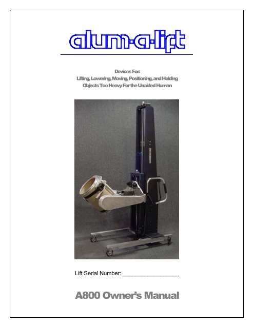
A800 Owner’s Manual
A800 GORILLA LIFT<br />
<strong>Lift</strong> <strong>And</strong> End Effector Guide<br />
NOTE: END-EFFECTORS TO BE USED IN ACCORDANCE WITH<br />
ALUM-A-LIFT APPROVED PROCEDURES<br />
<strong>Alum</strong>-A-<strong>Lift</strong>, Inc.<br />
7909 Bankhead Hwy.<br />
Winston, GA 30187<br />
www.alum-a-lift.com<br />
stanb@alum-a-lift.com<br />
Phone 770 489 0328 - Fax 770 489 7247<br />
DECEMBER 2004, REV A
A800 GORILLA LIFT<br />
Table of Contents<br />
SECTION 1<br />
Setting Up Your <strong>Alum</strong>-A-<strong>Lift</strong><br />
Unpacking the <strong>Lift</strong><br />
Providing Power to the <strong>Lift</strong><br />
Testing the <strong>Lift</strong><br />
SECTION 2<br />
General <strong>Lift</strong> Information<br />
Introduction<br />
Intended Use of the <strong>Lift</strong><br />
Electrical System<br />
Static System<br />
Dynamic System<br />
Ball Screw Advantages<br />
Nameplate<br />
SECTION 3<br />
Operation/Control System<br />
Pendant Box<br />
On/Off/Charge Switch<br />
Circuit Breakers<br />
Charger Status<br />
Fixed Limits<br />
Operating Procedures<br />
<strong><strong>Lift</strong>ing</strong> Load<br />
SECTION 4<br />
End-Effector<br />
SECTION 5<br />
Electrical System<br />
Electrical Safety Concerns<br />
Lockout Instructions<br />
AC Power<br />
DC Power<br />
Battery Basics<br />
Charging the Battery<br />
Battery Specs<br />
SECTION 6<br />
FAQ<br />
APPENDIX 1<br />
Preventative Maintenance<br />
APPENDIX 2<br />
<strong>Lift</strong> Drawings / Photos<br />
APPENDIX 3<br />
Test Certification<br />
Build Standards<br />
Load Test and Tilt Test<br />
APPENDIX 4<br />
Recommended Spares<br />
APPENDIX 5<br />
Electrical Supplement<br />
Schematic
SETTING UP YOUR ALUM-A-LIFT<br />
Setting Up Your <strong>Alum</strong>-A-<strong>Lift</strong><br />
NOTE: Read this section in its entirety before using your <strong>Alum</strong>-A-<strong>Lift</strong>.<br />
Unpacking the <strong>Lift</strong><br />
The <strong>Alum</strong>-A-<strong>Lift</strong> is shipped to you on a wooden pallet. Larger lifts or those going<br />
overseas will be shipped inside a crate. Before unpacking the lift, check to see if there<br />
is any damage to the unit. If there is any damage, please contact the freight carrier,<br />
your traffic person, and our office at once. If it has been ascertained that the lift has not<br />
been damaged, carefully remove the wrapping and check the condition of the unit. <strong>Lift</strong>s<br />
are shipped completely assembled except for the installation of the battery which is<br />
shipped in a box fastened to the pallet. Some exceptions may apply in cases where the<br />
end-effector is removed due to shipping restrictions. In general, the lift will be secured<br />
with banding or boarding which can be removed with the appropriate tooling. Taped to<br />
the <strong>Alum</strong>-A-<strong>Lift</strong> is a manila envelope containing: an owner’s manual, a tool set, “Good<br />
Stuff” ballscrew lubricant, and the final check list. The lift weight will vary according to<br />
the application; therefore care should be exercised in removing the lift from the pallet. It<br />
will usually require two people to do this safely.<br />
Palletized <strong>Lift</strong> Crated <strong>Lift</strong><br />
Section<br />
1
SETTING UP YOUR ALUM-A-LIFT<br />
Providing Power to the <strong>Lift</strong><br />
The lift features a 24VDC battery operated system. This is accomplished by connecting two<br />
12V, 31.5Ah gel cell batteries in series. These come packed in a seperate box. Remove<br />
the batteries from the box and position them on the floor as close to the rear of the lift as<br />
possible. Remove the back cover from the rear of the lift using the captive thumbscrews.<br />
Inside the battery compartment you will find four leads with ring connectors. Each lead is<br />
labeled to aid connection and should be long enough to reach the batteries. Designate one<br />
battery as “A” and the other battery as “B”. Connect each lead to the appropriate battery<br />
and secure using the hardware accompanying the batteries. A battery strap is included in<br />
every lift which can be used to secure the batteries once they are in place. Loosen the strap<br />
so that the battery tray is clear. Each battery weighs about 24 pounds. Note, use SEMI<br />
Type 4 protection when installing the batteries. Carefully lift the batteries onto the battery<br />
tray and secure using the battery strap. Replace the back cover. See the Electrical System<br />
section for more information.<br />
Battery Compartment<br />
(Battery Strap Not Shown)
SETTING UP YOUR ALUM-A-LIFT<br />
Testing the <strong>Lift</strong><br />
Move the ON/OFF/CHARGE switch to the ON position. The voltmeter should now register<br />
24 volts or more and a green LED by the switch should light up. The controls on the<br />
detachable black pendant box should now be active. Press the UP/DOWN controls on the<br />
lift pendant box and the carriage should raise and lower. Run the carriage up and down<br />
throughout the preset range. The motor and brake will make a clicking sound when the<br />
UP/DOWN button is initially depressed; this sound is normal. See the Operational/Controls<br />
Section for more detail regarding operation.<br />
If your lift is equipped with a powered end-effector a second pendant box will be included<br />
with the lift. Test each powered function to verify that the lift is working properly.
A800 GORILLA LIFT<br />
General <strong>Lift</strong> Information<br />
Section<br />
2<br />
Introduction<br />
The lifting device described in this manual is designed to assist personnel in safely removing<br />
and installing equipment while complying with SEMI S2 safety guidelines. This manual<br />
describes the operation, maintenance and use of the lift.<br />
Intended Use of the <strong>Lift</strong><br />
The lift is designed around a specific application. It is intended to raise and lower loads and<br />
to act as a means of transportation where necessary. The lift is designed to work in<br />
conjunction with unique end-effectors intended for the individual components present in<br />
each system.<br />
The <strong>Alum</strong>-A-<strong>Lift</strong> design features three integrated systems: electrical, static, and dynamic.<br />
Electrical System<br />
The electrical system provides power and control to the drive system and end effector. The<br />
system is comprised of:<br />
• Batteries • Circuit Breakers<br />
• Limit Switches • Relays<br />
• Voltmeter • Indicator Lights<br />
• Rocker and Push Button Switches • Low Voltage Indicator<br />
• Speed Controller (where applicable) • EMI Filter (where applicable)<br />
• EMO Switches (where applicable) • Battery Charger<br />
The system operates on 24 volt DC power provided by a pair of 12 volt batteries<br />
connected in series. The lift contains a built in AC powered battery charger that can be<br />
plugged into an AC outlet through the use of the integrated AC power cord. A voltmeter<br />
located on the top cover helps to monitor the voltage of the batteries. As an additional<br />
feature, an audible alert will sound when the battery needs recharging. Ignoring this<br />
alert may result in discharging the batteries. The system should not be operated while<br />
the batteries are charging.
GENERAL LIFT INFORMATION<br />
Static System<br />
The static (framework) provides structure to which the electrical and drive systems are<br />
mounted. This system is comprised of:<br />
• Welded Frame • Leg Assembly<br />
• Base Assembly<br />
• Top Channel Assembly<br />
• Ergonomic Handles<br />
• Struts<br />
The lift is comprised of numerous subsystems. The most basic framework involves the<br />
mounting of a frame assembly to a base assembly. Mounted to the base assembly are<br />
two leg assemblies. These subassemblies make up a very stable and mechanically<br />
strong system.<br />
Dynamic System<br />
The dynamic system (drive) provides motion and power in the form of upward and<br />
downward movements of the carriage. The carriage is designed to accommodate a variety<br />
of end-effectors. The dynamic system includes:<br />
• Gear Motor • Brake<br />
• Alignment Couple • Ball Screw<br />
• Ball Nut Assembly<br />
• Pillow Block Bearings<br />
• Carriage Assembly<br />
The lift’s carriage is driven up and down by a DC gear motor driven ball screw that runs<br />
vertically along the inside of the structure.<br />
Ball Screw Design Advantages 1<br />
“A ball bearing screw is well described by its name; it’s a screw that runs on ball bearings.<br />
The balls provide the only physical contact between screw and nut, replacing the sliding<br />
friction of a conventional screw with a free and smooth rolling motion. In a ball bearing<br />
screw the return tubes carry the ball bearings from the end of their travel, over the screw and<br />
back to the start of the circuit to form a continuously recirculating path. A ball bearing screw<br />
is extremely energy efficient, about 90% – three times more efficient than conventional<br />
screws. The primary function of a ball bearing screw is to convert rotary motion to linear<br />
motion – or torque to thrust.” In the case of the lift, this linear motion is accomplished by<br />
rotating the screw and having the nut travel up or down. A load locking spring is featured on<br />
the <strong>Alum</strong>-A-LIft. This spring is a coil turned into the inactive portion to the nut that conforms<br />
to the ball tract. During normal operation, the spring is inactive and not in contact with the<br />
screw. In the event the ball bearings are lost from the nut, the load locking spring will not<br />
allow the load carrying nut to free-fall down the screw.<br />
1. (http://www.uslinear.com/config/BSHelp/Balscrew/Design_Advantages_of_Ball_Bearing_Screws.htm)
GENERAL LIFT INFORMATION<br />
Ball Bearing Screw<br />
(http://www.uslinear.com/config/BSHelp/Balscrew/Design_Advantages_of_Ball_Bearing_Screws.htm)<br />
Nameplate<br />
Located on the operator side of each lift, a nameplate or placard gives general information<br />
regarding the specifications for that specific lift. Notable items include serial number, vendor<br />
contact information, and load limit. A sample nameplate follows.<br />
<strong>Lift</strong> Nameplate
A800 GORILLA LIFT<br />
Operation/Control System<br />
Pendant Box<br />
The <strong>Alum</strong>-A-<strong>Lift</strong>’s vertical travel is controlled via a detachable pendant box. The pendant<br />
box allows for vertical adjustment of the lift’s carriage. Up and Down push buttons are<br />
located on the front edge of the box. Only one button will function at a time. If equipped, a<br />
speed control knob located on the side of the pendant box allows for fine vertical adjustment<br />
of the lifting speed. The pendant box is attached to the lift by a flexible curly cord. This cord<br />
allows the user freedom of movement while operating the lift.<br />
ON/OFF/CHARGE Button<br />
The top cover contains an ON/OFF/CHARGE button. This button is a three-position toggle<br />
switch.<br />
• The ON position gives power to the lift. The voltmeter shows the output voltage<br />
applied to the circuit. A green LED will light up to indicate the power is on.<br />
• The OFF position turns the lift off.<br />
Section<br />
3<br />
• The CHARGE position switches input voltage via the charging cord to the built in<br />
charger. Do not run the lift while in charge mode.<br />
Circuit Breakers<br />
To protect the electrical system, circuit breakers located on the top cover serve as overload<br />
protection. The lift has four main circuits: a control circuit, an ac in circuit, a dc out circuit,<br />
and a lift main circuit. A fifth circuit will be present if the end-effector is powered. If the<br />
labeled amperage is exceeded, the circuit breaker will pop out and can be reset by pressing<br />
it back down. In the event a circuit breaker is tripped, the cause should be examined<br />
immediately.<br />
Charger Status<br />
A built in charger is included in every lift. The charger is CE approved and switchable<br />
between 110/220V as needed. Either charger is located in the battery compartment. A set<br />
of LEDs located on the top cover alert the operator as to the status of the battery. To charge<br />
the batteries, plug the charger cord (located on the lift’s right side plate) into a standard
OPERATIONAL/CONTROLS SYSTEM<br />
outlet and turn the ON/OFF/CHARGE switch to the CHARGE position. The charger will<br />
not overcharge the batteries.<br />
Fixed Limits<br />
The <strong>Alum</strong>-A-<strong>Lift</strong> is equipped with end-of-travel limit switches. These limit switches stop the<br />
movement of the carriage when depressed. The switches are fixed and initially set at the<br />
factory. Optional redundant limits serve as safety back ups in the event of over travel. This<br />
option is standard for CE lifts and optional for domestic use.<br />
Operating Procedures<br />
The basic operation of the lift is to move loads up and down. The following instructions<br />
summarize how to perform this operation. It is recommended that all lifting operations be<br />
conducted with fully charged batteries and that the battery charger is plugged in when the lift<br />
is not in use. See the Electrical System section for details on charging the batteries.<br />
<strong><strong>Lift</strong>ing</strong> Load<br />
• Switch the three-position ON/OFF/CHARGE switch to the ON position.<br />
• If necessary, attach the appropriate component specific end-effector.<br />
• Move the lift into position.<br />
• Using the up or down buttons on the detachable pendant box, move the carriage up<br />
or down to the desired height.<br />
• Secure the component and lower load to a safe height before moving the lift.
A800 GORILLA LIFT<br />
End Effector<br />
Features<br />
The <strong>Alum</strong>-A-<strong>Lift</strong> is capable of being configured for multiple applications. A custom end<br />
effector is supplied based on the needs of the application. This end-effector has been<br />
designed around specific reach, weight and structural integrity requirements. The posted<br />
load limit of the lift is based on lift stability and end-effector requirements and should not be<br />
exceeded. This could result in lift instability and/or damage to equipment and personnel.<br />
End-effector drawings can be seen on the following page(s).<br />
Section<br />
4<br />
Installing the End Effector<br />
Most of the time the end-effector will come already mounted to the lift. The attachment<br />
method may vary depending on design. In general, eight 3/8-16 flat head socket cap<br />
screws are used to mount the end-effector to the lift’s carriage. Before changing out an endeffector,<br />
first make sure it is <strong>Alum</strong>-A-<strong>Lift</strong> approved and correct for the intended application.<br />
Load Test and Tilt Test<br />
Each end effector is tested and certified to ensure lift stability and structural integrity of the<br />
end effector in accordance with Machinery Directive 98/37/EC. See Appendix 3 for Test<br />
Documentation.
A800 GORILLA LIFT<br />
Electrical System<br />
Electrical Safety Concerns<br />
SEMI S2 safety guidelines define electrical tasks as Type 1-5 based upon the level of<br />
electrical exposure involved.<br />
Type 1 – Equipment is fully de-energized (electrically “cold”)<br />
Type 2 – Equipment is energized. Live circuits are covered or insulated. Work is<br />
performed at a remove location to preclude accidental shock.<br />
Type 3 – Equipment is energized. Live circuits are exposed and accidental<br />
contact is possible. Potential exposures are less than 30Vrms, 42.2 Vpeak, 240<br />
volt-amps, and 20 Joules.<br />
Type 4 – Equipment is energized. Live circuits are exposed and accidental<br />
contact is possible. Voltage potentials are greater than 30Vrms, 42.2 Vpeak, 240<br />
volt-amps, 20 Joules, or radio frequency (rf) is present.<br />
Type 5 – Equipment is energized and measurements and adjustments require<br />
physical entry into the equipment, or equipment configuration will not allow the<br />
use of clamp-on probes.<br />
All electrical tasks described in this manual are Type 4 or less. The Type 4 assignment<br />
is required because of the presence of power levels greater than 240 volt-amps<br />
associated with the batteries. The batteries cannot be turned off and personnel will be<br />
exposed to them when they lockout DC power and/or change the batteries. The<br />
presence of the energy from the batteries could result in an accidental electrical short<br />
circuit resulting in hazardous arcs or flashes. Arcs and flashes may create high<br />
intensity flashes of bright light and discharge sparks or molten material that could injure<br />
personnel and/or damage equipment.<br />
Lockout Instructions<br />
The system has two power circuits, AC and DC. To properly achieve a lockout<br />
condition, both of these circuits must be locked out.<br />
AC Power<br />
• Remove the AC plug from the power outlet.<br />
Section<br />
5
ELECTRICAL SYSTEM<br />
• Replace the plug into the receptacle on the side of the lift.<br />
DC Power<br />
• Put eye protection on (Type 4 task).<br />
• From the back of the lift, remove the back cover to expose the battery.<br />
• Remove the negative wire from the terminals of the battery. Be careful not<br />
to short circuit the positive and negative terminals of the battery, as this<br />
could generated hazardous arcs and flashes.<br />
Battery Basics<br />
A 12-volt battery is not a 12-volt battery. Twelve volts is just a nominal, convenient term<br />
used to distinguish one battery from another. A fully-charged 12-volt battery, allowed to<br />
"rest" for a few hours (or days) with no load being drawn from it (or charge going to it),<br />
will balance out its charge and measure about 12.6 volts between terminals.<br />
When a battery reads only 12 volts under the above conditions, it's almost fully<br />
depleted. Actually, if a battery's resting voltage is only 12.0 to 12.1 it means only 20 to<br />
25% of its useful energy remains. It's either dead or it has been deep cycled, and a<br />
battery can only be deep-cycled a limited number of times before it is indeed dead.<br />
Batteries should be charged if the open circuit voltage drops below 12.4 volts.<br />
Twelve volt batteries supply useful energy only through a limited range -- from over 14<br />
volts (when fully charged) down to 10.5 volts in use/under load.<br />
% Charge Lead Acid Gel Cell<br />
100 12.7-12.6 12.95-12.85<br />
75 12.4 12.65<br />
50 12.2 12.35<br />
25 12.00 12.00<br />
0 11.8 11.8<br />
Charging the Battery<br />
• Switch the three-position ON/OFF/CHARGE switch to the OFF position.<br />
• Insert the AC plug on the lift into a compatible AC outlet.<br />
• Switch the three-position ON/OFF/CHARGE switch to the CHARGE position. The<br />
Charging LED will turn on and the battery will begin to charge.<br />
• The charge is complete when the Charge Complete LED turns on.<br />
• In the event that the batteries do not charge following an extended charging cycle,<br />
the batteries will likely need to be replaced.
ELECTRICAL SYSTEM<br />
Battery Specs<br />
The batteries accompanying the lift are valve-regulated, gelledelectrolyte<br />
batteries designed to offer reliable, maintenance-free<br />
power, for renewable energy applications where frequent deep<br />
cycles are required and minimum maintenance is desirable.<br />
• 12 volts nominal, 31.5 Ah<br />
• Weighs 24 pounds<br />
• Element, post = Threaded stud of “flag” terminal, forged bushing<br />
• Charge voltage = Cycle 2.30 to 2.35; Float 2.25 to 2.30<br />
• Gelled-Electrolyte<br />
• Rated non-spillable by ICAO, IATA, and DOT
A800 GORILLA LIFT<br />
FAQ<br />
Section<br />
6<br />
I Ordered an A800 But The Load Limit Sticker Says 350 Pounds. Did I Get the Wrong<br />
<strong>Lift</strong>?<br />
It is common for the lift to be rated at a load less than the lift model. Each lift is rated based<br />
on the load being 18” off the front of the carriage. Exceeding this distance usually requires a<br />
higher rated lift. The weight of the end-effector and stability of the lift also have to be<br />
considered.<br />
I Turn the <strong>Lift</strong> On, But the Light Doesn’t Come On. What’s Wrong?<br />
The LED may be blown or simply disconnected. Check to make sure the lift is responsive to<br />
the pendant box controls. If so, the LED is the problem and will need to be replaced.<br />
I Turn the <strong>Lift</strong> On, I press the Up / Down Buttons and Nothing Happens. What’s<br />
Wrong?<br />
As simple as this sounds, first check to make sure the On/Off/Charge switch is actually in<br />
the on position. A green LED should light up. If not, check to make sure the leads are<br />
correctly connected to the battery. Push the up and down buttons, check to see if the relays<br />
are clicking. You should be able to audibly tell.<br />
The <strong>Lift</strong> Vibrates and / or Makes Noises When Going Up / Down. What’s Wrong?<br />
This is likely the result of misalignment between the lift motor and the ballscrew. Check the<br />
motor couple located at the front of the lift to see if the couple is misaligned.<br />
The <strong>Lift</strong> is Making a High Pitched Noise. Is There Something Wrong?<br />
The noise is likely coming from the Low Voltage Indicator (LVI). This audible alarm is to<br />
alert the operator that the batteries need to be charged.<br />
Why is the <strong>Lift</strong> Tripping the 3A AC Circuit Breaker?<br />
When batteries are excessively low, the charger will pull more amps in an attempt to charge<br />
the batteries. This will trip the breaker. First try removing the batteries and charging them<br />
with an offline charger. You can also try replacing the circuit breaker, it may be bad. If the<br />
problem persists, the charger may be defective and will need to be replaced.
FAQ<br />
Why is the <strong>Lift</strong> Tripping the 10A Circuit Breaker?<br />
When batteries are excessively low, the charger will pull more amps in an attempt to charge<br />
the batteries. This will trip the breaker. First try removing the batteries and charging them<br />
with an offline charger. You can also try replacing the circuit breaker, it may be bad. If the<br />
problem persists, the charger may be defective and will need to be replaced.<br />
Why is the <strong>Lift</strong> Tripping the 25A Circuit Breaker?<br />
In general, the 25A breaker will trip if the motor begins to draw an excessive amount of<br />
amperage. This can be for several reasons. The most common cause is that the motor<br />
brake is not releasing, thus the motor is fighting the brake. Reset the breaker and remove<br />
the back cover so that you can see the brake, which is mounted to the rear of the motor.<br />
You should be able to see the brake move slightly as you press the up or down buttons. If<br />
not, check your brake connections. If the motor is shorted or you are lifting too heavy a load<br />
the breaker will trip as well. Also check to see if the lift’s carriage seems to be binding or<br />
hitting an obstacle causing extra strain on the motor.<br />
How Long Does It Take to Recharge My Battery?<br />
A specific time is difficult to determine because of many variables:<br />
• Temperature • Degree of discharge<br />
• Charger • Age and condition of battery<br />
It will take about 60% of the charging time to bring a battery from 0% charged (10.5V) to<br />
90% charged. It will take the remaining 40% of the total charging time to add the last 10% of<br />
charge to the battery. In general we recommend that a good overnight charge should be<br />
sufficient.<br />
Will The Charger Overcharge My Battery?<br />
No. We recommend that, when possible, you leave the lift’s charger cord plugged into an<br />
outlet and the switch in the charge position until you next need the lift for use. Once the<br />
charging cycle is complete the charger switches to a constant voltage float/standby mode<br />
(trickle charge), nominally at 2.3 Volts per cell. At this voltage, the battery will not out gas so<br />
any electrolyte loss is minimal. The charge current drops exponentially to a very low level,<br />
sufficient to maintain a fully charged battery. This will actually tend to equalize charge<br />
imbalance between the battery cells over time, which can extend battery life. By leaving the<br />
charger switched on, you will actually prevent any risk of battery damage from sulphation<br />
which results from allowing a battery to remain in a discharged state.<br />
My Charger Isn’t Charging the Battery. Do I Need A New Charger?<br />
Probably not. The chargers feature short circuit and reverse polarity shutdown, so they<br />
don’t produce any output voltage unless they are actually connected to a battery. This is a<br />
safety measure to keep an operator from being shocked if they are holding the leads. If the<br />
battery is excessively discharged then the battery may not start because it can’t detect that<br />
the battery is there. Try putting the battery on an offline charger until it has been charged to<br />
around 11 volts. At this time, it can be placed back in the lift and the onboard charger can<br />
take over.
FAQ<br />
Why Won’t My Battery Hold A Charge?<br />
If the battery won’t hold a charge it is likely due to a damaged battery. This usually is<br />
the result of a damaged cell resulting from the discharge of the battery. If a battery is<br />
well maintained, it will generally last 2-3 years before replacement is needed.
MAINTENANCE<br />
Preventative Maintenance<br />
Ball Screw<br />
Casters<br />
Limit Switches<br />
Battery<br />
Set Screws<br />
Schedule Comments<br />
Lubricate the ball<br />
screw every 2<br />
months or 500<br />
hours of operation.<br />
Check the caster<br />
fastener for tightness<br />
every 2 months.<br />
Check limit switches<br />
every month.<br />
Charge often, at least<br />
once a week.<br />
Check set screws in<br />
bearings, couple, and<br />
motor brake every 6<br />
months.<br />
<strong>Lift</strong> Cleaning Frequently<br />
Fasteners<br />
Every 12 months<br />
Appendix<br />
1<br />
Use only Lithium or Teflon grease to lubricate the<br />
ball screw and linear guides. NO OIL. A supply of<br />
“Good Stuff” lubricant is supplied with the lift and<br />
free replacement bottles are available by<br />
contacting <strong>Alum</strong>-A-<strong>Lift</strong>. Manually apply grease up<br />
and down the screw and run the lift up and down to<br />
help spread the lubricant over the length of the<br />
screw.<br />
Verify that caster is not loose. Refer to tightening<br />
specifications for torque settings.<br />
While jogging the lift up or down, check to see that<br />
the limit switches stop travel or perform the<br />
intended function. Be careful not to “crash” the<br />
carriage at the extremes of travel. See the<br />
Operational/Controls System Section.<br />
The charger will not over charge the battery. The<br />
battery should always be fully charged when the lift<br />
is not in use.<br />
Use appropriate tightening torque (see appendix)<br />
and removable grade thread locking compound.<br />
Dirty or dusty environments may require a more<br />
frequent cleaning schedule.<br />
Inspect for damaged or loose fasteners. Tighten<br />
fasteners according to recommended torque<br />
settings.
A800 GORILLA LIFT<br />
RECOMMENDED TORQUE SETTINGS<br />
Alloy Steel Fasteners [in-lb]<br />
Size Set Screw SHCS BHSCS FHSCS<br />
#6-32 10 34 15 17<br />
#8-32 20 59 30 31<br />
#10-32 36 77 40 45<br />
1/4-20 87 200 100 100<br />
5/16-18 165 425 200<br />
3/8-16 290 750 350<br />
1/2-13 620 1850 850 83<br />
Stainless Steel Fasteners [in-lb]<br />
Size Set Screw SHCS BHSCS FHSCS<br />
#6-32 7 15 11 11<br />
#8-32 16 28 20 20<br />
#10-32 26 40 30 30<br />
1/4-20 70 95 71 71<br />
5/16-18 130 170 123 123<br />
3/8-16 230 300 218 218<br />
1/2-13 500 750 532 532<br />
SHCS - Socket Head Cap Screw<br />
BHSCS - Ball Head Socket Cap Screw<br />
FHSCS - Flat Head Socket Cap Screw<br />
ref: Unbrako Engineering Guide, Form 5519 REV. A 20M 697<br />
SPS
A800 GORILLA LIFT<br />
<strong>Lift</strong> Drawings / Photos<br />
Appendix<br />
2
LIFT DRAWINGS / PHOTOS<br />
A800<br />
Ergonomic Handles<br />
Heavy Duty Casters<br />
Reinforced Leg<br />
Top Channel Assembly<br />
Carriage Assembly<br />
Boxbeam Baseplate
LIFT DRAWINGS / PHOTOS<br />
A800CS<br />
Continuous Sideplate
LIFT DRAWINGS / PHOTOS
A800 GORILLA LIFT<br />
Test Certification<br />
Appendix<br />
3<br />
Build Standards<br />
<strong>Alum</strong>-A-<strong>Lift</strong>s are assessed against all available build standards in order to ensure a fully<br />
functional, yet safe and ergonomic solution to general lifting requirements. If it is<br />
desired that the lift be built to a certain specification this should be discussed during the<br />
quotation stage. Most assessments are done on a self certifying basis. Formal third<br />
part testing for each lift is available upon request.<br />
Load Test and Tilt Test<br />
Each lift is certified to ensure the stability and structural integrity of the lift in accordance with<br />
Machinery Directive 98/37/EC. This was done two ways. First, theoretical tilt diagrams<br />
were generated based on data collected from wire frame and solid models. Second, the<br />
theoretical data was verified through actual tilt tests when necessary.
TEST CERTIFICATION<br />
DECLARATION OF CONFORMITY<br />
Manufacturer: <strong>Alum</strong>-A-<strong>Lift</strong>, Inc.<br />
7909 Bankhead Hwy<br />
Winston, GA 30187, U.S.A.<br />
Product: Ergonomic <strong><strong>Lift</strong>ing</strong> Equipment<br />
Serial Number: ________________________<br />
Complies with Directives: 98/37/EC Machinery Directive (previously<br />
9/392/EEC)<br />
89/336/EEC Electromagnetic Compatibility<br />
Directive, as amended<br />
73/23/EEC Low Voltage Directive<br />
Harmonized Standards Reference: EN 292, Part 2, Appendix A, Safety of machinery -<br />
Basic concepts, general principles for design, Part<br />
2. Technical principles and specifications<br />
EN 61010-1, Part 1, Safety requirements for<br />
electrical equipment for measurement, control, and<br />
laboratory use<br />
EN 61000-6-2, Generic standards-Immunity for<br />
Industrial environment<br />
EN 60204-1, Part 1, Safety of machinery-Electrical<br />
equipment of machines<br />
EN 55014-1:1997 - Electromagnetic compatibility.<br />
Conducted Disturbance Emissions-Voltage<br />
Terminal Disturbance Power Emissions<br />
Underwriters Laboratories, Inc.<br />
File : MC1385<br />
Contact Person: Eric Bressner<br />
Vice President, <strong>Alum</strong>-A-<strong>Lift</strong>, Inc.<br />
This product, which bears the CE Marking, has been assessed against the Machinery Directive<br />
(98/37/EC) and complies with the Essential Health and Safety Requirements therein. This product<br />
also complies with the Principal Elements of Safety Objectives of the Low Voltage Directive<br />
(73/23/EEC).<br />
As the manufacturer of the above apparatus, we declare that the product conforms with the protection<br />
requirements of Council Directive 89/336/EEC on the approximation of the laws relating to<br />
electromagnetic compatibility.<br />
This Declaration of Conformity is based on the results of analysis, testing and evaluation performed by<br />
<strong>Alum</strong>-A-<strong>Lift</strong>.<br />
_______________________________________<br />
Design Engineer<br />
This Declaration of Conformity and Marking on the equipment signifies compliance to all applicable CE Marking Directives, as noted above, at the time of<br />
initial shipment by <strong>Alum</strong>-A-<strong>Lift</strong>, Inc. For products initially installed outside of the European Union (EU), it is the Importer of Record's responsibility to ensure<br />
that the product remains in conformance with all applicable Directives upon first entry into the EU.
A800 GORILLA LIFT<br />
Recommended Spares<br />
Appendix<br />
4<br />
Recommended Spare Parts<br />
With the exception of battery replacement, the system doesn’t have any parts that will<br />
require replacement short of failure. Vended items which will require replacement in the<br />
event of failure are carried in stock by <strong>Alum</strong>-A-<strong>Lift</strong> and are available on a next day basis.<br />
A list of recommended spare parts follows on the next page if internal policies require<br />
that an in house inventory be carried. If repairs are required, contact an <strong>Alum</strong>-A-<strong>Lift</strong><br />
representative.<br />
Battery Replacement<br />
The battery will occasionally need to be replaced. The frequency of replacement will<br />
depend on how often the lift is used, the load being lifted, and how often the battery is<br />
charged. When replacing the battery, keep in mind that it is critical that the battery be<br />
replaced with one that has the same specifications as the one currently installed. See<br />
the Electrical System for more information on the battery. The battery appears on the<br />
recommended spares list for reference. It may be considered unwise to carry a spare<br />
battery as it will discharge over time unless maintained.
RECOMMENDED SPARES<br />
RECOMMENDED SPARES FEB-5-2003<br />
PART NUMBER DESCRIPTION MODEL<br />
A40-636 Battery, Gel Cell, 31.5Ah A800<br />
V-BRK-24VDC Brake, Electric - 24VDC A800<br />
A40-309-002 Charger, 8AMP 24V 110/220V A800<br />
A40-534 Circuit Breaker, 10A ALL<br />
A40-538 Circuit Breaker, 25A ALL<br />
A40-531 Circuit Breaker, 3A ALL<br />
A70-128 Grips, Sponge ALL<br />
A40-101/B Motor, 500rpm, 24V A800<br />
A40-535 Pendant Box Assembly, Up/Down ALL<br />
A40-090 Speed Controller, 12/24VDC A800<br />
A40-519/N Switch, Rocker, 3 Position - ON/OFF/CHARGE ALL<br />
A40-665 Relay, 40amp ALL<br />
CASTER SET-SELECT APPROPRIATE SET ONLY<br />
A70-530/S Caster Set, HW, 3-1/2" - 4 Sw A800<br />
A70-530/T Caster Set, HW, 3-1/2" - 2 Sw, 2 Br A800<br />
A70-540/T Caster Set, HW, 4" - 2 Sw, 2TL A800<br />
A70-550/T Caster Set, HW, 5" - 2 Sw, 2TL A800
A800 GORILLA LIFT<br />
Electrical Supplement<br />
Appendix<br />
5