LLVM-Based C Compiler for the PicoBlaze Processor - Institute of ...
LLVM-Based C Compiler for the PicoBlaze Processor - Institute of ...
LLVM-Based C Compiler for the PicoBlaze Processor - Institute of ...

Create successful ePaper yourself
Turn your PDF publications into a flip-book with our unique Google optimized e-Paper software.
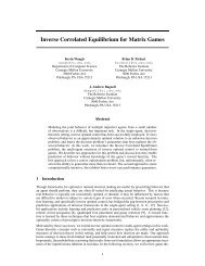
<strong>LLVM</strong>-<strong>Based</strong> C <strong>Compiler</strong><strong>for</strong> <strong>the</strong> <strong>PicoBlaze</strong> <strong>Processor</strong>Technical ReportJaroslav Sýkora<strong>Institute</strong> <strong>of</strong> In<strong>for</strong>mation Theory and Automation <strong>of</strong> <strong>the</strong> ASCRPod Vodarenskou vezi 4, CZ-182 08, Prague 8Abstract. The implementation <strong>of</strong> <strong>the</strong> optimizing C compiler <strong>for</strong> <strong>the</strong>Xilinx <strong>PicoBlaze</strong> architecture is presented. The compiler is implementedin <strong>the</strong> open-source <strong>LLVM</strong> 2.9 framework. The description focuses on <strong>the</strong>issues specific to <strong>the</strong> <strong>PicoBlaze</strong> code generation process.The compiler will be made available free <strong>of</strong> charge <strong>for</strong> evaluation andnon-commercial use at UTIA’s web pages:http://sp.utia.cz/index.php?ids=pblaze-cc.1 IntroductionOne may argue that <strong>the</strong> efficiency and speed <strong>of</strong> a compiler <strong>for</strong> a processor architectureis as critical to <strong>the</strong> success <strong>of</strong> <strong>the</strong> product as <strong>the</strong> processor microarchitectureand its implementation itself. For from <strong>the</strong> point <strong>of</strong> view <strong>of</strong> a naïve hardwaredesigner it is not that difficult to design a high-per<strong>for</strong>mance architecture, yet itmay be impossible to compile programs <strong>for</strong> it. For example <strong>the</strong> FPGA 1 chip canbe viewed as a massively parallel processor, yet we have not seen an efficientcompiler <strong>of</strong> <strong>the</strong> common C language <strong>for</strong> it. On <strong>the</strong> o<strong>the</strong>r hand, when s<strong>of</strong>twareengineers design a processor architecture and a compiler <strong>for</strong> it, <strong>the</strong>y may simplify<strong>the</strong> architecture too much <strong>for</strong> <strong>the</strong> sake <strong>of</strong> an efficient compilation process, and unknowinglysacrifice <strong>the</strong> per<strong>for</strong>mance <strong>of</strong> a future hardware implementation. Thisis one <strong>of</strong> <strong>the</strong> reasons why Google re-defined <strong>the</strong> Java Virtual Machine, originallya stack-based interpreted processor architecture, to use not-so-compiler-friendlyregister architecture to increase speed and lower memory footprint [1].1.1 <strong>PicoBlaze</strong> <strong>Processor</strong> Architecture<strong>PicoBlaze</strong> [6] is a simple 8 bit processor that can be instantiated in Xilinx FPGAchips. Its intended role is to per<strong>for</strong>m simple control functions in places wherea hard-coded state automaton would be too complicated and inflexible, yet afull-fledged RISC processor (such <strong>the</strong> 32 bit MicroBlaze) too costly.The architecture diagram is in Figure 1. The <strong>PicoBlaze</strong> ISA is orthogonal,having 16 general-purpose registers (GPR), each 8 bits wide. The registers are1 FPGA = Field-Programmable Gate Array
Fig. 1: The architecture <strong>of</strong> <strong>the</strong> <strong>PicoBlaze</strong> CPU. Picture is from [6].named %s0 – %s9, and %sA – %sF. All <strong>the</strong> registers are completely symmetric,and none has any special meaning in <strong>the</strong> hardware. The processor ALU has a2 bit flag register with <strong>the</strong> CARRY and ZERO flags.All instructions execute in two clock cycles, without any overlap (<strong>the</strong>re is nopipelining). The instructions are two-address, meaning that in binary operationsone <strong>of</strong> <strong>the</strong> input register is also <strong>the</strong> output register. Program address space anddata address space are separated (Harvard architecture). The ISA is Load/Storebecause ALU operations operate exclusively on <strong>the</strong> GP registers.1.2 Previous <strong>PicoBlaze</strong> <strong>Compiler</strong> AttemptsFor <strong>the</strong> purpose <strong>of</strong> this report two specific previous C compilers <strong>for</strong> <strong>the</strong> <strong>PicoBlaze</strong>architecture will be discussed as <strong>the</strong>y are in use in <strong>the</strong> author’s research department.The first one is <strong>the</strong> famous ‘pccomp’ compiler from Francesco Poderico[4]. The main ‘disadvantage’ <strong>of</strong> <strong>the</strong> compiler is that it was found practically unusabledue to a high number <strong>of</strong> bugs. Even simple test programs are sometimesmiscompiled [7].The second work is <strong>the</strong> bachelor <strong>the</strong>sis by B. Nováček [7]. He implemented astack-based syntax-driven C compiler from scratch. Although <strong>the</strong>re were somebugs, <strong>the</strong> compiler is quite operational. The disadvantage <strong>of</strong> <strong>the</strong> compiler isits relatively high instruction overhead due to <strong>the</strong> primitive stack-based codegenerator.2 The <strong>LLVM</strong> <strong>Compiler</strong> FrameworkThe <strong>LLVM</strong> 2 [2] compiler framework is an open source collection <strong>of</strong> libraries andtools written in C++ <strong>for</strong> building and experimenting with compilers. O<strong>the</strong>r sim-2 <strong>LLVM</strong> = Low-Level Virtual Machine, though <strong>the</strong> acronym no longer holds any propermeaning.2
ilar frameworks include <strong>for</strong> example <strong>the</strong> Stan<strong>for</strong>d SUIF system, <strong>the</strong> commercialCoSy compiler technology, and – <strong>of</strong> course – <strong>the</strong> GNU GCC toolchain.Figure 2 shows <strong>the</strong> flow <strong>of</strong> data in <strong>the</strong> compiler system. The frameworkis built around a well-defined intermediate representation (<strong>LLVM</strong> IR [3]). Thefrontend tool (‘Clang’ in <strong>the</strong> case <strong>of</strong> C/C++ languages) parses <strong>the</strong> source codelanguage (C/C++) into an internal AST (Abstract Syntax Tree) representation,which may be language-specific, and <strong>the</strong>n lowers it into <strong>the</strong> language- and targetindependent<strong>LLVM</strong> IR. There are three possible physical <strong>for</strong>mats <strong>of</strong> <strong>the</strong> IR:1. an in-memory representation using C++ objects;2. a human-readable text file (with <strong>the</strong> .ll file extension);3. and a binary ‘bitcode’ file (.bc) that should load faster than <strong>the</strong> textual .llfile.The three <strong>for</strong>mats are logically equivalent, and <strong>the</strong>y can be trans<strong>for</strong>med fromone to ano<strong>the</strong>r without in<strong>for</strong>mation loss. Target-independent optimizations areper<strong>for</strong>med in <strong>the</strong> <strong>LLVM</strong> IR, <strong>of</strong>ten by invoking <strong>the</strong> OPT tool (though usually <strong>the</strong>optimizations and code generation are per<strong>for</strong>med within one program to speedup <strong>the</strong> compilation process).Target code generation is per<strong>for</strong>med in <strong>the</strong> LLC tool. The target ISA 3 descriptioncomprises custom C++ code and ‘tablegen’ declarations (describedbelow). Some target description is also required in <strong>the</strong> CLANG frontend; however,this is quite insignificant (on <strong>the</strong> order <strong>of</strong> 50 source code lines in C++),and generally <strong>the</strong> frontend only needs to know <strong>the</strong> bit sizes <strong>of</strong> various data types<strong>of</strong> <strong>the</strong> target architecture (i.e. how <strong>the</strong> various int types are wide in <strong>the</strong> ISA).3 The Target-Independent <strong>LLVM</strong> IRThe <strong>LLVM</strong> IR [3] is target- and language-independent representation because its<strong>for</strong>mal structure and <strong>the</strong> range <strong>of</strong> opcodes (nodes) is pre-defined in <strong>the</strong> framework.However, a C/C++ program compiled from its source code into <strong>the</strong> IR isnot portable to a different architecture, because <strong>the</strong> CLANG language frontendhas already made some decisions based on <strong>the</strong> intended target architecture (<strong>for</strong>example <strong>the</strong> layout <strong>of</strong> data in memory, <strong>the</strong> bit widths <strong>of</strong> data).The textual <strong>for</strong>mat <strong>of</strong> <strong>the</strong> IR looks like an assembler <strong>for</strong> a virtual RISC-likeprocessor. The elementary instructions <strong>of</strong> <strong>the</strong> virtual processor are three-address(two input registers, one output register, but <strong>the</strong>re are some exceptions). Theyoperate on an infinite set <strong>of</strong> typed virtual registers; <strong>the</strong> registers are created asneeded, <strong>the</strong>y can be given a name, and each register is assigned exactly once sothat <strong>the</strong> IR is implicitly in <strong>the</strong> SSA <strong>for</strong>m.Examples: Multiply a 32 b value (IR type ‘i32’) in <strong>the</strong> virtual register %X by8, <strong>the</strong> result goes into a new virtual register which is named ‘%result’:%result = mul i32 %X, 83 ISA = Instruction Set Architecture3
Fig. 2: General compiling flow in <strong>the</strong> <strong>LLVM</strong> framework.After strength reduction (multiplication replaced by left shift by 3; note <strong>the</strong>‘i8’ (integer 8 bit) type <strong>of</strong> <strong>the</strong> constant):%result = shl i32 %X, i8 3And <strong>the</strong> hard way:%0 = add i32 %X, %X ; yields {i32}:%0%1 = add i32 %0, %0 ; yields {i32}:%1%result = add i32 %1, %1The last example illustrates <strong>the</strong> use <strong>of</strong> comments in <strong>the</strong> code–<strong>the</strong>y start with<strong>the</strong> ’;’ character and run till <strong>the</strong> end <strong>of</strong> <strong>the</strong> line. When a new temporary virtualregister is needed, it is simply named by assigning a number in sequence (%0,%1, ...). Virtual register names begin with <strong>the</strong> % character. Global symbol names(functions, global variables) begin with <strong>the</strong> @ character, e.g. ‘@foo’.4
The IR typing system is simple, yet effective. Elementary integer types <strong>of</strong>any bit widths can be expressed using <strong>the</strong> ‘iN’ syntax, <strong>for</strong> example i1, i8, i32,i80, and so on. (The language frontend lowers <strong>the</strong> plat<strong>for</strong>m-independent C typeint into <strong>the</strong> target-dependent i32 (most 32 bit processors), or i16 type (e.g. <strong>the</strong><strong>PicoBlaze</strong> ISA).) Aggregate types are arrays (e.g. ‘[40 x i32]’ = array <strong>of</strong> 40 32-bitinteger values), vectors (e.g. ‘’ = vector <strong>of</strong> 4 32-bit integer values), andstructures (e.g. ‘{ i32, i32, i32 }’ = a triple <strong>of</strong> three i32 values). There are als<strong>of</strong>unction types, pointers, and opaque (unresolved) types.Two aggregate types are deemed identical when <strong>the</strong>ir structure is <strong>the</strong> same.The names <strong>of</strong> such identical types are just aliases to <strong>the</strong> same underlying type.The implementation ensures that internally <strong>the</strong>re is exactly one unique objectrepresenting <strong>the</strong> type. In practice this means that checking <strong>for</strong> type equivalencein <strong>the</strong> compiler is as cheap as a pointer comparison.4 The Target-Independent OptimizationsFigure 3 shows a simple source program in C. After partial compilation usingCLANG <strong>the</strong> <strong>LLVM</strong> IR in <strong>the</strong> human-readable <strong>for</strong>mat (.ll file) can be obtained(Figure 4). In <strong>the</strong> later figure <strong>the</strong> compilation was intentionally per<strong>for</strong>med withoutany target-independent optimizations (i.e. at level -O0). The structure <strong>of</strong><strong>the</strong> <strong>for</strong> loop can be clearly seen in <strong>the</strong> unoptimized code. Also note <strong>the</strong> explicituse <strong>of</strong> stack <strong>for</strong> <strong>the</strong> local variable ‘i’.The optimization passes can be per<strong>for</strong>med using <strong>the</strong> OPT program. The result<strong>of</strong> level 3 target-independent optimizations (-O3) is in Figure 5. The number<strong>of</strong> basic blocks was reduced, and <strong>the</strong> local variable ‘i’ was moved from stack tovirtual registers. As <strong>the</strong> <strong>LLVM</strong> IR is kept in <strong>the</strong> static single assignment <strong>for</strong>m(SSA), <strong>the</strong> Φ node at line 10 is used to assign <strong>the</strong> current value <strong>of</strong> <strong>the</strong> inductionvariable ‘i’ to <strong>the</strong> virtual register %0 based on <strong>the</strong> incoming control flow (zero ifcoming from ‘bb.nph’, or %inc if coming from <strong>the</strong> ‘<strong>for</strong>.body’ basic block).Fig. 3: A simple loop in C.1 extern void p r i n t ( unsigned char i ) ;23 int testmain ( )4 {5 unsigned char i = 0 ;6 <strong>for</strong> ( ; i < 2 5 0 ; ++i ) {7 p r i n t ( i ) ;8 }9 return 4 2 ;10 }5
Fig. 4: A simple loop from Figure 3 after compilation to <strong>the</strong> <strong>LLVM</strong> IR, without anyoptimizations (-O0).1 ; ModuleID = ’ e001 . c ’2 target datalayout = ”e−p :8:8:8 − i 8 :8:8 − i 1 6 :8:8 − i 3 2 :8:8 − f 3 2 :32:32 − n8”3 target t r i p l e = ” pblaze−−”45 define i16 @testmain ( ) nounwind {6 entry :7 %i = alloca i8 , align 18 store i8 0 , i8 ∗ %i , align 19 br label %f o r . cond1011 f o r . cond :; preds = %f o r . inc , %e n t r y12 %tmp = load i8 ∗ %i , align 113 %conv = zext i8 %tmp to i1614 %cmp = icmp s l t i16 %conv , 25015 br i1 %cmp , label %f o r . body , label %f o r . end1617 f o r . body :; preds = %f o r . cond18 %tmp2 = load i8 ∗ %i , align 119 c a l l void @print ( i8 zeroext %tmp2 )20 br label %f o r . i n c2122 f o r . i n c :; preds = %f o r . body23 %tmp3 = load i8 ∗ %i , align 124 %i n c = add i8 %tmp3 , 125 store i8 %inc , i8 ∗ %i , align 126 br label %f o r . cond2728 f o r . end :; preds = %f o r . cond29 ret i16 4230 }3132 declare void @print ( i8 zeroext )6
Fig. 5: A simple loop from Figure 3 after compilation to <strong>the</strong> <strong>LLVM</strong> IR, with targetindependentoptimizations per<strong>for</strong>med (-O3).1 ; ModuleID = ’ e001 . O0 . l l ’2 target datalayout = ”e−p :8:8:8 − i 8 :8:8 − i 1 6 :8:8 − i 3 2 :8:8 − f 3 2 :32:32 − n8”3 target t r i p l e = ” pblaze−−”45 define i16 @testmain ( ) nounwind {6 bb . nph :7 br label %f o r . body89 f o r . body :; preds = %f o r . body , %bb . nph10 %0 = phi i8 [ 0 , %bb . nph ] , [ %inc , %f o r . body ]11 t a i l c a l l void @print ( i8 zeroext %0) nounwind12 %i n c = add i8 %0, 113 %e x i t c o n d = icmp eq i8 %inc , −614 br i1 %exitcond , label %f o r . end , label %f o r . body1516 f o r . end :; preds = %f o r . body17 ret i16 4218 }1920 declare void @print ( i8 zeroext )7
5 The Code Generation ProcessFigure 6 shows <strong>the</strong> organization <strong>of</strong> <strong>the</strong> code generation process. The processbegins with <strong>the</strong> target-independent <strong>LLVM</strong> IR that is trans<strong>for</strong>med in severalsteps into <strong>the</strong> final assembly source code in <strong>the</strong> target ISA.Fig. 6: The LLC code generator.The first phase <strong>of</strong> <strong>the</strong> process – <strong>the</strong> instruction selection phase – is <strong>the</strong> mostinvolved in regards to <strong>the</strong> target-dependent in<strong>for</strong>mation and algorithms thatmust be supplied to <strong>the</strong> compiler by a developer; thus this report will focus on<strong>the</strong> phase. The o<strong>the</strong>r phases are much more target-independent, or <strong>the</strong>y requireonly small portions <strong>of</strong> target in<strong>for</strong>mation (e.g. <strong>the</strong> register allocation phase).8
5.1 Building <strong>the</strong> Initial SelectionDAGThe instruction selection phase <strong>of</strong> <strong>the</strong> code generation process is carried outusing a so-called SelectionDAG representation <strong>of</strong> <strong>the</strong> code. SelectionDAG is acontrol-data-flow directed acyclic graph <strong>of</strong> operation nodes. The input <strong>LLVM</strong> IRis converted into <strong>the</strong> representation at <strong>the</strong> beginning. For each basic block <strong>of</strong> <strong>the</strong><strong>LLVM</strong> IR a stand-alone SelectionDAG is created. The nodes <strong>of</strong> <strong>the</strong> graph (operations)initially correspond to <strong>the</strong> instructions in <strong>the</strong> input <strong>LLVM</strong> IR, though <strong>the</strong>mapping is not 1:1. During <strong>the</strong> course <strong>of</strong> <strong>the</strong> code generation process <strong>the</strong> abstracttarget-independent operations in <strong>the</strong> graph are gradually morphed into targetdependentCPU instructions. Ideally, <strong>the</strong> instruction selection process would bea simple pattern matching task, however, this is regrettably not always <strong>the</strong> case.Figure 7 shows <strong>the</strong> initial SelectionDAG <strong>of</strong> <strong>the</strong> <strong>for</strong>.body basic block <strong>of</strong> <strong>the</strong>optimized <strong>LLVM</strong> IR from Figure 5. The SelectionDAG pictures can be automaticallygenerated by <strong>the</strong> LLC tool as a debugging aid <strong>for</strong> compiler developers.The arrows in <strong>the</strong> graph represent data and control dependencies, thus <strong>the</strong>ygo against <strong>the</strong> normal flow <strong>of</strong> data and control. Pure data dependencies areshown using full black lines. As some operations can have side effects that mustbe taken into <strong>the</strong> account during scheduling (function calls, memory loads andstores), <strong>the</strong> particular operation nodes must be connected by dependency chainsto explicitly state <strong>the</strong>ir relative ordering. A special TokenFactor node can beused to split a chain into parallel branches. The chains are shown using bluedashed lines. Some instructions can also have implicit dependencies through <strong>the</strong>machine flags (e.g. compare+branch). These are modeled using <strong>the</strong> special flagdependency (more appropriately called glue in <strong>the</strong> newer version <strong>of</strong> <strong>the</strong> <strong>LLVM</strong>framework), which is shown in full red line in <strong>the</strong> picture.SelectionDAG operation nodes can have multiple outputs (e.g. an ADD instructionmay define a register and a flag). This is in contrast to <strong>the</strong> <strong>LLVM</strong> IRin which each instruction has at most one result. The initial SelectionDAG inFigure 7 uses mostly target-independent operations (add, xor, brcond, setcc),although some nodes are already from <strong>the</strong> target opcode space (PBISD::CALL,but this is not a target instruction yet!). We will use <strong>the</strong> notation where targetindependentcodes are written in lower-case letters (e.g. add), while targetspecificcodes and CPU instruction will be written using (mostly) <strong>the</strong> upper-casecharacters (e.g. ADDNCkk, COMPAREkk, JUMP cond).The example graph in Figure 7 can be logically separated into three partsthat loosely correspond to <strong>the</strong> lines 11, 12, and 13–14 in Figure 5. The subroutinecall at line 11 is represented by callseq start, PBISD::CALL, and callseq endnodes. (Also note <strong>the</strong> CopyToReg node marked 0x2f6c820 which puts <strong>the</strong> variable‘i’ into <strong>the</strong> physical register %s0 as per <strong>the</strong> function calling convention.) Theinteger addition at line 12 is represented by <strong>the</strong> add node marked 0x2f6cd20.Finally, <strong>the</strong> conditional branch at line 13–14 is represented by <strong>the</strong> setcc, seteq,xor, and brcond nodes. The brcond node is a generic branch conditioned ona boolean value (type ‘i1’). This boolean value is generated by <strong>the</strong> setcc nodewhich compares <strong>the</strong> result <strong>of</strong> <strong>the</strong> addition (see operand 0 <strong>of</strong> <strong>the</strong> setcc node)with <strong>the</strong> constant value -6 (operand 1), using <strong>the</strong> equal-to condition (seteq,9
TargetConstantRegister %reg16384 [ORD=1]EntryToken [ORD=1]0x2f6c3200x2f42078i80x2f6c520i8Register %S00x2f6c720i8TargetGlobalAddress 00x2f6c920ch0 1 2PBISD::CALL0x2f6ca20ch flagConstant [ORD=2]0x2f6e5a0i8seteq [ORD=2]0x2f6e6a0ch0 1 2 3callseq_end0x2f6cb20ch flag0 1 2setcc [ORD=2]0x2f6e7a0i1chConstant0x2f6e8a0i10 1TokenFactor0x2f6eba0ch0 1xor0x2f6e9a0i1BasicBlock0x2f6eaa0ch0 10 1 2brcond0x2f6eca00 1callseq_startCopyFromReg [ORD=1]0x2f6c620chGlobalAddress 0GraphRoot0x2f6c420i8dag-combine1 input <strong>for</strong> testmain:<strong>for</strong>.body0x2f6c220ch flagi8 ch0 1 2CopyToReg0x2f6c820ch flagConstant [ORD=1]0x2f6cc20i80 1add [ORD=1]0x2f6cd20i8Register %reg163850x2f6ce20i8ValueType:i80x2f6c120ch0 1 2CopyToReg0x2f6cf2010chFig. 7: Initial SelectionDAG <strong>of</strong> <strong>the</strong> ‘<strong>for</strong>.body’ basic block from Figure 5 (optimizedversion <strong>of</strong> <strong>the</strong> example code).
operand 2). The boolean result is negated using <strong>the</strong> xor node, and <strong>the</strong>n fed into<strong>the</strong> brcond node. An optimization pass will collapse <strong>the</strong> xor node by inverting<strong>the</strong> condition test in <strong>the</strong> setcc node.5.2 SelectionDAG Legalization PassesThe initial SelectionDAG can potentially use data types and operations that arenot directly available in <strong>the</strong> target machine architecture. A typical example is16 bit integer type on an 8 bit ISA architecture. In this case <strong>the</strong> compiler has toexpand <strong>the</strong> 16 bit operation into a sequence <strong>of</strong> 8 bit ones. For example, a 16 bitaddition using <strong>the</strong> add node will be expanded into a subgraph <strong>of</strong> addc and addenodes with a dependency on <strong>the</strong> flags. This compiler pass is called legalization,or lowering.Similarly, <strong>the</strong> compiler can automatically expand some operations that arenot supported in <strong>the</strong> target. Examples include division, shifts, and some kinds<strong>of</strong> branches. For each combination <strong>of</strong> <strong>the</strong> target-independent SelectionDAG operationand data type, it is possible to specify an action that <strong>the</strong> legalizer shouldtake. The actions are:– Legal – The target natively supports this operation.– Promote – This operation should be executed in a larger type.– Expand – Try to expand this to o<strong>the</strong>r operations, o<strong>the</strong>rwise use a libcall.– Custom – Use <strong>the</strong> LowerOperation() hook to implement custom lowering.The custom lowering action usually replaces <strong>the</strong> problematic operation node(and possibly some nodes around it) with a target-specific custom node. (Exampletrans<strong>for</strong>mations implemented <strong>for</strong> <strong>the</strong> <strong>PicoBlaze</strong> target will be given later.)5.3 Instruction Selection Using TableGenOnce a SelectionDAG, which represents one basic block, has been legalized byexpanding/promoting illegal data types and operations, possibly by introducingcustom target-specific operation nodes, <strong>the</strong> instruction selection phase cantake place. Theoretically, <strong>the</strong> instruction selector matches a DAG pattern representinga CPU instruction to a subgraph in <strong>the</strong> SelectionDAG. In <strong>LLVM</strong> <strong>the</strong>primary way to specify instruction patterns <strong>for</strong> matching is by TableGen [5] tool.TableGen allows a compiler developer to describe <strong>the</strong> target CPU architectureusing a declarative syntax that is easier to maintain than a custom C++ code.Ideally, <strong>the</strong> whole target architecture would be described in TableGen, requiringno custom C++ code to be written, but <strong>the</strong> <strong>LLVM</strong> framework is not <strong>the</strong>re yet.The target CPU instruction patterns are described in ‘.td’ files. During compilerbuild <strong>the</strong> TableGen tool translates <strong>the</strong> .td files into C++ code which is<strong>the</strong>n included in <strong>the</strong> build process.Figure 8 shows a simplified example <strong>of</strong> a snippet <strong>of</strong> <strong>the</strong> ‘.td’ file from <strong>the</strong> <strong>PicoBlaze</strong>code generator. In <strong>the</strong> example two instructions are defined: ADDkk andADDsy, representing two <strong>for</strong>mats <strong>of</strong> <strong>the</strong> <strong>PicoBlaze</strong> ADD instruction. The ADDkk11
variant <strong>of</strong> <strong>the</strong> addition has an immediate 8 bit value as <strong>the</strong> second operand, while<strong>the</strong> ADDsy instruction takes <strong>the</strong> second operand from a register. The instructionsare defined as instances <strong>of</strong> InstPB class. The parameters <strong>for</strong> <strong>the</strong> class instantiationare given inside <strong>the</strong> arrow brackets. The o<strong>the</strong>r way <strong>of</strong> defining parametervalues is by <strong>the</strong> let command that allows to override parameters in multiple instancesat once. In <strong>the</strong> example it is used in <strong>the</strong> Defs and Constraints parametersat line 1.Fig. 8: TableGen definitions <strong>of</strong> two related <strong>PicoBlaze</strong> instructions ADDkk and ADDsy.1 l e t Defs = [FLAGS] , C o n s t r a i n t s = ” $ s r c=$dst ”2 in {3 def ADDkk : InstPB;89 def ADDsy : InstPB;14 }The InstPB class defines a new CPU instruction. It has four parameters:– List <strong>of</strong> outputs: (outs IntRegs:$dst) – <strong>the</strong> output is a single register from <strong>the</strong>integer registers class IntRegs, named $dst here <strong>for</strong> <strong>the</strong> substitution purposes.– List <strong>of</strong> inputs: (ins IntRegs:$src, i8imm:$k) – <strong>the</strong> first input is an integerregister $src, <strong>the</strong> second input is an 8 bit immediate constant $k.– Assembly output string: ”ADD $dst, $k” – in <strong>the</strong> code emission phase <strong>the</strong>parameters are substituted and <strong>the</strong> string is printed into <strong>the</strong> ‘.s’ assemblerfile.– DAG pattern <strong>for</strong> matching: [(set IntRegs:$dst, (addc IntRegs:$src, simm8:$k))]– <strong>the</strong> pattern is visualized in Figure 9. The pattern matches <strong>the</strong> targetindependentaddc node (‘addition with carry output, no carry in’) that hasan integer register and a signed 8 bit constant as its arguments.The Defs=[FLAGS] parameter, specified by <strong>the</strong> let command, indicates that<strong>the</strong> instruction sets (‘defines’) <strong>the</strong> FLAGS register as its side-effect. The Constraintsparameter can be used to place additional restrictions on <strong>the</strong> instruction.In this case it <strong>for</strong>ces <strong>the</strong> $src and $dst registers to be physically <strong>the</strong> same because<strong>the</strong> instruction is two-address. As <strong>the</strong> <strong>LLVM</strong> target-independent instructions arethree-address, this is an important point. During <strong>the</strong> instruction selection phase12
Fig. 9: The DAG pattern <strong>of</strong> <strong>the</strong> ADDkk <strong>PicoBlaze</strong> instruction as modelled in <strong>the</strong> .tdfile in Figure 8. (In this picture <strong>the</strong> arrows represent <strong>the</strong> actual flow <strong>of</strong> data.)<strong>the</strong> SelectionDAG is in <strong>the</strong> SSA <strong>for</strong>m and thus <strong>the</strong> constraint cannot hold yet(each virtual register can be defined only once). The constraint ‘$src=$dst’ isresolved during <strong>the</strong> register allocation phase by allocating <strong>the</strong> same physical register<strong>for</strong> <strong>the</strong> two distinct virtual registers $src and $dst. However, this maneuverdestroys <strong>the</strong> original content <strong>of</strong> <strong>the</strong> $src register. Thus if <strong>the</strong> original value (in$src) is required in some later computation <strong>the</strong> allocator has to insert an additional‘move’ instruction to copy <strong>the</strong> value around. (In <strong>PicoBlaze</strong> ISA <strong>the</strong> moveis <strong>the</strong> LOADsy instruction.)In Figure 8 two variants <strong>of</strong> <strong>the</strong> ADD instruction are defined. The first oneis more specific and matches an addition with a constant value. The secondone is general as it matches an addition <strong>of</strong> two registers. If <strong>the</strong> definition <strong>of</strong>first variant is removed, <strong>the</strong> compiler will always use <strong>the</strong> reg+reg <strong>for</strong>m by firstloading <strong>the</strong> immediate constant value into a temporary register, <strong>the</strong>n per<strong>for</strong>ming<strong>the</strong> addition in registers.During compiler build <strong>the</strong> DAG instruction matching patterns are translatedby <strong>the</strong> TableGen tool into a stack FSM automaton. Figure 10 shows <strong>the</strong> part<strong>of</strong> <strong>the</strong> automaton transitions that were generated to recognize <strong>the</strong> ADDkk andADDsy instructions. The FSM transition table is encoded in <strong>the</strong> C array calledMatcherTable, with some embedded comments.The automaton traverses SelectionDAG to match instruction. It has <strong>the</strong> followinginternal state (<strong>the</strong> list is not complete):– Current node in <strong>the</strong> SelectionDAG.– Stack <strong>of</strong> nodes recorded in <strong>the</strong> SelectionDAG.– Current position in <strong>the</strong> matcher table.– Stack <strong>of</strong> previous states <strong>of</strong> <strong>the</strong> automaton.In <strong>the</strong> beginning <strong>the</strong> current node pointer is at an unselected target-independentinstruction, such as addc. Both stacks are empty, and <strong>the</strong> automaton starts at13
Fig. 10: Part <strong>of</strong> <strong>the</strong> matcher table, which is automatically generated by TableGen from<strong>the</strong> instruction definitions in Figure 8.1 s t a t i c const unsigned char MatcherTable [ ] = {2 /∗0∗/ OPC SwitchOpcode /∗ 25 c a s e s ∗/ , 4 7 | 1 2 8 , 1 /∗ 175 ∗/ ,TARGET OPCODE( ISD : :LOAD) , // −>1803 . . . [ many l i n e s removed ]4 /∗ SwitchOpcode ∗/ 34 , TARGET OPCODE( ISD : :ADDC) , // −>5575 /∗ 523 ∗/ OPC RecordChild0 , // #0 = $ s rc6 /∗ 524 ∗/ OPC RecordChild1 , // #1 = $k7 /∗ 525 ∗/ OPC Scope , 19 , /∗−>546∗/ // 2 c h i l d r e n in Scope8 /∗ 527 ∗/ OPC MoveChild , 1 ,9 /∗ 529 ∗/ OPC CheckOpcode , TARGET OPCODE( ISD : : Constant ) ,10 /∗ 532 ∗/ OPC CheckPredicate , 0 , // Predicate simm811 /∗ 534 ∗/ OPC MoveParent ,12 /∗ 535 ∗/ OPC EmitConvertToTarget , 1 ,13 /∗ 537 ∗/ OPC MorphNodeTo , TARGET OPCODE(PB : : ADDkk) , 0 | OPFL FlagOutput ,14 1/∗#VTs∗/ , MVT: : i8 , 2/∗#Ops∗/ , 0 , 2 ,15 // Src : ( addc : i 8 IntRegs : i 8 : $src , (imm: i 8):$k )16 // Dst : (ADDkk: i 8 IntRegs : i 8 : $src , (imm: i 8 ) : $k )17 /∗ 546 ∗/ /∗ Scope ∗/ 9 , /∗−>556∗/18 /∗ 547 ∗/ OPC MorphNodeTo , TARGET OPCODE(PB : : ADDsy) , 0 | OPFL FlagOutput ,19 1/∗#VTs∗/ , MVT: : i8 , 2/∗#Ops∗/ , 0 , 1 ,20 // Src : ( addc : i 8 IntRegs : i 8 : $src , IntRegs : i 8 : $sy ) − Complexity = 321 // Dst : (ADDsy : i 8 IntRegs : i 8 : $src , IntRegs : i 8 : $sy )22 /∗ 556 ∗/ 0 , /∗End o f Scope ∗/23 . . .24 0 , // EndSwitchOpcode25 026 } ;<strong>the</strong> beginning <strong>of</strong> <strong>the</strong> MatcherTable. In each step a command is read from <strong>the</strong>MatcherTable at <strong>the</strong> current position, and executed. If <strong>the</strong> current node is <strong>the</strong>addc opcode, <strong>the</strong> following steps will be executed:1. (line 2 in Figure 10) The very first command OPC SwitchOpcode is a giantcase switch conditioned by <strong>the</strong> SelectionDAG node type (TARGET OPCODE),<strong>the</strong> first one being ISD::LOAD. Eventually <strong>the</strong> switch will reach ISD::ADDCat line 4, and <strong>the</strong> case is taken.2. (lines 5, 6) The first two commands OPC RecordChildn extract <strong>the</strong> currentnode’s input operands 0 and 1 (whatever <strong>the</strong>y are), and place <strong>the</strong>m on <strong>the</strong>node stack.3. (line 7) Then, a new scope is opened, saving <strong>the</strong> current state <strong>of</strong> <strong>the</strong> automatonon a stack <strong>for</strong> a possible future backtracking. This particular scopecontains two blocks (<strong>the</strong> second block starts at line 17). If any <strong>of</strong> <strong>the</strong> followingchecks fail, <strong>the</strong> automaton state is restored to <strong>the</strong> last scope, anddifferent path (block) is taken.14
4. (line 8) The current node pointer is moved to <strong>the</strong> child number 1 – that is<strong>the</strong> second operand <strong>of</strong> <strong>the</strong> addc node.5. (line 9) The opcode <strong>of</strong> <strong>the</strong> operand is checked to be an immediate constant(ISD::Constant).6. (line 10) The constant node is checked to be a signed 8 bit immediate value.7. (line 11) The current node pointer is moved back to <strong>the</strong> parent node (<strong>the</strong>addc node).8. (lines 12, 13) The node is converted into <strong>the</strong> target instruction PB::ADDkk.9. (line 17) If any <strong>of</strong> <strong>the</strong> checks above have failed, <strong>the</strong> automaton backtracksto <strong>the</strong> last scope, and continues with <strong>the</strong> next untried block in <strong>the</strong> scope. Inthis case <strong>the</strong> second block starts at line 17.10. (line 18) The node is converted into <strong>the</strong> PB::ADDsy target instruction.5.4 Register Allocation and Calling ConventionsCompared to <strong>the</strong> instruction selection, <strong>the</strong> register allocation phase <strong>of</strong> <strong>the</strong> codegeneration process is relatively simple.In TableGen definitions <strong>the</strong> 16 GP registers <strong>of</strong> <strong>the</strong> CPU <strong>for</strong>m <strong>the</strong> IntRegsregister class. The allocation order is: S4, S5, S6, S7, SC, S0, S1, S2, S3, S8, S9,SA, SB. The registers SD, SE, SF have special meaning in <strong>the</strong> ABI 4 convention,and thus <strong>the</strong>y are not visible to <strong>the</strong> allocator. The register convention issummarized in Table 1.Table 1: <strong>PicoBlaze</strong> register usage convention (ABI).Register Order Saves Usages0 5 parent inputs, outputs, localss1 6 parent inputs, outputs, localss2 7 parent inputs, localss3 8 parent inputs, localss4 1 parent localss5 2 parent localss6 3 parent localss7 4 parent localss8 9 child localss9 10 child localssA 11 child localssB 12 child localssC 13 child localssD - - reserved <strong>for</strong> assemblysE - - frame pointersF - - stack pointer4 ABI = Application Binary Interface15
6 Cross-Cutting Issue: Conditional Branches in <strong>the</strong><strong>PicoBlaze</strong> ISAThe handling <strong>of</strong> conditional branches in <strong>the</strong> code generator is relatively complicated.The reason is that processor architectures implement conditions in awildly different manner. There are several basic ways to implement conditionsin an ISA:– Comparison instruction tests a single given condition and sets a booleanvalue in a GP register (zero/non-zero). Branch sees if <strong>the</strong> register is zero.Example: MIPS.– Comparison instruction tests all possible conditions at once and sets a host<strong>of</strong> flags (e.g. Zero, Carry, Negative, Overflow). The actual condition is encodedin <strong>the</strong> branch instruction, which tests <strong>for</strong> specific combinations <strong>of</strong> flags.Example: SPARC, x86.– Comparison instruction tests some conditions (e.g. Zero, Carry). Branchinstruction can evaluate only a subset <strong>of</strong> flag combinations. Example: <strong>PicoBlaze</strong>.– Some comparison tests and branches can be fused in one instruction.– As an alternative, <strong>the</strong> flow control can be implemented using predicated execution<strong>of</strong> instructions.6.1 Branches in <strong>PicoBlaze</strong> ISAThe <strong>PicoBlaze</strong> ISA has a ‘COMPARE A, B’ instruction which subtracts two GPregisters (or a register and a constant) and sets <strong>the</strong> CARRY and ZERO flags accordingly(no GP register is modified by <strong>the</strong> instruction). The subtraction is alwaysunsigned. The ZERO flag is set when A - B is zero, o<strong>the</strong>rwise it is cleared. TheCARRY flag is set when (unsigned)A < B, o<strong>the</strong>rwise it is cleared.The conditional jump instructions can test whe<strong>the</strong>r <strong>the</strong> given flag is set orcleared. Thus <strong>the</strong>re are four types <strong>of</strong> branches: JUMP Z, JUMP NZ, JUMPC, JUMP NC. The instructions jump when <strong>the</strong> Zero flag is set, or cleared, orwhen <strong>the</strong> Carry flag is set, or cleared, respectively. It is not possible to test acombination <strong>of</strong> flags in one branch instruction.Table 2 shows all <strong>the</strong> general integer condition codes in <strong>the</strong> compiler (EQ,NE, LT, GT, LE, GE, ULT, ULE, UGT, UGE) and <strong>the</strong>ir mapping to sequences<strong>of</strong> instructions in <strong>the</strong> <strong>PicoBlaze</strong> ISA. The unsigned condition tests are quiteeasy to compile as <strong>the</strong>y can be directly mapped to a combination <strong>of</strong> <strong>the</strong> COM-PARE+JUMP instructions. However, <strong>the</strong> signed conditions are tricky because<strong>the</strong> ISA does not support <strong>the</strong>m directly. But it turns out that all that is neededis an inversion <strong>of</strong> <strong>the</strong> most significant bits <strong>of</strong> both <strong>the</strong> operands L and R. Thisis achieved by <strong>the</strong> XOR 0x80 instructions.6.2 Branches in SelectionDAGIn SelectionDAG target-independent representation <strong>the</strong>re are five types <strong>of</strong> nodesto support branching: select, select cc, brcond, br cc, ans setcc.16
Table 2: The <strong>LLVM</strong> general condition codes and <strong>the</strong> corresponding evaluation sequencein <strong>PicoBlaze</strong> ISA.Signess Cond.Code Expression Instruction SequenceSETEQ L = R COMPARE L, R; JUMP Z, DestSETNE L ≠ R COMPARE L, R; JUMP NZ, DestSETLT L < R XOR L, 0x80; XOR R, 0x80; COMPARE L, R; JUMP C, DestSignedSETGT L > R XOR L, 0x80; XOR R, 0x80; COMPARE R, L; JUMP C, DestSETLE L ≤ R XOR L, 0x80; XOR R, 0x80; COMPARE R, L; JUMP NC, DestSETGE L ≥ R XOR L, 0x80; XOR R, 0x80; COMPARE L, R; JUMP NC, DestSETULT L ≺ R COMPARE L, R; JUMP C, DestUnsignedSETUGT L ≻ R COMPARE R, L; JUMP C, DestSETULE L ≼ R COMPARE R, L; JUMP NC, DestSETUGE L ≽ R COMPARE L, R; JUMP NC, DestThe setcc node compares two values (LHS and RHS) according to a givencondition code (CC) and outputs a boolean value (i.e. 1 bit integer <strong>of</strong> type ‘i1’).The allowed condition codes are given in Table 2 in <strong>the</strong> ‘Cond.Code’ column.The select and select cc nodes are used to implement a C ternary operator– <strong>the</strong>ir result is a selection from two input values (TRUEVAL and FALSEVAL)according to a condition (COND). They can be helpful when compiling <strong>for</strong> anISA with <strong>the</strong> predicated execution. The simpler select node has as an inputa boolean condition which directly drives <strong>the</strong> selection. Typically <strong>the</strong> conditionvalue is <strong>the</strong> output <strong>of</strong> <strong>the</strong> setcc node. The complex select cc node is a fusedsetcc+select, i.e. it has an embedded test <strong>of</strong> LHS and RHS to a CC.setcc(LHS, RHS, CC)select cc(LHS, RHS, T rueV al, F alseV al, CC)select(Cond, T rueV al, F alseV al)The brcond and br cc nodes are conditional branches. The simpler brcondis a conditional branch on a given boolean value, which is typically an output<strong>of</strong> <strong>the</strong> setcc node. The complex br cc node is fused setcc+brcond, i.e. it hasan embedded test <strong>of</strong> LHS and RHS to a CC. As <strong>the</strong> branching operations haveside-effects, <strong>the</strong>y have to be linked in <strong>the</strong> control-flow dependency chains.brcond(Chain, Cond, T arget)br cc(Chain, CC, LHS, RHS, T arget)17
6.3 Branches Compilation in <strong>the</strong> <strong>PicoBlaze</strong> BackendA compiler backend in <strong>LLVM</strong> does not have to support all five types <strong>of</strong> <strong>the</strong>branching SelectionDAG nodes. The compiler can automatically trans<strong>for</strong>m some<strong>of</strong> <strong>the</strong> node types into <strong>the</strong> more powerful ones during <strong>the</strong> legalization pass. Thesetcc and select nodes can be automatically expanded into select cc, and <strong>the</strong>brcond node can be expanded into br cc. The <strong>PicoBlaze</strong> code generator takesadvantage <strong>of</strong> this <strong>of</strong>fer; thus it has to care <strong>of</strong> only <strong>the</strong> select cc and br ccnodes. The handling <strong>of</strong> <strong>the</strong> various branching nodes is summarized in Table 3.Table 3: Handling <strong>of</strong> <strong>the</strong> branching SelectionDAG nodes in various compiling phases,as implemented in <strong>the</strong> <strong>PicoBlaze</strong> backend.Original ISD Legalization PassInstruction Selection Instr. Emissionsetcc expand into select cc (impossible) (impossible)select expand into select cc (impossible) (impossible)select cc custom-expand COMPAREkk/COMPAREsy, Replace <strong>the</strong>into COMPARE and SELECT ICC PSEUDO pseudo-op by aSELECT ICCdiamond CF.brcond expand into br cc (impossible) (impossible)br cccustom-expandinto COMPARE andJUMPCCCOMPAREkkCOMPAREsy,JUMP condor(no change)Compilation <strong>of</strong> <strong>the</strong> br cc nodes: The compilation process <strong>of</strong> <strong>the</strong> br cc nodeis simpler, so it will be described first. In <strong>the</strong> legalization phase <strong>of</strong> <strong>the</strong> codegenerationprocess, br cc nodes are expanded by custom C++ code to combinations<strong>of</strong> COMPARE, xor, and JUMPCC nodes using <strong>the</strong> receipt in Table 2. TheCOMPARE and JUMPCC nodes are special SelectionDAG operations (not CPU instructions!)that are specific to <strong>the</strong> <strong>PicoBlaze</strong> target. For example, <strong>the</strong> COMPAREoperation in <strong>the</strong> SelectionDAG is more general that <strong>the</strong> COMPAREkk and COMPAREsytarget instructions, because it does not care if its operands are in registers orimmediate constant fields. Similarly, in <strong>the</strong> br cc legalization <strong>of</strong> <strong>the</strong> signed comparisontests <strong>the</strong> target-independent xor operation is used. This allows <strong>for</strong> anoptimization pass to per<strong>for</strong>m more constant folding.Why are <strong>the</strong> combinations <strong>of</strong> setcc+brcond nodes lowered into <strong>the</strong> fusedbr cc node, only to be immediately custom-expanded into <strong>the</strong> COMPARE+JUMPCCnodes? In <strong>the</strong> abstract target-independent setcc+brcond organization <strong>the</strong> valuecomparison and condition evaluation is strictly localized in <strong>the</strong> setcc node, while<strong>the</strong> brcond node is only concerned with branching based on <strong>the</strong> boolean result<strong>of</strong> <strong>the</strong> condition evaluation. However, in <strong>the</strong> <strong>PicoBlaze</strong> ISA <strong>the</strong> condition evaluationis distributed between <strong>the</strong> COMPARE and JUMPCC operations. The JUMPCCoperation needs to know which CPU flag it has to test (Z, NZ, C, NC), and thisin turn requires <strong>the</strong> knowledge <strong>of</strong> <strong>the</strong> original condition code.18
Register %reg16384 [ORD=1] [ID=1]EntryToken [ORD=1] [ID=0]TargetConstant [ID=2]0x2a753200x2a4b0780x2a75520i8chi80 1CopyFromReg [ORD=1] [ID=10]0x2a75220i8 chRegister %S0 [ID=3]0x2a75720i80 1callseq_start [ID=11]0x2a75620ch flagConstant [ORD=1] [ID=5]0x2a75c20i80 1 2CopyToReg [ID=13]0x2a75820ch flagTargetGlobalAddress 0 [ID=4]0x2a75920ch0 1add [ORD=1] [ID=12]0x2a75d20i8Register %reg16385 [ID=6]0x2a75e20i80 1 2PBISD::CALL [ID=15]0x2a75a20ch flagConstant [ORD=2] [ID=7]0x2a775a0i80 1 2CopyToReg [ID=14]0x2a75f20ch0 1 2 3callseq_end [ID=16]0x2a75b20ch flag190 1PBISD::COMPARE0x2a77ea0flagBasicBlock [ID=8]0x2a77aa0chConstant0x2a75120i80 1TokenFactor0x2a77da0ch0 1 2 3PBISD::JUMPCC0x2a77ca0chGraphRootisel input <strong>for</strong> testmain:<strong>for</strong>.bodyFig. 11: SelectionDAG after legalization pass. Note <strong>the</strong> use <strong>of</strong> PBISD::COMPARE andPBISD::JUMPCC nodes to express <strong>the</strong> branch.
TargetConstant0x17b1520i8EntryToken [ORD=1]0x1787078chRegister %reg16384 [ORD=1]0x17b1320i80 1ADJCALLSTACKDOWN0x17b1620i8 ch flagRegister %S00x17b1720i80 1CopyFromReg [ORD=1]0x17b1220i8 chTargetGlobalAddress 00x17b1920ch0 1 2CopyToReg0x17b1820ch flagTargetConstant0x17b35a0i80 1 2CALL0x17b1a20i8 ch flagRegister %reg163850x17b1e20i80 1ADDNCkk [ORD=1]0x17b1d20i80 1 2ADJCALLSTACKUP0x17b1b20i8 ch flag0 1 2CopyToReg0x17b1f20chTargetConstant0x17b1120i8TargetConstant0x17b3ba0i8BasicBlock0x17b3aa0ch0 1TokenFactor0x17b3da0ch0 1COMPAREkk0x17b3ea0flag0 1 2 3JUMP_cond0x17b3ca0chGraphRootscheduler input <strong>for</strong> testmain:<strong>for</strong>.bodyFig. 12: SelectionDAG after instruction selection. The branch operation nodes weremorphed into <strong>the</strong> COMPAREkk and JUMP cond target instruction.20
Figures 11 and 12 show example SelectionDAGs after <strong>the</strong> legalization phase,and after <strong>the</strong> instruction selection phase (respectively). Contrast <strong>the</strong> branchingsubgraph near <strong>the</strong> lower-right corners <strong>of</strong> <strong>the</strong> pictures with <strong>the</strong> initial SelectionDAGin Figure 7. In Figure 7 (initial SelectionDAG) <strong>the</strong> branching isrealized using <strong>the</strong> setcc+brcond combination. In Figure 11 (after legalization)<strong>the</strong> branching subgraph is morphed into <strong>the</strong> COMPARE+JUMPCC target-dependentSelectionDAG. Note <strong>the</strong> operand 1 <strong>of</strong> <strong>the</strong> JUMPCC node (‘Constant 89’) which encodes<strong>the</strong> condition code and <strong>the</strong> CPU flags that <strong>the</strong> conditional jump shall test.Finally, after instruction selection in Figure 12, <strong>the</strong> concrete CPU instructionsJUMP cond and COMPAREkk were selected.Compilation <strong>of</strong> <strong>the</strong> select cc nodes: The compilation process <strong>of</strong> <strong>the</strong> select ccnodes is more intricate. During <strong>the</strong> legalization phase, select cc nodes are loweredinto combinations <strong>of</strong> COMPARE and SELECT ICC custom nodes using a similarprocess as previously. The function <strong>of</strong> <strong>the</strong> SELECT ICC node is to choose betweentwo input values based on <strong>the</strong> result <strong>of</strong> <strong>the</strong> comparison (like <strong>the</strong> ternary operatorin C). As <strong>the</strong> node requires knowledge <strong>of</strong> <strong>the</strong> original condition code, <strong>the</strong> sametrick as previous is employed.Fig. 13: The trans<strong>for</strong>mation <strong>of</strong> <strong>the</strong> SELECT ICC PSEUDO instruction into <strong>the</strong> diamondcontrol flow pattern.In <strong>PicoBlaze</strong> ISA <strong>the</strong>re is no instruction corresponding to <strong>the</strong> SELECT ICCoperation. Instead, <strong>the</strong> compiler has to emit a diamond control-flow patternwith conditional jumps. To accomplish that, a pseudo CPU instruction calledSELECT ICC PSEUDO is defined in TableGen, and it is mapped in <strong>the</strong> instructionselection phase directly to <strong>the</strong> SELECT ICC operation. Then during an instructionemission pass (after instruction selection, but be<strong>for</strong>e register allocation) a customC++ code is run that trans<strong>for</strong>ms <strong>the</strong> pseudo-instruction into a corresponding21
elatively complex to implement. On <strong>the</strong> o<strong>the</strong>r hand, register allocation andstack handling (spilling) code worked automatically ‘out <strong>of</strong> <strong>the</strong> box’ withoutmuch target-specific support code.AcknowledgementThis work has been supported from project SMECY, project number ArtemisJU 100230 and MSMT 7H10001.References1. Dalvik (s<strong>of</strong>tware). http://en.wikipedia.org/wiki/Dalvik (s<strong>of</strong>tware)2. The <strong>LLVM</strong> <strong>Compiler</strong> Infrastructure. http://www.llvm.org/3. <strong>LLVM</strong> Language Reference Manual. http://www.llvm.org/docs/LangRef.html4. Picoblaze C <strong>Compiler</strong> by Francesco Poderico. http://www.asm.ro/fpga/, The webpage is non-functional now, use web.archive.org.5. TableGen Fundamentals. http://llvm.org/docs/TableGenFundamentals.html6. UG129: <strong>PicoBlaze</strong> 8-bit Embedded Microcontroller User Guide. Tech. rep., Xilinx7. Nováček, B.: Překladač jazyka C pro mikrokontroléry <strong>PicoBlaze</strong> (2008), bechelor<strong>the</strong>sis, ČVUT FEL, Prague 23
Fig. 14: Compiled example program. The comments starting ;> were added manually<strong>for</strong> <strong>the</strong> presentation purpose.1 . f i l e ” e001 . O3 . l l ”2 . text3 . globl testmain4 . type testmain , @function5 testmain : ; @testmain6 ; BB#0: ; %bb . nph7 SUB %sF , 1 ;> p r o l o g : a l l o c b y t e8 STORE %sE , (%sF ) ;> p r o l o g : s t o r e o l d frame p t r .9 LOAD %sE , %sF ;> p r o l o g : s e t new frame p t r .10 SUB %sF , 1 ;> A l l o c 1B on stack ,11 LOAD %sD , %sE ;> s e t %sD to12 ADD %sD , −1 ;> p o i n t to i t ,13 STORE %s8 , (%sD) ;> and save o l d %s8 .14 LOAD %s0 , 0 ;> I n i t i a l i z e counter .15 . LBB0 1 : ; %f o r . body16 ; =>This Inner Loop Header : Depth=117 LOAD %s8 , %s0 ;> %s8 i s p r e s e r v e d a c r o s s c a l l s .18 ADD %s8 , 1 ;> Increment t h e counter .19 CALL p r i n t ;> ( Input i s in %s0 )20 COMPARE %s8 , −6 ;> Test counter .21 LOAD %s0 , %s822 JUMP NZ, . LBB0 123 ; BB#2: ; %f o r . end24 LOAD %s0 , 42 ;> Func . r e s u l t i s in %s0 ,%s1 .25 LOAD %s1 , 026 LOAD %sD , %sE ;> Restore o r i g i n a l %s8 . . .27 ADD %sD , −128 FETCH %s8 , (%sD) ;> from t h e s t a c k .29 LOAD %sF , %sE ;> e p i l o g : d e a l l o c a t e l o c a l s .30 FETCH %sE , (%sF ) ;> e p i l o g : r e s t o r e o l d frame p t r .31 ADD %sF , 1 ;> e p i l o g : d e a l l o c a t e i t s s t o r a g e32 RETURN33 . Ltmp0 :34 . size testmain , . Ltmp0−testmain24