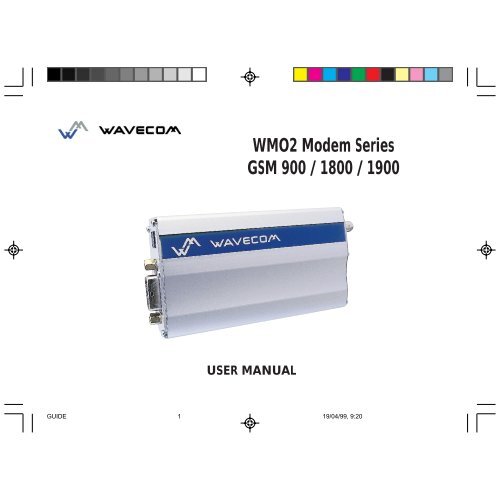
WMO2 Modem Series GSM 900 / 1800 / 1900 - Sierra Wireless, Inc.
WMO2 Modem Series GSM 900 / 1800 / 1900 - Sierra Wireless, Inc.
WMO2 Modem Series GSM 900 / 1800 / 1900 - Sierra Wireless, Inc.
- No tags were found...

Create successful ePaper yourself
Turn your PDF publications into a flip-book with our unique Google optimized e-Paper software.
SUMMARY1. PRODUCT DESCRIPTION 11.1 Package content 11.2 Product presentation 11.3 Physical characteristics 21.4 Functions - <strong>GSM</strong> Modes 21.5 Temperature range 22. INSTALLATION/START-UP 32.1 Mounting the modem 32.2 Installing the modem 32.3 Electrical characteristics 42.3.1 Switching the <strong>GSM</strong> modem on/off 42.3.2 Voltage range 42.3.3 Overvoltage/undervoltage 42.3.4 Power supply cable 52.3.5 Input/output electrical characteristics defined for all external connections 62.3.6 Protection/on-board network connection 63. DESCRIPTION OF THE INTERFACES 73.1 LED Function 73.2 Connectors 74. TECHNICAL DATA 11SUMMARYWavecom <strong>WMO2</strong> <strong>Modem</strong>GUIDE 219/04/99, 9:20
5. TROUBLESHOOTING: Specific defaults possibly encountered 125.1 The modem does not answer through the serial link 125.2 The modem always returns «Error» when trying to issue a communication 135.3 The modem always returns «No carrier» when trying to issue a communication 146. NOTES ON SAFETY 166.1 General safety 166.2 Vehicle safety 176.3 Car And Maintenance 176.4 Your responsibility 187. GENERAL INFORMATIONS 19SUMMARYWavecom <strong>WMO2</strong> <strong>Modem</strong>GUIDE 319/04/99, 9:20
1. PRODUCT DESCRIPTIONThe Wavecom <strong>WMO2</strong> modem exist under three different references:- <strong>WMO2</strong>-G<strong>900</strong> : <strong>GSM</strong> <strong>900</strong> MHz version- <strong>WMO2</strong>-G<strong>1800</strong> : <strong>GSM</strong> <strong>1800</strong> MHz version- <strong>WMO2</strong>-G1<strong>900</strong> : <strong>GSM</strong> 1<strong>900</strong> MHz version1.1 Package contentThe Wavecom <strong>WMO2</strong> modem package comprises:- 1 <strong>Modem</strong>- 2 holding bridles- 1 Power supply cable + fuse- 1 User manual (this document)1.2 Product presentationThe Wavecom <strong>WMO2</strong> modem is a terminal for fax and data transmission, short message service mobile originated, shortmessage service mobile terminated and voice calls.The connectors binded to the body guarantee output and input connections.An extractible holder is used to insert the SIM card (Micro-SIM type). A LED indicates the operating mode.PRODUCT DESCRIPTIONT MMicro-FitconnectorFront capSUB HDconnectorLEDBack capFigure 1<strong>Modem</strong> presentationSMAconnectorExtractibleSIM holderWavecom <strong>WMO2</strong> <strong>Modem</strong> 1GUIDE 419/04/99, 9:20
1.3 Physical characteristicsD imensions 98x54x25 mm (excluding connectors)Overalldimensions110x54x25 mmWeight< 140 gramsVolume13.23 cm3HousingAluminium profiled1.4 Functions - <strong>GSM</strong> ModesPRODUCT DESCRIPTIONStandard<strong>900</strong> MHz Class 4 (2W) - <strong>1800</strong> / 1<strong>900</strong> MHz Class 1 (1W) <strong>GSM</strong> Phase 2InterfaceSMSDataFaxSerial interface RS232 V.24/V.28 Autobauding functionAT command set based on V.25ter and <strong>GSM</strong> 07.05 & 07.07Mobile Originated (MO) and Mobile Terminated (MT).Mode Text & PDU point to point. Cell broadcast.In accordance with <strong>GSM</strong> 07.05.Asynchronous 2400, 4800, 9600 bits/s.Transparent and Non Transparent mode .In Non Transparent Mode only: 300, 1200, 1200/75 bauds.Mode 3.1 KHz (PSTN) and V110 (ISDN).2400/4800/7200/9600 bits/s<strong>GSM</strong> teleservice 62 in Transparent Mode.Class 1. Groupe 3 compatible.A udio FR + EFR - Accessories: 1 : Head set (future options) 2 : Car kit (future options )1.5 Temperature rangeOperating conditions : From -20°C to +55°CStorage conditions : From -25°C to +70°CWavecom <strong>WMO2</strong> <strong>Modem</strong> 2GUIDE 519/04/99, 9:20
2 INSTALLATION/START-UP2.1 Mounting the modemFor mounting the modem, bind to the body the holding bridles according to the schema below :Note:- To be attached to a plain surface- Screw head max. height: 2mmHolding bridles2.2 Installing the modemFigure 2<strong>Modem</strong> mountingTo install the modem, plug the device on a DC power supply (for automotive application,connect the device on the permanent « + » and insert the SIM card in the holder).Make sure that an antenna is connected.mm22mmINSTALLATION/START-UPIn order to extract or to insert the Micro SIM card, it is necessary to press the SIM holder ejector with a sharp element (a penfor example).If this sequence is not respected, the SIM holder could be damaged.Wavecom <strong>WMO2</strong> <strong>Modem</strong> 3GUIDE 619/04/99, 9:21
2.3 Electrical characteristics2.3.1 Switching the <strong>GSM</strong> modem on/offThe device is permanently powered (when connected to the power supply).2.3.2 Voltage rangeVoltage range : 5 to 32V DC (<strong>GSM</strong> <strong>900</strong>) - 6 to 32V DC (<strong>GSM</strong> <strong>1800</strong>/1<strong>900</strong>)GND : 0V2.3.3 Overvoltage/undervoltageINSTALLATION/START-UPCorrect operation of the Wavecom <strong>WMO2</strong> modem in communication mode is not guaranteed if input voltagefall below 5V (<strong>GSM</strong> <strong>900</strong>) - 6V (<strong>GSM</strong> <strong>1800</strong>/1<strong>900</strong>). The modem is protected against voltage over 32V.When input voltages exceed 32V, the supply voltage is disconnected in order to protect the electronic components from anovervoltage.TWO CASES ARE POSSIBLE:- IF THE OVERVOLTAGE IS CONTINUOUS, THE PROTECTION IS GUARANTEED BY THE FUSE.- IN THE CASE OF TRANSIENT PEAKS, THE MODEM GUARANTEES ITS OWN PROTECTION.Wavecom <strong>WMO2</strong> <strong>Modem</strong> 4GUIDE 719/04/99, 9:21
2.3.4 Power supply cableA cable, included in the package shall be used for power supply connection.The wires are marked as follows:Cable : 1 wireAme : tinned copper 24x0.2 mmSection : 0.75 mm 2 Figure 3T MConnector Molex Micro-Fit 3.0Side view-- + +Cables stripped over 200 mm, Stripped wire, tinned over 5 mmprotected by their own sheathStandard cable sheathPower supply cableINSTALLATION/START-UPWavecom <strong>WMO2</strong> <strong>Modem</strong> 5GUIDE 819/04/99, 9:21
2.3.5 Input/output electrical characteristics defined for all external connectionsINSTALLATION/START-UPPower supply:Parameters<strong>GSM</strong> <strong>900</strong><strong>GSM</strong> <strong>1800</strong>/1<strong>900</strong>M in. T yp.M ax.M in.T yp.Max.- Input supply voltage5 326 32V- Input supply voltage with Car Kit option1818V- Input peak supply current2.51 A- Inputaverage supply current in communication mode450200mA- Input average supply current in idle mode3035mASeriallink : - RS232Audio (head set) :- Microphone input current @2V/2KΩ 0.50.5mA- Absolute microphone input voltage100100mVp- Speaker output current 150Ω/ 1nF1616mA- Absolute speaker impedance3232ΩSIM3 or 53 or 5VUnit2.3.6 Protection/on-board network connectionThe modem is protected by a fuse directly binded on the power supply cable.Wavecom <strong>WMO2</strong> <strong>Modem</strong> 6GUIDE 919/04/99, 9:21
3. DESCRIPTION OF THE INTERFACESThe modem comprises several interfaces:- LED function indicating operating status- External antenna (via SMA)- Serial and control link (via 15 pins SUB D)- Power supply (via 4 pins Micro-Fit TM )- SIM card holder3.1 LED Function- LED off Device switched off - Not ready- LED on Device switched on - Connecting to network- LED flashing slowly Device switched on - Idle mode- LED flashing rapidly Device switched on - Transmission mode3.2 ConnectorsConnectorSMA15 pins SUB D(high density)TM4 pins Micro-FitFunctionRF antenna connectorRS232 linkAUDIO linkBOOTRESETPower supply connector« SIM »connectorSIM card connectionDESCRIPTION OF THE INTERFACESWavecom <strong>WMO2</strong> <strong>Modem</strong> 7GUIDE 1019/04/99, 9:21
Figure 4SMA connectorDESCRIPTION OF THE INTERFACESA SIM card is needed to operate on a <strong>GSM</strong> network.To install the card:- Press the yellow button to eject the holder.- Insert the SIM card.- Check that it fits into place correctly.ExtractibleSIM card holderSIM cardWavecom <strong>WMO2</strong> <strong>Modem</strong> 8SMA connector(antenna connector)Yellow button toeject the holder(with a sharp element)Figure 5SIM card holderGUIDE 1119/04/99, 9:21
Figure 615 pins SUB D connector(high density)5110615 11Pins assignment for15 pins SUB D ConnectorRS232AudioPINEIAWavecom <strong>WMO2</strong> <strong>Modem</strong> 9CCITDesignation1 DCD109Data Carrier Detect6 RX104Receive Data (out)2 TX103Transmit Data8 DTR108.2 Data Terminal Ready9 GND7 DSR0712RTS0511CTS0613RI254 MICROPHONE (+)5 MICROPHONE (-)10SPEAKER (+)15SPEAKER (-)Boot3 BOOTReset14RESETSignal ground1 Data Set Ready1 Request to send1 Clear to send1 Ring indicatorDESCRIPTION OF THE INTERFACESGUIDE 1219/04/99, 9:22
Figure 74 pins Micro-Fit TM connector1 23 41324DESCRIPTION OF THE INTERFACESConnector4 pinsMicro-Fit3.0TM123-4PinslayoutV+ BATTERYGROUNDAUXIThe 4 pins Micro-Fit 3.0 TM can be ordered from a supplier called MOLEX.The address can be obtained on the following internet site : www.wavecom.comCommentsPowersupplyNCWavecom <strong>WMO2</strong> <strong>Modem</strong> 10GUIDE 1319/04/99, 9:22
4. TECHNICAL DATADescriptionModule synchrocheckingReceiving anincoming callInitiate a callInitiate anemergency callCommunicationlossAT commandsModuleAT+CREG? CREG=,1CREG=,2CREG=,0ATARINGOKComments<strong>Modem</strong> synchronized on the networkSynchronization lost, re-synchronization attemptNetwork synchronization attemptAnswer the callA TD1234; Don't forget the « ; »at the end for « voice »callOKCommunication establishedC ME ERROR : 11PIN code not entered (with +CMEE : 1 mode)CME ERROR : 3AOC credit exceeded or a communication is already establishedA TD112; Don't forget the « ; »at the end for « voice »callOKNO CARRIERTECHNICAL DATAHang upEnter PIN CodeStore theparameters in E2PATHAT+CPIN=1234AT&WOKOKPIN Code accepted+ CME ERROR : 16<strong>Inc</strong>orrect PIN Code+ CME ERROR : 3PIN already entered (with +CMEE : 1 mode)OKThe configuration settings are stored in E2PWavecom <strong>WMO2</strong> <strong>Modem</strong> 11GUIDE 1419/04/99, 9:22
5. TROUBLESHOOTING: Specific defaults possibly encountered5.1 The modem does not answer through the serial linkA) Is the modem correctly powered on?❏ If not, the correct power supply is 5 to 32V (<strong>GSM</strong> <strong>900</strong>) - 6 to 32V (<strong>GSM</strong> <strong>1800</strong>/1<strong>900</strong>).B) Is the serial cable suitable and adjusted in the modem and PC sockets?❏ A suitable cable must follow pin assignment described on figure 6.❏ Check in particular, that Rx et Tx are properly connected.TROUBLESHOOTINGC) Check that your communication program is properly configured:❏ <strong>Modem</strong> factory setting for the character framing are:➫ Data Bits : 8➫ Parity : None➫ Stop Bits : 1❏The factory setting for baud rate is autobauding mode.D) Does any other program interfere with your communication program (conflict on communication port access)?❏ If yes, close any application likely to interfere (e.g. mouse or printer driver).Wavecom <strong>WMO2</strong> <strong>Modem</strong> 12GUIDE 1519/04/99, 9:22
5.2 The modem always returns «Error» when trying to issue a communicationA) Issue AT+CMEE=1 to have extended error cause and retryCausevalueDiagnostic0 PhonefailureCall your technical support3 Operation not allowed4 Operation not supported10SIM not inserted→ Insert the SIM card in the SIM holder of the modem,→ If SIM card is inserted, insure that it is properly inserted.11SIM PIN requiredEnter PIN code12S IM PUK requiredEnter PUK code (call your network provider if you don’ t know this code)13SIM Failure16<strong>Inc</strong>orrectpassword17SIM PIN2 required18SIM PUK2 requiredHintCheck validity of your SIM card. If SIM damaged, call your networkproviderCheck the code you enteredEnter PIN2 codeEnter PUK2 code (call your network provider if you don’code)26D ial string too longCheck your phone number (max 20 digits)30No network servicet know thisTROUBLESHOOTINGFor all other codes, and/or details, see AT commands manual.B) Additional hints❏ Is the modem registered on the network?Does the AT-Command AT + CREG? answers 0,1 (registered) or 0,5 (registered roaming)?➫ If not, check that the received signal is strong enough to synchronize on the Network (use AT+CSQ).Wavecom <strong>WMO2</strong> <strong>Modem</strong> 13GUIDE 1619/04/99, 9:22
❏ Is the modem receiving an incoming call or already in communication?➫ With some software versions, you must release any incoming or active call (with ATH) before being ableto make an outgoing call.5.3 The modem always returns «No carrier» when trying to issue a communicationA) After a failed attempt (“no carrier”), issue AT+CEER to have extended error causeCausevalueDiagnosticHintTROUBLESHOOTING1 Unallocated phone number16Normal call clearing17User busy18No user responding19User alerting, no answer21Call rejected22Number changed31Normal, unspecified50Requested facility not subscribed68ACM equal or greater than ACMmax252Call baring on outgoing callsCheck your subscription (data subscriptionavailable?)Credit of your pre-paid SIM card expired253Call baring on incoming calls3, 6, 8, 29, 34, 38, 41, 42,43, 44, 47, 49, 57, 58, 63,65, 69, 70, 79, 254Network causesFor all other codes, and/or details, see AT commands manual.See AT commands manual for further detailsor call network providerWavecom <strong>WMO2</strong> <strong>Modem</strong> 14GUIDE 1719/04/99, 9:22
B) Additional hints❏ Is the antenna properly connected?➫ For <strong>GSM</strong> <strong>900</strong> : use a 870 to 960 MHz / 50 Ohms antenna.➫ For <strong>GSM</strong> <strong>1800</strong> : use a 1710 to 1880 MHz / 50 Ohms antenna.➫ For <strong>GSM</strong> 1<strong>900</strong> : use a 1850 to 1990 MHz / 50 Ohms antenna.❏❏❏Is the received signal strong enough?➫ With the AT-Command AT+CSQ check that the received signal (1 st parameter of the response) is strongenough to be able to establish a call.AT+CSQ response(RSSI)* based on general observations.Signal quality11to 31 → Should be sufficient*0 to 10and +99→ Could be insufficient*The modem always returns «No carrier» when trying to issue a voice communication?➫ Insure the character «semicolon» is present straight after the phone number on the AT-CommandATD######;The modem always returns «No carrier» when trying to issue a data communication?➫ Insure the selected bearer type is supported by the called party.➫ Then, insure the selected bearer type is supported by the Network.➫ If no success, try bearer selection type: AT+CBST=0,0,3.➫ Insure the SIM Card is available for Data/Fax calls.TROUBLESHOOTINGWavecom <strong>WMO2</strong> <strong>Modem</strong> 15GUIDE 1819/04/99, 9:22
6. NOTES ON SAFETY6.1 General SafetyIt is important to follow any special regulations regarding the use of radio equipment due in particular to the possibility of radiofrequency, RF, interference. Please follow the safety advice given below carefully.❏ Switch OFF your <strong>GSM</strong> <strong>Modem</strong> when in an aircraft. The use of cellular telephones in an aircraft may endanger theoperation of the aircraft, disrupt the cellular network and is illegal. Failure to observe this instruction may lead to suspensionor denial of cellular telephone services to the offender, or legal action or both.❏ Switch OFF your <strong>GSM</strong> <strong>Modem</strong> when at a refueling point.NOTES ON SAFETY❏ Switch OFF your <strong>GSM</strong> <strong>Modem</strong> in hospitals and any other place where medical equipment may be in use.❏ Respect restrictions on the use of radio equipment in fuel depots, chemical plants or where blasting operations are inprogress.❏ There may be a hazard associated with the operation of your <strong>GSM</strong> <strong>Modem</strong> close to in adequately protected personalmedical devices such as hearing aids and pacemakers. Consult the manufactures of the medical device to determine if it isadequately protected.❏ Operation of your <strong>GSM</strong> <strong>Modem</strong> close to other electronic equipment may also cause interference if the equipment isinadequately protected. Observe any warning signs and manufacturers recommendations.Wavecom <strong>WMO2</strong> <strong>Modem</strong> 16GUIDE 1919/04/99, 9:22
6.2 Vehicle Safety❏ Do not use your <strong>GSM</strong> <strong>Modem</strong> while driving, unless equipped with a correctly installed vehicle kit allowing ‘Hands-Free’Operation.❏ Respect national regulations on the use of cellular telephones in vehicles. Road safety always comes first.❏ If incorrectly installed in a vehicle, the operation of <strong>GSM</strong> <strong>Modem</strong> telephone could interfere with the correct functioning ofvehicle electronics. To avoid such problems, ensure that the installation has been performed by a qualified personnel.Verification of the protection of vehicle electronics should form part of the installation.❏ The use of an alert device to operate a vehicle’s lights or horn on public roads is not permitted.6.3 Car And MaintenanceYour <strong>GSM</strong> <strong>Modem</strong> is the product of advanced engineering, design and craftsmanship and should be treated with care. Thesuggestion below will help you to enjoy this product for many years.❏ Do not expose the <strong>GSM</strong> <strong>Modem</strong> to any extreme environment where the temperature or humidity is high.❏ Do not attempt to disassemble the <strong>GSM</strong> <strong>Modem</strong>. There are no user serviceable parts inside.NOTES ON SAFETY❏ Do not expose the <strong>GSM</strong> <strong>Modem</strong> to water, rain or spilt beverages, It is not waterproof.❏ Do not abuse your <strong>GSM</strong> <strong>Modem</strong> by dropping, knocking, or violent shaking. Rough handling can damage it.❏ Do not place the <strong>GSM</strong> <strong>Modem</strong> alongside computer discs, credit or travel cards or other magnetic media. The informationcontained on discs or cards may be affected by the phone.Wavecom <strong>WMO2</strong> <strong>Modem</strong> 17GUIDE 2019/04/99, 9:22
❏ The use of third party equipment or accessories, not made or authorized by Wavecom may invalidate the warranty of <strong>GSM</strong><strong>Modem</strong>.❏ Do contact an authorized Service Center in the unlikely event of a fault.6.4 Your ResponsibilityThis <strong>GSM</strong> <strong>Modem</strong> is under your responsibility. Please treat it with care respecting all local regulations. It is not a toy thereforekeep it in a safe place at all times and out of the reach of children.Try to remember your Unlock and PIN codes. Become familiar with and use the security features to block unauthorized use andtheft.NOTES ON SAFETYWavecom <strong>WMO2</strong> <strong>Modem</strong> 18GUIDE 2119/04/99, 9:22
7. GENERAL INFORMATIONS<strong>GSM</strong> reference documents : <strong>GSM</strong> 03.40, <strong>GSM</strong> 03.45, <strong>GSM</strong> 04.11,<strong>GSM</strong> 04.21, <strong>GSM</strong> 05.08, <strong>GSM</strong> 07.01,<strong>GSM</strong> 07.02, <strong>GSM</strong> 07.05, <strong>GSM</strong> 07.07.ETSI contact : ETSI SecretariatF-06921 Sophia Antipolis Cedex, Francee-mail : secretariat@etsi.frService : The AT commands manual is avalable on Wavecom web site:http://www.wavecom.comDisclaimer<strong>Modem</strong> and <strong>GSM</strong>-unit specifications and manuals are subject to change without notice. Wavecom assumes no liability fordamage incurred directly or indirectly from errors, omissions or discrepancies between the modem or <strong>GSM</strong>-unit and theirmanuals.TrademarksSome mentioned products are registred trademarks of them respective companies.CopyrightThis manual is copyrighted by Wavecom with all rights reserved. No part of this manual may be reproduced in any form withoutthe prior written permission of Wavecom.No patent liability is assumed with respect to the use of the information contained herein.GENERAL INFORMATIONSWavecom <strong>WMO2</strong> <strong>Modem</strong> 19GUIDE 2219/04/99, 9:22
WAVECOM S.A. - 39 rue du Gouverneur Gal. Eboué, F-92130 Issy-les-Moulineaux - FranceTel: +33 1 46 29 08 00 - Fax: +33 1 46 29 08 08WAVECOM <strong>Inc</strong>. - 5405 Morehouse Drive, Suite 330 - San Diego, CA 92121 - USATel: +1 619 450 1778 - Fax: +1 619 450 1636WAVECOM Asia Pacific Ltd. - 2 nd floor, Shui On Center, 6/8 Harbour Road - Hong KongTel: +852 2824 8973 - Fax: +852 2824 8929GUIDE 2319/04/99, 9:23