
You also want an ePaper? Increase the reach of your titles
YUMPU automatically turns print PDFs into web optimized ePapers that Google loves.
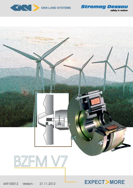
<strong>BZFM</strong> <strong>V7</strong><br />
449-00012 Version: - 21.11.2012<br />
GKN LAND SYSTEMS<br />
<strong>Stromag</strong> <strong>Dessau</strong><br />
safety in motion<br />
EXPECT MORE
<strong>BZFM</strong> <strong>V7</strong><br />
Electromagnetic Spring-Applied Brake<br />
Applications<br />
Holding- and working brake variations for general industry<br />
Usable for standard electric motors<br />
Standard Features<br />
Coil Body with coil : Thermal class 155 (F), special surface protection<br />
Armature disc : Special protection: nitrocarburated<br />
Brake disc : Special protection: nitrocarburated<br />
Friction lining carrier : Rigidly fixed on motor shaft via fitting key, zinc coated<br />
Friction lining : Axially flexible friction pads in the friction lining carrier allow a high tolerance<br />
when fixing friction lining carrier on the shaft thus simplifying the mounting<br />
on brake assembly.<br />
Adjusting Ring : A simple reduction of the brake torque up to a value of 55 % is possible.<br />
Adjusting screws : Several possible screws – type wear re-adjustment<br />
Fixings screws : Included in delivery, zinc coated<br />
Flying Leads : 0,5 metre long<br />
Optional Extra’s<br />
Micro switch to monitor switching states or wear monitoring (from size 6,3)<br />
Hand release lever<br />
Half wave rectifier<br />
Full wave rectifier<br />
Quick switching units<br />
GKN <strong>Stromag</strong> <strong>Dessau</strong> GmbH<br />
<strong>Dessau</strong>er Straße 10<br />
06844 <strong>Dessau</strong>-Roßlau<br />
www.stromag.<strong>com</strong><br />
Switching modules<br />
1 449-00012<br />
Version: -<br />
21.11.2012
Torque range 2,7 - 380 Nm<br />
<strong>BZFM</strong> <strong>V7</strong><br />
Electromagnetic Spring-Applied Brake<br />
Advantages<br />
Simple assembly to motor, no dismantling of brake required<br />
Completely pre-mounted and adjusted<br />
All surfaces are corrosion resistant<br />
Compact, simple construction with high heat capacity<br />
The fitted friction pads form an interrupted friction face thus resulting in good air circulation and<br />
heat dissipation.<br />
Less wear due to high stability of the friction material<br />
Delivered in run-in and torque tested condition<br />
Simple torque adjustment with adjusting ring<br />
As a standard, prepared for hand lever mounting – retrofit possible without any problems<br />
Free from axial loads when braking and running<br />
Suitable for vertical mounting, please consult GKN <strong>Stromag</strong> <strong>Dessau</strong> GmbH<br />
Proven reliable design<br />
Facilities to design to customer’s special requirements<br />
Protection IP 44 by rubber collar and seal ring on through-going shaft<br />
Voltages available<br />
Usual voltage: 24 V DC, 110 V DC, 190 V DC, 207 V DC and 240 V DC,<br />
Other voltages on request.<br />
Coils available to suit: AC – supplies with Half and Full wave rectification.<br />
We suggest the following alternative - Customer to take standard voltage with rectifier which GKN<br />
<strong>Stromag</strong> <strong>Dessau</strong> can provide.<br />
GKN <strong>Stromag</strong> <strong>Dessau</strong> GmbH<br />
<strong>Dessau</strong>er Straße 10<br />
06844 <strong>Dessau</strong>-Roßlau<br />
www.stromag.<strong>com</strong><br />
2 449-00012<br />
Version: -<br />
21.11.2012
<strong>BZFM</strong> <strong>V7</strong><br />
Electromagnetic Spring-Applied Brake<br />
Designation of individual <strong>com</strong>ponents<br />
01 Coil body 06 Coil<br />
02 Armature disc 07 Compression spring<br />
03 Brake disc 12 Adjusting ring<br />
04 Friction lining carrier 13 Seal ring<br />
05 Friction lining 14 Rubber collar<br />
Brake operation<br />
The brake <strong>BZFM</strong> <strong>V7</strong> is a spring loaded electromagnetic double-face brake which brakes without current<br />
and is released electromagnetically.<br />
The coil body (01) contains a coil (06) which is potted with a synthetic resin <strong>com</strong>pound in accordance<br />
with thermal class 155, (max. limit of temperature 155 ◦ C).<br />
If the coil (06) is not excited, the springs (07) which are situated in the internal and external pole,<br />
press the armature disc (02) against the floating formatted friction lining carrier (04). Thus is firmly<br />
clamped between the torsion-protected armature disc (02) and the brake disc (03) and thus prevented<br />
from rotating. The braking effect is transmitted from the friction lining via the carrier with friction<br />
lining (04) and a feather key to the shaft. If the coil (06) is connected to a direct voltage as specified on<br />
the identification plate or about a <strong>Stromag</strong> rectifier set to a alternating voltage, the magnetic force will<br />
draw the armature disc (02) to the coil body (01) against the spring pressure (07). The friction lining is<br />
released, the braking is cancelled and the brake is released.<br />
GKN <strong>Stromag</strong> <strong>Dessau</strong> GmbH<br />
<strong>Dessau</strong>er Straße 10<br />
06844 <strong>Dessau</strong>-Roßlau<br />
www.stromag.<strong>com</strong><br />
3 449-00012<br />
Version: -<br />
21.11.2012
Micro Switch<br />
<strong>BZFM</strong> <strong>V7</strong><br />
Electromagnetic Spring-Applied Brake<br />
Standard option available from size 6,3 up to 25, Inboard Proving Switch, one <strong>com</strong>mon contact,<br />
one normally open contact and one normally closed contact. This can be interlocked with motor<br />
contactor for parking brake duty, i.e. brake release before starting motor.<br />
Brake termination<br />
Flyaway leads, usually 0,5 meter long.<br />
Emergency release by means of hand lever release<br />
Optionally the brake can be equipped with a hand release lever allowing the manual release by means<br />
of a hand lever. The brake is prepared for hand lever mounting – retrofit is possible without any<br />
problems.<br />
Brake flange<br />
Counter-friction face mounted to the motor on B-side.<br />
Adjusting ring<br />
A simple reduction of the brake torque up to a value of 55 % is possible.<br />
Adjusting screws<br />
The air gap of the brake can be re-adjusted several times until the lower wear limit of them friction<br />
lining is achieved.<br />
List of dimensions<br />
Tabelle 1: technical data<br />
Size MSN M Ü n0 nzn airgap min/max W Pvn J m<br />
<strong>BZFM</strong> <strong>V7</strong> Nm Nm min −1 min −1 mm kJ kW kgm 2 kg<br />
0,25 2,7 3 3600 2900 0,25 / 0,4 4 0,01 0,00004 1,5<br />
0,63 5,7 6,25 3600 2900 0,3 / 0,5 6 0,015 0,00009 2,1<br />
1,6 12,5 13,5 3600 2900 0,3 / 0,5 9 0,02 0,00020 3,0<br />
2,5 24,5 27 3600 2900 0,3 / 0,5 13 0,028 0,00030 5,0<br />
4 33,6 37 3600 2900 0,3 / 0,6 16 0,033 0,00046 6,3<br />
6,3 59 65 3600 2900 0,4 / 0,7 22 0,046 0,00070 9,3<br />
10 113 125 3600 2900 0,4 / 0,7 32 0,09 0,00250 14,8<br />
16 220 250 3600 2900 0,4 / 0,7 48 0,11 0,00450 22,0<br />
25 345 380 3600 1450 0,4 / 0,7 60 0,14 0,00870 31,6<br />
GKN <strong>Stromag</strong> <strong>Dessau</strong> GmbH<br />
<strong>Dessau</strong>er Straße 10<br />
06844 <strong>Dessau</strong>-Roßlau<br />
www.stromag.<strong>com</strong><br />
4 449-00012<br />
Version: -<br />
21.11.2012
<strong>BZFM</strong> <strong>V7</strong><br />
Electromagnetic Spring-Applied Brake<br />
MSN : switchable nominal torque at 1m/s frictional speed to DIN VDE 0580 (applies<br />
to dry operation with an oil- and grease-free friction lining after running-in)<br />
M Ü : transmissible static nominal torque without slip, to DIN VDE 0580 (applies to<br />
dry operation with an oil- and grease-free friction lining after running-in)<br />
n0 : maximum idling speed<br />
nzn : admissible switching speed<br />
Pk : excitation output at 20 ◦ C<br />
Pvn : nominal braking capacity (S4-40 % I.O.)<br />
W : switch work per switching operation for z = 1 − 5h −1<br />
J : mass moment of inertia of rotating parts<br />
m : weight<br />
mode of operation : S1, S2, S4-40 % I.O.<br />
thermal class : 155 (F) in accordance with DIN VDE 0580.<br />
AC-control : via rectifier<br />
GKN <strong>Stromag</strong> <strong>Dessau</strong> GmbH<br />
<strong>Dessau</strong>er Straße 10<br />
06844 <strong>Dessau</strong>-Roßlau<br />
www.stromag.<strong>com</strong><br />
5 449-00012<br />
Version: -<br />
21.11.2012
Size<br />
<strong>BZFM</strong> <strong>V7</strong><br />
<strong>BZFM</strong> <strong>V7</strong><br />
Electromagnetic Spring-Applied Brake<br />
Tabelle 2: table of dimensions (all dimensions in mm)<br />
0.25 0.63 1.6 2.5 4.0 6.3 10 16 25<br />
d1min (H7) 10 10 15 15 20 25 32 40 40<br />
d1bevorzugt (H7) 11/12 12/15 16/20 20/22 22/25 30/32 35/38/40 45/48 45/50/55<br />
d1max (H7) 12 15 22 25 28 35 45 50 60<br />
d3 48 55 64 73 80 86 98 115 134<br />
d4 (H7) 91 106 118 136 152 166 193 224 262<br />
d6 (H7) 74,5 89 100 116 130 144 164 194 228<br />
d7 M4 M4 M4 M5 M6 M6 M10 M10 M12<br />
d10 85 100 112 130 146 160 185 216 254<br />
d11 (H9) 28 40 50 55 65 80 65 95 130<br />
d14 73 87,5 100 116 130 144 162 196 228<br />
d15 M4 M4 M4 M6 M6 M6 M10 M10 M12<br />
d16 4,3 4,3 4,3 5,4 6,4 6,4 10,25 10,25 12,2<br />
d17 85 100 112 130 146 160 185 216 254<br />
L1 20 20 20 25 30 30 35 40 50<br />
L2 1,5 1,5 1,5 1,8 1,8 1,8 2,0 2,0 2,0<br />
L3 36,2 37,7 44,7 53,6 56,5 62,9 82,2 90,2 92,4<br />
L4 44,7 46,2 53,2 64,4 68,3 74,6 96 106 109<br />
L5 26 26 26 32 32 34 52 52 52<br />
L7 ∗ (ca.) 6 5,9 7,2 8,2 8,2 9,6 8,4 8,4 7,3<br />
L8 7 7 7 9 10 10 11,5 13,5 14,5<br />
L9 6 6,3 6,8 11,6 12 9,3 14 23 14,6<br />
L12 95 109,5 122 144 162 176 210 247 294<br />
Kabellänge 400 425 480 550 585 615 560 650 790<br />
Tabelle 3: electrical data apply to DC (other voltages on request)<br />
Size UN = 24V UN = 103V UN = 190V UN = 207V UN = 240V<br />
<strong>BZFM</strong> <strong>V7</strong> PK[W ] PK[W ] PK[W ] PK[W ] PK[W ]<br />
0,25 20 16 23 22 24<br />
0,63 23 20 26 25 27<br />
1,6 32 13,5 37 35 36<br />
2,5 40 27 43 41 44<br />
4 48 37 59 56 60<br />
6,3 65 65 74 70 75<br />
10 83 86 92 91 94<br />
16 102 100 123 114 125<br />
25 142 123 135 127 133<br />
GKN <strong>Stromag</strong> <strong>Dessau</strong> GmbH<br />
<strong>Dessau</strong>er Straße 10<br />
06844 <strong>Dessau</strong>-Roßlau<br />
www.stromag.<strong>com</strong><br />
6 449-00012<br />
Version: -<br />
21.11.2012
Size<br />
<strong>BZFM</strong> <strong>V7</strong><br />
<strong>BZFM</strong> <strong>V7</strong><br />
Electromagnetic Spring-Applied Brake<br />
Tabelle 4: table of dimensions for hand release lever (all dimensions in mm)<br />
0.25 0.63 1.6 2.5 4.0 6.3 10 16 25<br />
L10 31 33 39 46,5 49,5 54,7 14,5 10,5 11,5<br />
L11 113,5 120,5 126 154 162 169 420 440 460<br />
L13 48,5 55,5 61 74 82 89 100 122,5 147,5<br />
L14 6 6 6 8 8 8 10 12,5 12,5<br />
L15 8 8 8 10 10 10 14 14 14<br />
β 6 ◦ 7 ◦ 7 ◦ 5 ◦ 5,5 ◦ 6 ◦ 7,4 ◦ 6 ◦ 6,4 ◦<br />
GKN <strong>Stromag</strong> <strong>Dessau</strong> GmbH<br />
<strong>Dessau</strong>er Straße 10<br />
06844 <strong>Dessau</strong>-Roßlau<br />
www.stromag.<strong>com</strong><br />
7 449-00012<br />
Version: -<br />
21.11.2012
<strong>BZFM</strong> <strong>V7</strong><br />
Electromagnetic Spring-Applied Brake<br />
Example of designation<br />
Calculations<br />
Abbildung 1: The diagram shows the time response of an electromagnetic spring - applied brake as defined by the VDE<br />
regulations 0580<br />
GKN <strong>Stromag</strong> <strong>Dessau</strong> GmbH<br />
<strong>Dessau</strong>er Straße 10<br />
06844 <strong>Dessau</strong>-Roßlau<br />
www.stromag.<strong>com</strong><br />
8 449-00012<br />
Version: -<br />
21.11.2012
M1 = switchable torque [Nm]<br />
<strong>BZFM</strong> <strong>V7</strong><br />
Electromagnetic Spring-Applied Brake<br />
The switchable (dynamic) torque is the torque which can be transmitted by a brake under slip condition<br />
depending on the friction coefficient and at working temperature. (M1 = 0, 9MSN)<br />
M3 = synchronization torque [Nm]<br />
The synchronization torque is the torque which arises for a short time after finishing the switching process .<br />
M Ü<br />
= transmissible torque [Nm]<br />
The transmissible (static) torque is the max. torque that can be applied to a brake without the risk of<br />
slipping.<br />
MSN = switchable nominal torque [Nm]<br />
The switchable nominal torque is the dynamic torque as stated in the catalogue at a frictional speed of 1<br />
m/sec.<br />
ML = load torque [Nm]<br />
+ML for acceleration, −ML for deceleration. The load torque should always be considered with relative<br />
safety factors.<br />
M5 = no - load torque (drag torque) [Nm]<br />
The no - load torque is the torque which the brake transmits at working temperature when free running.<br />
MA = decelerating torque [Nm]<br />
The decelerating torque results from the addition (substraction for lifting gear during lowering) of the switchable<br />
torque and load torque.<br />
Operation times<br />
The operation times shown in the diagram are based on the example of a brake actuated by loss of electrical<br />
current. The basic characteristic is also applicable to brakes with alternate methods of operation.<br />
The time delay t11 is the time from the instant of de - energization (actuation) to the <strong>com</strong>mencement<br />
of the torque build - up (of no importance for d.c. switching). The torque build - up time t12 is the time<br />
from the <strong>com</strong>mencement of torque build - up to the attainment of 90% of the switchable nominal torque<br />
MSN. The switching time t1 is the sum of the time delay and torque build - up time:<br />
t1 = t11 + t12<br />
The time delay t21 is the time from energization (actuation) to the <strong>com</strong>mencement of the torque will decrease.<br />
The fall time t22 is the time from the <strong>com</strong>mencement of the torque decrease to 10% of the switchable nominal<br />
brake torque MSN. The switching time t2 is the sum of the time delay and the fall time:<br />
t2 = t21 + t22<br />
To decrease the switching times of electromagnetic spring - applied brakes, special switching is required.<br />
Please ask for particular information. The switching times stated in the dimensional tables apply to d.c.<br />
switching, working temperature and nominal voltage without special switching techniques.<br />
GKN <strong>Stromag</strong> <strong>Dessau</strong> GmbH<br />
<strong>Dessau</strong>er Straße 10<br />
06844 <strong>Dessau</strong>-Roßlau<br />
www.stromag.<strong>com</strong><br />
9 449-00012<br />
Version: -<br />
21.11.2012
Nomenclature<br />
AR cm 2 Friction surface<br />
m kg Mass<br />
Q Joule(J) Heat quantity<br />
Qh W att(W ) Heat per hour<br />
c<br />
kJ<br />
kgK<br />
n rpm Speed<br />
tA s Braking time<br />
tS s Slipping time<br />
Mass moment of inertia J [kgm 2 ]<br />
<strong>BZFM</strong> <strong>V7</strong><br />
Electromagnetic Spring-Applied Brake<br />
Specific heat steel c = 0, 46 kJ<br />
kgK<br />
cast iron c = 0, 54 kJ<br />
kgK<br />
The mass moment of inertia J stated in the formula is the total mass moment of inertia of all the masses<br />
to be retarded referred to the brake.<br />
Reduction of moments of inertia<br />
The reduction of moments of inertia is calculated from the formula<br />
Moments of inertia of linear masses<br />
J1 = J2 ∗ ( n2<br />
) 2<br />
n1<br />
[kgm 2 ]<br />
The equivalent moment of inertia JErs for a linear mass m and a velocity v referred to the brake speed n<br />
is calculated from the formula<br />
Torque considerations for the brake<br />
JErs = 91 ∗ m( v<br />
n )2 [kgm2 ]<br />
[v = m/s] [n = rpm] [m = kg]<br />
The mean torque of the driving or driven machine may be calculated from<br />
M = 9550 ∗ P<br />
n<br />
[Nm]<br />
[P = kW ] [n = rpm]<br />
If the system includes gearing, all torques must be referred to the brake shaft. Depending on the type<br />
and functioning of the driving or driven machine resp. shock and peak loads are an important factor for<br />
the determination of brake sizes. If precise deceleration times are required a sufficient decelerating torque<br />
must already been taken into account when selecting the brake size on the torque rating. Considering the<br />
load torque direction, the following switchable nominal torque MSN of a brake is attained (+ML for lifting<br />
devices when lowering).<br />
GKN <strong>Stromag</strong> <strong>Dessau</strong> GmbH<br />
<strong>Dessau</strong>er Straße 10<br />
06844 <strong>Dessau</strong>-Roßlau<br />
www.stromag.<strong>com</strong><br />
MSN = MA ± ML<br />
10 449-00012<br />
Version: -<br />
21.11.2012
<strong>BZFM</strong> <strong>V7</strong><br />
Electromagnetic Spring-Applied Brake<br />
When expressing the decelerating torque MA by means of the pulse principle, we obtain after corresponding<br />
conversion<br />
MA = J ∗ dω<br />
dt<br />
J ∗ n<br />
MSN =<br />
9, 55 ∗ ta<br />
tA =<br />
± ML<br />
J ∗ n<br />
9, 55 ∗ (MSN ± ML)<br />
[Nm]<br />
It is assumed that the dynamic torque is achieved instantaneously.<br />
Considerations of dissipated energy<br />
For all operations at speed with slip, dissipated energy is generated in the brake which is transformed into<br />
heat. The admissible amount of dissipated energy resp. power capacity must not be exceeded in order to<br />
avoid any inadmissible heating. Often the selection of the brake size upon the torque requirement only is<br />
not sufficient. Therefore it must always be checked whether the heat capacity of the brake is sufficient.<br />
Generally the dissipated energy in a brake, slipping at time dt with its dynamic torque MS at an angular<br />
speed ωS is:<br />
dQ = MS ∗ ωS ∗ dt<br />
[Nm]<br />
With ωS and conversion by means of the pulse principle the following dissipated energy amount is determined<br />
for a single deceleration process with existing load torque<br />
Q =<br />
MSN<br />
MSN ± ML<br />
∗<br />
J ∗ n2<br />
182000<br />
(−ML for lifting gears during lowering)<br />
If a brake slips with constant slipping speed under operation, the dissipated energy is calculated from the<br />
formula<br />
Q = 0, 105 ∗ 10 −3 ∗ MS ∗ nS ∗ tS<br />
Working brake:<br />
The brake has to brake a shaft with switching frequency ”X”from speed ”Y”to speed zero and has to hold it.<br />
Holding brake with emergency stop function:<br />
The brake actuates with shaft speed zero and has to hold; in case of emergency, however, it must be able<br />
to brake from shaft speed ”Y”to zero.<br />
GKN <strong>Stromag</strong> <strong>Dessau</strong> GmbH<br />
<strong>Dessau</strong>er Straße 10<br />
06844 <strong>Dessau</strong>-Roßlau<br />
www.stromag.<strong>com</strong><br />
[s]<br />
[kJ]<br />
[kJ]<br />
11 449-00012<br />
Version: -<br />
21.11.2012
<strong>BZFM</strong> <strong>V7</strong><br />
Electromagnetic Spring-Applied Brake<br />
Permissible Heat Capacity at 3000 rpm<br />
W [kJ] Switching operations z [ 1<br />
] operations per hour<br />
h<br />
Abbildung 2: Heat capacity of series <strong>BZFM</strong> <strong>V7</strong> n = 3000 rpm **. By known operations and number of operations per hour<br />
the brake size can be obtained.<br />
Example: W = 10 kJ/operation und z = 10 operations/hour Size <strong>BZFM</strong> 1.6 <strong>V7</strong><br />
** permissible switching operations per switching at other speed ratings on request<br />
GKN <strong>Stromag</strong> <strong>Dessau</strong> GmbH<br />
<strong>Dessau</strong>er Straße 10<br />
06844 <strong>Dessau</strong>-Roßlau<br />
www.stromag.<strong>com</strong><br />
12 449-00012<br />
Version: -<br />
21.11.2012
<strong>BZFM</strong> <strong>V7</strong><br />
Electromagnetic Spring-Applied Brake<br />
Questionnaire to allow the determination of spring applied brakes<br />
DRIVING MACHINE<br />
Frequency controlled motor<br />
Pole changing motor<br />
Constant speed motor<br />
Other motor types<br />
Nominal and maximum power kW<br />
Nominal and maximum speed rpm<br />
Maximum torque (i.e. breakdown torque) Nm<br />
DRIVEN MACHINE<br />
Slewing system<br />
Hoisting system<br />
Trolley or gantry system<br />
Winch system<br />
People transporting system<br />
Other application<br />
BRAKE TYPE GENERALLY<br />
Working and emergency brake<br />
Holding brake with emergency characteristic<br />
CALCULATION DATA<br />
Nominal braking speed rpm<br />
Emergency braking speed (i.e. max. possible overspeed at hoisting drives) rpm<br />
Load torque at nominal braking speed Nm<br />
Load torque at emergency braking speed Nm<br />
Maximum possible load torque Nm<br />
Number of braking operations per hour at nominal / required speed<br />
(incl. load data)<br />
Number of braking operations per required time unit at emergency speed<br />
(incl. maximum load data)<br />
Moment of inertia of the parts moved by the motor or braked by the brake kgm 2<br />
(motor, gearbox, winch etc.)<br />
Demanded switching cycles of the brake<br />
Ambient temperature<br />
Protection class or short description of environmental conditions<br />
Marine, port, in house<br />
Options<br />
Microswitch, rectifier, switching unit, terminal box, heater or other<br />
GKN <strong>Stromag</strong> <strong>Dessau</strong> GmbH<br />
<strong>Dessau</strong>er Straße 10<br />
06844 <strong>Dessau</strong>-Roßlau<br />
www.stromag.<strong>com</strong><br />
13 449-00012<br />
Version: -<br />
21.11.2012<br />
◦ C
GKN LAND SYSTEMS<br />
GKN <strong>Stromag</strong> <strong>Dessau</strong> GmbH<br />
<strong>Dessau</strong>er Str. 10<br />
06844 <strong>Dessau</strong>-Roßlau<br />
Tel.: +49 (340) 2190-203<br />
Fax: +49 (340) 2190-201<br />
E-Mail: vertrieb.str105@gkn.<strong>com</strong><br />
Internet: http://www.stromag.<strong>com</strong><br />
<strong>Stromag</strong> <strong>Dessau</strong><br />
OUR ADDRESS<br />
safety in motion<br />
ONE TEAM IN MOTION