PTT Periflex mehr Drehmoment und sicher couple élevé ... - Gkn.com
PTT Periflex mehr Drehmoment und sicher couple élevé ... - Gkn.com
PTT Periflex mehr Drehmoment und sicher couple élevé ... - Gkn.com

You also want an ePaper? Increase the reach of your titles
YUMPU automatically turns print PDFs into web optimized ePapers that Google loves.
safety in motion<br />
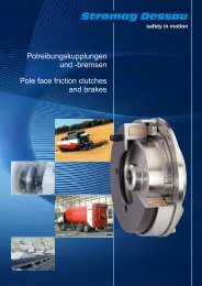
<strong>PTT</strong><br />
Perifl ex ®<br />
Top Torque<br />
Wellenkupplung<br />
<strong>mehr</strong> <strong>Drehmoment</strong><br />
<strong>und</strong> <strong>sicher</strong><br />
<strong>couple</strong> <strong>élevé</strong><br />
et sûr<br />
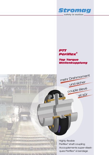
Highly-fl exible<br />
Perifl ex ® shaft coupling<br />
Ac<strong>couple</strong>ments super-élastiques<br />
Perifl ex ® à bandage
<strong>Periflex</strong>® − Top Torque<br />
Katalog Nr. D 801<br />
Alle Angaben über <strong>Periflex</strong>® − Top Tor−<br />
que in Druckschriften älteren Datums<br />
sind mit dem Erscheinen dieser Druck−<br />
schrift nur noch bedingt gültig.<br />
Maß − <strong>und</strong> Konstruktionsänderungen<br />
behalten wir uns vor.<br />
Stromag − Produkte entsprechen dem<br />
Qualitätsstandard nach DIN ISO<br />
9001.<br />
Inhalt Seite<br />
Das <strong>Periflex</strong>® − Top Torque − Konzept<br />
ATEX − Richtlinie 2<br />
Hinweise für den Konstrukteur<br />
Klassifikationsvorschriften<br />
Anwendungsfaktor 3 − 5<br />
Montagehinweise <strong>und</strong> Lieferumfang<br />
Hinweise zur Auswahl der<br />
Kupplungsgröße 6 − 7<br />
Lagerung von gummielastischen<br />
Elementen, Bestellbeispiel<br />
Anzugsmomente der Schrauben 8<br />
Kennwerte der<br />
<strong>Periflex</strong> � − Top Torque 9 − 13<br />
Zuordnung an E − Motore 14<br />
Leistungstabellen 15 − 16<br />
Baureihe <strong>PTT</strong> 17 − 18<br />
Umrechnungsfaktoren 19<br />
Fragebogen 20<br />
ATEX 95 − Konformität 21 − 24<br />
Catalogue No. D 801<br />
This catalogue for Stromag <strong>Periflex</strong>® −<br />
Top Torque cancels and replaces all for−<br />
mer editions.<br />
We reserve the right to modify the di−<br />
mensions and constructions.<br />
Stromag products <strong>com</strong>ply with the<br />
Quality Standard to DIN ISO 9001.<br />
Content Page<br />
The <strong>Periflex</strong>® − Top Torque principle<br />
Regulation ATEX 2<br />
Hints for the designer<br />
Classification regulations<br />
Application factor 3 − 5<br />
Hints for selection of the<br />
coupling size<br />
Mounting hints and delivery extent6 − 7<br />
Storing of rubber flexible elements<br />
Example for ordering<br />
Wrench torque of the screws 8<br />
Characteristics of<br />
<strong>Periflex</strong> � − Top Torque 9 − 13<br />
Co − ordination to electric motors 14<br />
Output tables 15 − 16<br />
Series <strong>PTT</strong> 17 − 18<br />
Conversion Factors 19<br />
Questionnaire 20<br />
ATEX 95 − Conformity 21 − 24<br />
1<br />
Catalogue n. D 801<br />
Le présent catalogue pour ac<strong>couple</strong>−<br />
ments <strong>Periflex</strong>® − Top Torque annule et<br />
remplace les éditions antérieures.<br />
Nous nous réservons le droit d’apporter<br />
toutes modifications de constructions et<br />
dimensions.<br />
Les produits Stromag répondent aux<br />
exigences de qualité de la norme DIN<br />
ISO 9001.<br />
Sommaire Page<br />
Le principe du <strong>Periflex</strong>® − Top<br />
Torque, Directive ATEX 2<br />
Re<strong>com</strong>mandations pour l’utilisateur<br />
Prescriptions de classification<br />
Facteurs de service 3 − 5<br />
Sélection ac<strong>couple</strong>ment<br />
Montage et fourniture 6 − 7<br />
Stockage des éléments élastiques<br />
Exemple de <strong>com</strong>mande<br />
Couples de serrage des vis 8<br />
Caractéristiques du<br />
<strong>Periflex</strong>® − Top Torque 9 − 13<br />
Présélection pour moteurs<br />
électriques 14<br />
Tableaux des caractéristiques 15 − 16<br />
Série <strong>PTT</strong> 17 − 18<br />
Facteurs de conversion 19<br />
Questionnaire 20<br />
Conformité ATEX 95 21 − 24<br />
Datum / Date 12.2005
<strong>Periflex</strong>® − Top Torque<br />
Das <strong>Periflex</strong> � − Top Torque − Konzept<br />
Die Stromag <strong>Periflex</strong>® − Top Torque ist<br />
eine hochelastische Gummi − Gewebe −<br />
Kupplung, besonders geeignet für die<br />
Verbindung zweier Wellen in dieselmo−<br />
torischen <strong>und</strong> elektrischen Antrieben.<br />
Die Baureihe erstreckt sich über den<br />
<strong>Drehmoment</strong>bereich von 35 − 20460<br />
Nm.<br />
Die <strong>Periflex</strong>® − Top Torque<br />
entspricht den Anforderungen der<br />
Richtlinie 94/9/EG (ATEX 95) der Gerä−<br />
tegruppe II, Gerätekategorie 2G bzw.<br />
2D (Zone 1) <strong>und</strong> Temperaturklasse T4.<br />
Die <strong>Periflex</strong>® − Top Torque ist auch mit<br />
Abnahme nach EN 10204 gem. den<br />
Vorschriften der Klassifikationsgesell−<br />
schaften lieferbar.<br />
Die <strong>Periflex</strong>® − Top Torque kann wegen<br />
der besonderen Ausbildung des Wel−<br />
lenreifens extrem große Verlagerungen,<br />
bei geringen Rückstellkräften, in jeder<br />
Richtung aufnehmen, s. Liste techni−<br />
sche Daten, ohne daß sich das als Ver−<br />
schleiß bemerkbar macht. Der Reifen ist<br />
durch eine werkseitige Trennfuge stan−<br />
dardmäßig radial montierbar <strong>und</strong> de−<br />
montierbar, ohne Verschieben der ver−<br />
b<strong>und</strong>enen Maschinen.<br />
Die Übertragung des <strong>Drehmoment</strong>es<br />
mit der <strong>Periflex</strong>® − Top Torque erfolgt<br />
absolut spielfrei. Sie ist geeignet zur<br />
Aufnahme von <strong>Drehmoment</strong>stößen <strong>und</strong><br />
dämpft auftretende Schwingungen.<br />
Datum / Date 12.2005<br />
The <strong>Periflex</strong> � − Top Torque Principle<br />
The Stromag <strong>Periflex</strong>® − Top Torque is<br />
a highly − flexible rubber fabric coupling,<br />
in particular suitable to link two shafts in<br />
diesel − engine and electric drives.<br />
The torque range of this series is 35 Nm<br />
to 20460 Nm.<br />
The <strong>Periflex</strong>® − Top Torque<br />
meets the requirements of regulation<br />
94/9/EG (ATEX 95) of the device group<br />
II, device category 2G or 2D (Zone 1)<br />
and temperature class T4.<br />
The <strong>Periflex</strong>® − Top Torque can also be<br />
supplied with survey to EN 10204 as<br />
per the prescriptions of the classification<br />
societies.<br />
Due to the special form of the shaft tyre,<br />
the <strong>Periflex</strong>® − Top Torque is able to<br />
<strong>com</strong>pensate extremely large offsets in<br />
every direction (with low restoring for−<br />
ces) without generating wear, see list of<br />
technical data. In the works the tyre is<br />
provided with a parting line as a stan−<br />
dard thus allowing the radial mounting<br />
and dismantling without having to shift<br />
the connected machines.<br />
With the <strong>Periflex</strong>® Top Torque the torque<br />
transmission is absolutely free from<br />
backlash. It is suitable to absorb torque<br />
peaks and damps occurring vibrations.<br />
2<br />
Le principe du <strong>Periflex</strong>® − Top Torque<br />
Le <strong>Periflex</strong>® − Top Torque est un accou−<br />
plement super − élastique à bandage<br />
caoutchouc armé de tissus assurant la<br />
liaison entre deux arbres de machines<br />
travaillant dans le prolongement l’une<br />
de l’autre (entraînement par moteur die−<br />
sel ou électrique).<br />
Plage de <strong>couple</strong>s allant de 35 Nm à<br />
20460 Nm.<br />
Le <strong>Periflex</strong>® − Top Torque<br />
répond aux exigences de la directive<br />
94/9/EG (ATEX 95) groupe II, catégorie<br />
2G ou 2D (zone 1) et classe de<br />
température T4.<br />
Le <strong>Periflex</strong>® − Top Torque peut aussi<br />
être livré suivant EN 10204 selon les<br />
règlements des sociétés de classifica−<br />
tion.<br />
La conception du bandage permet<br />
d’accepter des désalignements impor−<br />
tants tout en limitant les réactions sur le<br />
palier des machines accouplées et<br />
donc l’usure prématurée (voir caractéri−<br />
stiques techniques). Pour permettre le<br />
montage et le démontage sans dépla−<br />
cement des machines, le bandage est<br />
coupé dans le sens de rotation.<br />
Le <strong>Periflex</strong>® − Top Torque transmet le<br />
<strong>couple</strong> et est absolument libre de tout<br />
jeu. Il absorbe les à − coups et amortit<br />
les vibrations.
<strong>Periflex</strong>® − Top Torque<br />
Hinweise für den Konstrukteur<br />
Die Kupplungsnaben sowie die Druck−<br />
ringe sind aus Stahl <strong>und</strong> haben eine<br />
Korrosionsschutz− Schicht. Die Schrau−<br />
ben sind aus der Stahlsorte A4 <strong>und</strong> ver−<br />
hindern somit das Festrosten im Ge−<br />
winde. Der Wellenreifen ist aus<br />
Naturkautschuk mit Gewebeeinlagen,<br />
die in radialer oder in diagonaler Aus−<br />
richtung eingelegt sind. Durch die Art<br />
der Gewebeanordnung werden unter−<br />
schiedliche Drehfedersteifen realisiert.<br />
Wellenreifen in flammwidriger, elektrisch<br />
isolierender <strong>und</strong> ölbeständiger Ausfüh−<br />
rung sind auf Anfrage lieferbar.<br />
Der Wellenreifen ist standardmäßig<br />
durch die werkseitig vorgesehene<br />
Trennfuge radial montierbar, kann aber<br />
zur besseren Montage auch in zwei ge−<br />
wichtsgleiche Teile getrennt werden,<br />
ohne daß das übertragbare Drehmo−<br />
ment reduziert werden muß.<br />
Die <strong>Periflex</strong> � − Top Torque entwickelt<br />
unter dem Einfluß von <strong>Drehmoment</strong><br />
<strong>und</strong> Drehzahl eine bestimmte Axialkraft,<br />
die durch eine geeignete Lagerung auf−<br />
genommen werden muß. Zur eigenen<br />
Bestimmung der auftretenden Ax−<br />
ialkräfte ist bei der Stromag AG die<br />
technische Unterlage "Ermittlung der re−<br />
sultierenden Axialkräfte F A" anzufor−<br />
dern.<br />
Hints for the designer<br />
The coupling hubs and the pressure<br />
rings are made of steel and are provi−<br />
ded with a protection layer against<br />
corrosion. The screws are made of steel<br />
type A4 thus preventing the rusting in<br />
the thread. The shaft tyre material is na−<br />
tural rubber containing fabric inserts<br />
which are inserted radially or transver−<br />
sally. The various possibilities of fabric<br />
arrangement allow to realize different<br />
torsional spring stiffnesses.<br />
Shaft tyres in non − flammable, electri−<br />
cally insulating and oil − resistant execu−<br />
tion are available on request.<br />
The shaft tyre can be mounted radially<br />
(standard) due to the parting line provi−<br />
ded in the works; to simplify the moun−<br />
ting, however, it can be separated in<br />
two equiweighed parts without having<br />
to reduce the transmittable torque.<br />
Influenced by the torque and the speed,<br />
the <strong>Periflex</strong> � Top Torque generates a<br />
certain axial force which has to be ab−<br />
sorbed by a suitable bearing. Inquire<br />
the technical sheet "Detection of the re−<br />
sulting axial forces F A" at Stromag AG<br />
for self − determination of the occurring<br />
axial forces.<br />
3<br />
<strong>mehr</strong> <strong>Drehmoment</strong><br />
top torque<br />
<strong>couple</strong> <strong>élevé</strong><br />
kostengünstig<br />
favourable in price<br />
à prix avantageux<br />
einfachste Montage<br />
very simple mounting<br />
montage simple<br />
schnelle Demontage<br />
quick dismantling<br />
démontage rapide<br />
Edelstahl − Schrauben<br />
special steel screws<br />
vis en acier spécial<br />
ATEX − Konform<br />
meeting ATEX<br />
conforme à ATEX<br />
Re<strong>com</strong>mandations pour l’utilisateur<br />
Les moyeux et les couronnes de ser−<br />
rage sont en acier et sont revêtus d’une<br />
pellicule de protection de surface. Les<br />
vis sont en acier inoxydable A4 évitant<br />
ainsi un grippage dû à une éventuelle<br />
oxydation. Les bandages sont en caout−<br />
chouc naturel (NR) armés de tissus dis−<br />
posés en direction radiale ou diagonale.<br />
Ces deux versions diffèrent essentielle−<br />
ment par leur raideur torsionnelle.<br />
Des bandages en exécution non − in−<br />
flammable, isolant électrique et résistant<br />
à l’huile sont disponibles sur demande.<br />
Pour permettre le montage radial, le<br />
bandage est coupé dans le sens de ro−<br />
tation. Il peut toutefois aussi être livré en<br />
deux pièces de même masse sans<br />
réduction du <strong>couple</strong> transmissible.<br />
Sous l’influence du <strong>couple</strong> et de la vi−<br />
tesse, le bandage engendre une force<br />
axiale qui est en principe bien sup−<br />
portée par les paliers des machines ac−<br />
couplées. Pour la définition des forces<br />
axiales, une documentation intitulée<br />
«Détection des forces axiales résultan−<br />
tes F A» est disponible sur demande<br />
chez Stromag AG.<br />
Datum / Date 12.2005
<strong>Periflex</strong>® − Top Torque<br />
<strong>Periflex</strong> � − Top Torque sind im Tempera−<br />
turbereich von − 50�C bis +80�C ein−<br />
setzbar. Das elastische Element kann<br />
infolge Dämpfungsarbeit gegenüber<br />
der Umgebungstemperatur höhere<br />
Temperaturen erreichen. Bei Verklei−<br />
dung der Kupplung mit einer Schutz −<br />
oder Abdeckhaube muß dieses beach−<br />
tet oder für ausreichende Belüftung <strong>und</strong><br />
Wärmeabfuhr gesorgt werden.<br />
Elastische Kupplungen stellen in der<br />
Regel die <strong>sicher</strong>heitstechnische Soll−<br />
bruchstelle eines Antriebsstranges dar.<br />
Überlastungen des Antriebsstranges<br />
führen deshalb in der Regel zu einem<br />
Versagen der elastischen Kupplungse−<br />
lemente. Dieses Verhalten ist gewollt<br />
<strong>und</strong> schützt die Gesamtanlage vor un−<br />
vorhergesehenen Beschädigungen.<br />
Folgeschäden, die aus dieser Sicher−<br />
heitsfunktion der Kupplung resultieren,<br />
sind vom Anlagenkonstrukteur im vo−<br />
raus zu berücksichtigen <strong>und</strong> durch<br />
geeignete Maßnahmen zu überwachen<br />
bzw. zu verhindern.<br />
Klassifikationsvorschriften<br />
Bei Abnahme der Kupplung durch eine<br />
Klassifikationsgesellschaft sind deren<br />
Vorschriften zu berücksichtigen. Dabei<br />
können sich die Kupplungswerte von<br />
den in diesem Katalog dargestellten De−<br />
finitionen unterscheiden.<br />
Anwendungsfaktor<br />
In der Projektierungsphase sind die An−<br />
wendungsfaktoren der folgenden Ta−<br />
belle einzusetzen:<br />
Anwendungsfaktor fANW I II III IV V<br />
1.25 1.5 2.0 2.5 3.0<br />
Für die Ermittlung des Anwendungsfak−<br />
tors sind die angetriebenen Maschinen<br />
in folgende Gruppen unterteilt:<br />
I. Arbeitsmaschinen mit gleich −<br />
förmiger Kraftabnahme:<br />
kleine Werkzeugmaschinen mit dre−<br />
hender Hauptbewegung, kleine Holz−<br />
bearbeitungsmaschinen, leichte Ventila−<br />
toren, kleine Zentrifugalpumpen,<br />
Generatoren, Gurtförderer<br />
Hebezeuge bis 6 Schalt./Std.<br />
Datum / Date 12.2005<br />
<strong>Periflex</strong> � − Top Torque couplings are<br />
suitable for utilisation <strong>und</strong>er temperatu−<br />
res from − 50�C to +80�C. As a result<br />
of damping, the flexible element can<br />
reach higher temperatures than the am−<br />
bient temperature. When casing the<br />
coupling by a protective or covering<br />
cap, bear this fact in mind or assure suf−<br />
ficient aeration and heat dissipation.<br />
Normally the flexible couplings present<br />
the predetermined breaking point of a<br />
propulsion line. Therefore overloads of<br />
the propulsion line result in a failure of<br />
the flexible coupling elements. This be−<br />
haviour is intentional and protects the<br />
entire system against unexpected da−<br />
mage. Subsequent failures resulting<br />
from the safety function of the coupling<br />
have to be taken into consideration by<br />
the system designer and have to be<br />
monitored or prevented resp. by taking<br />
suitable measures.<br />
Classification prescriptions<br />
With survey of the coupling by a classifi−<br />
cation society, the requirements of that<br />
society have to be met. Thereby, the<br />
coupling values may differ from the<br />
definitions given in this catalogue.<br />
Application factor<br />
During the planning phase use the ap−<br />
plication factors of the following table:<br />
Application factor f ANW<br />
I II III IV V<br />
1.25 1.5 2.0 2.5 3.0<br />
For application factor detection the ma−<br />
chines are grouped as follows:<br />
I. Machines with uniform power con−<br />
sumption:<br />
small machine tools with rotating main<br />
motion, small wood working machines,<br />
light fans, small centrifugal pumps, gen−<br />
erators, conveying belts<br />
lifting gears up to 6 op./hour.<br />
4<br />
La plage de températures d’utilisation<br />
du <strong>Periflex</strong>® − Top Torque va de − 50°C<br />
à +80°C. Lorsqu’il joue un rôle d’amor−<br />
tisseur, le bandage peut atteindre des<br />
températures plus <strong>élevé</strong>es que la<br />
température ambiante. Il faut en tenir<br />
<strong>com</strong>pte si l’ac<strong>couple</strong>ment est capoté ou<br />
muni d’un couvercle et s’assurer que la<br />
ventilation et la dissipation de chaleur<br />
sont suffisantes.<br />
L’ac<strong>couple</strong>ment élastique est l’organe<br />
de sécurité de la ligne d’arbre ie, le<br />
point de rupture prédéterminé qui pro−<br />
tège l’installation d’autres dommages<br />
imprévus et plus conséquents. De fait,<br />
les dommages possibles induits par la<br />
rupture de l’ac<strong>couple</strong>ment doivent être<br />
pris en <strong>com</strong>pte lors de la conception de<br />
l’installation.<br />
Règles de classification<br />
Lors d’une homologation de l’ac<strong>couple</strong>−<br />
ment par une société de classification,<br />
prendre en <strong>com</strong>pte les prescriptions de<br />
cette société. Les valeurs des ac<strong>couple</strong>−<br />
ments peuvent être différentes de celles<br />
mentionnées dans le catalogue.<br />
Facteur de service<br />
Pour la présélection utiliser les facteurs<br />
de service donnés dans le tableau ci −<br />
dessous:<br />
Facteur de service fANW I II III IV V<br />
1.25 1.5 2.0 2.5 3.0<br />
Choix du facteur de service suivant le<br />
groupe de machines.<br />
I. Machines à consommation de puis−<br />
sance uniforme:<br />
Petites machines dont le mouvement<br />
rotatif constitue le mouvement principal.<br />
Machines à travailler le bois de faible<br />
puissance, ventilateurs de faible dimen−<br />
sions, petites pompes centrifuges,<br />
génératrices, transporteurs à bande<br />
Appareils de levage jusqu’à 6 dém./h.
<strong>Periflex</strong>® − Top Torque<br />
II. Arbeitsmaschinen mit un−<br />
gleichförmiger Kraftabnahme:<br />
mittlere Werkzeugmaschinen mit dre−<br />
hender Hauptbewegung,<br />
Turbogebläse (Gasgebläse, Verdichter),<br />
Diesel − <strong>und</strong> Gasmotore, leichte<br />
Aufzüge, Kettenförderer, Kranfahrwerke,<br />
Sandstrahlgebläse, Textilmaschinen,<br />
Becherwerke, Transportanlagen, Venti−<br />
latoren, Winden, große Zentrifugalpum−<br />
pen, Generatoren (Kraftstrom),<br />
Hebezeuge bis 120 Schalt./Std.<br />
III. Arbeitsmaschinen mittlerer bis<br />
schwerer Ausführung:<br />
schwere Aufzüge, Drehöfen,<br />
Gerbfässer, Haspeln, Holländer,<br />
Kühltrommel, Ringspinnmaschinen,<br />
Rührwerke, Scheren, Schleifmaschinen,<br />
Waschmaschinen, Walzenstühle,<br />
Webstühle, Ziegelpressen, Ventilatoren,<br />
Katzfahrwerke,<br />
Hebezeuge bis 300 Schalt./Std.<br />
IV. Arbeitsmaschinen schwerer<br />
Ausführung:<br />
Baggerantriebe, Brikettpressen, Gum−<br />
miwalzwerke, Grubenventilatoren,<br />
Holzschleifer, Kollergänge für Sand <strong>und</strong><br />
Papier, Plungerpumpen, Putztrommeln,<br />
Rüttelmaschinen, Verb<strong>und</strong>mühlen, Ze−<br />
mentmühlen, Ziehbänke, Hubwerke,<br />
Hebezeuge über 300 Schalt./Std.<br />
V. Arbeitsmaschinen mit ungleich −<br />
förmiger Kraftabnahme, schwere<br />
Ausführung:<br />
schwere Bohranlagen, Gautschen,<br />
Naßpressen, Papierkalander,<br />
Rollapparate für Papier, Rollgänge,<br />
Trockenzylinder, Zentrifugen,<br />
kleine Walzwerke für Metall,<br />
Horizontal − <strong>und</strong> Vollgatter.<br />
II. Machines with non − uniform power<br />
consumption:<br />
medium − sized machine tools with ro−<br />
tating main motion,<br />
turbo exhausters (gas blowers, <strong>com</strong>−<br />
pressors), diesel and gas engines, light<br />
elevators, chain conveyors, travelling<br />
gears, sand blasts, textile machines,<br />
bucket conveyors, transportation plants,<br />
fans, winches, large centrifugal pumps,<br />
generators (power current),<br />
lifting gears up to 120 op./hour<br />
III. Machines of mean to heavy<br />
execution:<br />
heavy elevators, rotary furnaces,<br />
tarning barrels, reels, Hollander en−<br />
gines, cooling drums, ring spinners,<br />
stirring devices, shears, grinding ma−<br />
chines, washing machines, roller<br />
frames, looms, brick moulding ma−<br />
chines, fans, trolley travelling winches,<br />
lifting gears up to 300 op./hour<br />
IV. Machines of heavy execution:<br />
dredger drives, briquetting presses,<br />
rubber rolling machines, mine fans,<br />
pulp grinders, edge runners for sand<br />
and paper, plunger pumps, cleaning<br />
drums, jolters, <strong>com</strong>po<strong>und</strong> mills, cement<br />
mills, drawing benches, hoisting gears,<br />
lifting gears above 300 op./hour<br />
V. Machines with non − uniform power<br />
consumption, heavy execution:<br />
heavy drilling plants, couch rolls, wet<br />
presses, paper calenders, roller devices<br />
for paper, roller tables for mills, dry cyl−<br />
inders, centrifuges,<br />
small rolling mills for metal,<br />
horizontal and multiple plate frame<br />
saws.<br />
5<br />
II. Machines à consommation de<br />
puissance non − uniforme:<br />
Machines outils moyennes dont le mou−<br />
vement rotatif constitue le mouvement<br />
principal. Turbosoufflantes (soufflerie à<br />
gaz, <strong>com</strong>presseur), moteurs diesel et à<br />
gaz, petit monte charge, transporteurs<br />
à chaîne, transmissions simples, sa−<br />
bleuses, machines textiles, elévateurs à<br />
godets, appareils de manutention, ven−<br />
tilateurs, treuils, pompes centrifuges,<br />
Génératrices (force motrice),<br />
Appareils de levage jusqu’à 120 dém./<br />
h.<br />
III. Machines moyennes:<br />
Monte charge lourd, fours rotatifs, ton−<br />
neaux tanneurs, broyeurs a cylindres la−<br />
minoirs, tambours de réfrigération,<br />
métiers continus à anneau, agitateur<br />
mécanique, cisaille, machines à affûter,<br />
machines à laver, chariots, métiers à tis−<br />
ser, presses à briques, ventilateurs,<br />
mécanismes de chariot,<br />
Appareils de levage jusqu’ à 300 dém./<br />
h.<br />
IV Machines lourdes:<br />
Commandes excavateurs, presses à<br />
briquettes, laminoirs à caoutchouc, ven−<br />
tilateurs de mine, machines à poncer le<br />
bois, broyeurs pour sable et papier,<br />
pompes à plongeur, tambours de net−<br />
toyage, machines à mouvement oscil−<br />
lant, broyeurs à gravité, broyeurs à ci−<br />
ment, bancs d’étirage, treuils de levage.<br />
Appareils de levage de plus de 300<br />
dém./h.<br />
V. Machines lourdes à puissance va−<br />
riable:<br />
Installations de forage lourdes, machi−<br />
nes à couper le papier, presses humi−<br />
des, calandres à papier, enrouleuses<br />
pour papier, train de rouleaux pour lami−<br />
noirs, cylindres, centrifugeuses, lamino−<br />
irs, Scies horizontales et scies verticales<br />
alternatives.<br />
Datum / Date 12.2005
<strong>Periflex</strong>® − Top Torque<br />
Hinweise zur Auswahl der Kupplungs−<br />
größe<br />
Für <strong>Periflex</strong> � − Top Torque liegen die sta−<br />
tischen <strong>und</strong> dynamischen Kennwerte vor.<br />
Mit ihrer Hilfe ist es möglich, die geeig−<br />
nete Kupplungsgröße für den vorliegen−<br />
den Antriebsfall auszuwählen. Maßge−<br />
bend dafür sind die Belastungen aus<br />
übertragener Leistung <strong>und</strong> Drehschwin−<br />
gungsbelastungen. Für stationäre Anla−<br />
genzustände sind TKN, TKW <strong>und</strong> PKV, für<br />
instationäre Anlagenzustände ist TKmax<br />
heranzuziehen. Bei der Auswahl einer Pe−<br />
riflex � − Top Torque auf Basis des Anla−<br />
gendrehmomentes sind die Anwendungs−<br />
faktoren fANW zu berücksichtigen, s. S. 4.<br />
Unterstützung bei der Auslegung, insbe−<br />
sondere der Drehschwingungsberech−<br />
nung, ist durch die Fachabteilungen der<br />
Stromag AG möglich. Dazu bitten wir,<br />
den dem Katalog beiliegenden Fragebo−<br />
gen zu kopieren <strong>und</strong> uns ausgefüllt zuzu−<br />
senden.<br />
Montagehinweise <strong>und</strong> Lieferumfang<br />
Die <strong>Periflex</strong> � − Top Torque wird vormon−<br />
tiert geliefert, das heißt, die Druckringe<br />
(3) sind mit den K − Naben (1, 2) lose ver−<br />
schraubt, der Wellenreifen (4) liegt der<br />
Sendung lose bei.<br />
Zur Montage der <strong>Periflex</strong> � − Top Torque<br />
werden die K − Naben (1, 2) mit aufge −<br />
schobenen Druckringen (3) auf den Well−<br />
enenden montiert <strong>und</strong> festgesetzt. DIe<br />
An − <strong>und</strong> Abtriebsseite so aneinan−<br />
derrücken, daß das Maß 0 eingehalten<br />
wird. Die beiden K − Naben (1, 2) können<br />
mit Hilfe eines Lineals, das auf dem<br />
Außendurchmesser aufgelegt wird, oder<br />
mittels einer Schablone, ausgerichtet<br />
werden.<br />
Den Wellenreifen (4) zwischen Druckring<br />
(3) <strong>und</strong> K − Nabe (1, 2) einfügen. Wellen−<br />
reifen (4) so weit zusammendrücken, bis<br />
er ohne radiales Spiel auf dem Absatz<br />
der K − Naben (1, 2) aufliegt. An den En−<br />
den des Wellenreifens (4) entsteht ein<br />
Spalt von ≥ 2 mm.<br />
Die Schrauben (5) eindrehen, bis der<br />
Druckring (3) mit leichtem Druck an dem<br />
Wellenreifen (4) anliegt. Die gegenüber−<br />
liegenden Schrauben (5) einer K − Naben−<br />
seite immer �paarweise" gleichmäßig,<br />
unter Berücksichtigung der in der Tabelle,<br />
auf Seite 8, angegebenen <strong>Drehmoment</strong><br />
anziehen.<br />
Dazu erfordert es keine kostspieligen<br />
Spezialwerkzeuge oder speziell ge −<br />
schultes Personal.<br />
Kupplungen im Verkehrs − <strong>und</strong> Arbeits−<br />
bereich müssen nach den am Einsatzort<br />
gültigen Unfallverhütungsvorschriften für<br />
den Berührungsschutz mit Wehren, Ver−<br />
deckungen oder Umkleidungen versehen<br />
werden.<br />
Datum / Date 12.2005<br />
Hints for selection of the coupling size<br />
For <strong>Periflex</strong> � Top Torque the static and<br />
dynamic characteristics are known. On<br />
the basis of these characteristics it is pos−<br />
sible to select the suitable coupling size<br />
for the actual application. The decesive<br />
factors are the transmitted power and the<br />
torsional vibration charges. For stationary<br />
system conditions use TKN, TKW and PKV;<br />
for non − stationary system conditions use<br />
TKmax. When selecting a <strong>Periflex</strong> � −Top<br />
Torque on the basis of the system torque,<br />
adhere to the application factors fANW,<br />
see page 4.<br />
The technical departments of Stromag<br />
AG are pleased to assist with the selec−<br />
tion of the coupling, in particular by a tor−<br />
sional vibration calculation. To that effect,<br />
please copy the questionnaire given in<br />
this catalogue, <strong>com</strong>plete and return it to<br />
us.<br />
Mounting hints and delivery extent<br />
The <strong>Periflex</strong> � − Top Torque is supplied in<br />
pre − mounted condition, i.e. the pressure<br />
rings (3) are loosely screwed to the cou−<br />
pling hubs (1, 2); the shaft tyre (4) is<br />
loosely attached to the consignment.<br />
For assembly of the <strong>Periflex</strong> � Top Torque<br />
the coupling hubs (1, 2) with the<br />
pushed − on pressure rings (3) are<br />
mounted onto the shaft ends and are<br />
fixed. Approach the input and the output<br />
side to each other in such a way that the<br />
dimension 0 is kept. The two coupling<br />
hubs (1, 2) can be aligned by a straight−<br />
edge, laid upon the outer diameter, or by<br />
a template.<br />
Insert the shaft tyre (4) between the pres−<br />
sure ring (3) and the coupling hub (1, 2).<br />
Compress the shaft tyre (4) until it is lying<br />
on the shoulder of the coupling hubs (1,<br />
2) without radial backlash. At the ends of<br />
the shaft tyre (4) a gap of ≥ 2 mm is<br />
generated.<br />
Screw − in the screws (5) until the pres−<br />
sure ring (3) is lying at the shaft tyre (4)<br />
with slight pressure. Tighten the opposite<br />
screws (5) of one coupling hub side uni−<br />
formly and always �in pairs" bearing in<br />
mind the torque rating stated in the table<br />
on page 8.<br />
No expensive special tools or particularly<br />
trained staff are necessary for this work.<br />
In all cases the relevant accident preven−<br />
tion regulations relating to couplings op−<br />
erating in areas accessible to personnel<br />
must be observed. Adequate protection<br />
in the form of covers or guards must be<br />
provided.<br />
6<br />
Détermination de l’ac<strong>couple</strong>ment<br />
Les caractéristiques statiques et dynami−<br />
ques du <strong>Periflex</strong>® − Top Torque sont con−<br />
nues et permettent de définir l’ac<strong>couple</strong>−<br />
ment adapté à l’application. Sont à<br />
prendre en <strong>com</strong>pte les charges dues à la<br />
puissance à transmettre et aux vibrations<br />
torsionnelles. Pour une installation<br />
présentant un <strong>couple</strong> régulier considérer<br />
TKN, TKW et PKV. Dans le cas contraire<br />
(<strong>couple</strong> irrégulier) considérer TKmax. Lors<br />
de la sélection d’un <strong>Periflex</strong>® − Top Tor−<br />
que sur la base du <strong>couple</strong> à transmettre<br />
de l’installation, tenir <strong>com</strong>pte des facteurs<br />
de service fANW, voir page 4.<br />
Les services techniques de Stromag AG<br />
sont à votre disposition pour tous rensei−<br />
gnements <strong>com</strong>plémentaires et en particu−<br />
lier pour l’analyse torsionnelle. (Question−<br />
naire à <strong>com</strong>pléter et à nous retourner).<br />
Montage et fourniture<br />
L’ac<strong>couple</strong>ment <strong>Periflex</strong> � − Top Torque est<br />
livré en état pré − monté, c’est − à − dire les<br />
couronnes de serrage (3) sont vissées<br />
lâchement aux moyeux d’ac<strong>couple</strong>ment<br />
(1, 2); le bandage (4) est ajouté à la livrai−<br />
son.<br />
Pour le montage de l’ac<strong>couple</strong>ment Peri−<br />
flex � − Top Torque les moyeux d’accou−<br />
plement munis de leur couronne de ser−<br />
rage sont montés sur les bouts d’arbre et<br />
sont fixés. Rapprocher le côté d’entrée et<br />
le côté de sortie ce que la cote 0 soit re−<br />
spectée. Les deux moyeux d’ac<strong>couple</strong>−<br />
ment (1, 2) peuvent être alignés à l’aide<br />
d’un réglet, posé sur le diamètre ex−<br />
térieur, ou à l’aide d’un gabarit..<br />
Placer le bandage (4) entre la couronne<br />
de serrage (3) et le moyeu d’ac<strong>couple</strong>−<br />
ment (1, 2). Comprimer le bandage (4)<br />
jusqu’à ce qu’il soit couché sur le gradin<br />
des moyeux d’ac<strong>couple</strong>ment (1, 2). Aux<br />
bouts du bandage il y aura un entrefer ≥<br />
2 mm.<br />
Serrer les vis (5) jusqu’à ce que la cou−<br />
ronne de serrage (3) colle au bandage<br />
(4) avec pression légère. Serrer les vis<br />
opposées (5) d’un moyeu d’ac<strong>couple</strong>−<br />
ment uniformément et toujours �par pai−<br />
res" respectant le <strong>couple</strong> de serrage indi−<br />
qué dans le tableau, voir page 8.<br />
Cette opération ne nécessite ni outillage<br />
spécial ni personnel spécialisé.<br />
Dans leur zone de fonctionnement les ac−<br />
<strong>couple</strong>ments doivent être prévus avec un<br />
dispositif ou un couvercle de protection<br />
afin d’être en conformité avec les mesu−<br />
res préventives de sécurité valables et<br />
applicables sur le lieu de l’implantation.
<strong>Periflex</strong>® − Top Torque<br />
Zum Lieferumfang in Standardausführung gehören / The delivery extent in standard execution <strong>com</strong>prises / La fourniture standard<br />
<strong>com</strong>prend:<br />
1 = K − Nabe / Coupling hub / Moyeu<br />
2 = K − Nabe / Coupling hub / Moyeu<br />
3 = Druckring / Pressure ring / Couronne de serrage<br />
4 = Wellenreifen / Shaft tyre / Bandage<br />
5 = Schrauben / Screws / Vis<br />
DD − 801144<br />
Ausführung / Execution / Exécution A Ausführung / Execution / Exécution B<br />
7<br />
DD − 801124 − 002<br />
Datum / Date 12.2005
<strong>Periflex</strong>® − Top Torque<br />
Lagerung von gummielastischen Ele−<br />
menten<br />
Bei einer geeigneten Lagerung behalten<br />
gummielastische Elemente ihre Eigens−<br />
chaften über <strong>mehr</strong>ere Jahre un−<br />
verändert bei.<br />
Wesentlich ist, die gelagerten Teile vor<br />
Sauerstoff, Ozon, Licht, Wärme, Feuch−<br />
tigkeit <strong>und</strong> Lösungsmitteln zu schützen.<br />
Die Lagertemperatur sollte zwischen<br />
+10�C <strong>und</strong> +25�C liegen.<br />
Alle Lichtquellen mit ultraviolettem Licht<br />
sind schädlich <strong>und</strong> zu vermeiden.<br />
Ozonerzeugende Einrichtungen, wie z.<br />
B. Lichtquellen <strong>und</strong> Elektromotoren,<br />
sind vom Lagerort fernzuhalten.<br />
Die relative Luftfeuchtigkeit sollte 65%<br />
nicht überschreiten.<br />
Lösungsmittel, Kraftstoffe, Schmiers−<br />
toffe, Chemikalien, Säuren, Desinfek−<br />
tionsmittel <strong>und</strong> ähnliches dürfen im Lag−<br />
erraum nicht aufbewahrt werden.<br />
Weitere Einzelheiten können dem Blatt<br />
DIN 7716 entnommen werden.<br />
Bestellbeispiel einer <strong>Periflex</strong> � −Top<br />
Torque<br />
Größe: <strong>PTT</strong> 136 R<br />
bestehend aus: 1 K − Nabe (A − Seite)<br />
1 K − Nabe (B − Seite)<br />
1 Wellenreifen (206R)<br />
Bei ATEX − Abnahme ist das Anfragefor−<br />
mular am Ende des Kataloges zu<br />
berücksichtigen.<br />
Datum / Date 12.2005<br />
Storing of rubber flexible elements<br />
When suitably stored, rubber flexible<br />
elements maintain their characteristics<br />
for several years without change.<br />
It is of great importance to protect the<br />
stored parts against oxygen, ozone,<br />
light, heat, moisture and solvents.<br />
The temperature in the store should be<br />
between +10�C and +25�C.<br />
All light sources emitting ultra − violet<br />
rays are dangerous and should be<br />
avoided.<br />
Ozone producing equipment such as<br />
lights and electric motors should be<br />
kept away from the storage area.<br />
The relative air humidity should not ex−<br />
ceed 65%.<br />
Solvents, fuels, lubricants, chemicals,<br />
acids, disinfectants. etc. must not be<br />
stored in the same room with the ele−<br />
ments.<br />
Further details are given on sheet DIN<br />
7716.<br />
Example for ordering a <strong>Periflex</strong> � −<br />
Top Torque<br />
Size: <strong>PTT</strong> 136 R<br />
consisting of: 1 c. hub (A − side)<br />
1 c. hub (B − side)<br />
1 shaft tyre (206R)<br />
In case of required approval ATEX, ad−<br />
here to the inquiry form shown at the<br />
end of this catalogue.<br />
Anzugsmomente der Schrauben / Wrench torques of the screws / Couples de serrage des vis<br />
Baureihe / Series /Série <strong>PTT</strong><br />
Kupplungsgröße<br />
Coupling size<br />
Modèle d’ac<strong>couple</strong>−<br />
ment<br />
k1 Schraube / screw<br />
vis<br />
TA (Nm)<br />
8<br />
Stockage des éléments élastiques<br />
Stockés dans des conditions adaptées,<br />
les éléments élastiques conservent<br />
leurs propriétés durant plusieurs<br />
années.<br />
Il est primordial que le stockage soit<br />
réalisé à l’abri de l’oxygène, de l’ozone,<br />
de la lumière, de la chaleur, et de l’hu−<br />
midité et des solvants.<br />
La température de stockage doit se si−<br />
tuer entre +10°C et +25°C.<br />
Toutes les sources de lumière émettant<br />
des ultra − violets sont nocives. Les<br />
éléments ne doivent pas y être ex−<br />
posés.<br />
Il en est de même pour les dispositifs<br />
générateurs d’ozone (<strong>com</strong>me par<br />
exemple les sources lumineuses et les<br />
moteurs électriques).<br />
L’humidité relative de l’air ne doit pas<br />
être supérieure à 65%.<br />
Les solvants, carburants, lubrifiants,<br />
produits chimiques, acides et désinfec−<br />
tants n’ont pas à se trouver sur les lieux<br />
de stockage des éléments élastiques.<br />
Pour plus de détails, voir feuillet DIN<br />
7716.<br />
Exemple de <strong>com</strong>mande d’un Peri−<br />
flex® − Top Torque :<br />
Type <strong>PTT</strong> 136 R<br />
se <strong>com</strong>posant de: 1 moyeu (côté A)<br />
1 moyeu (côté B)<br />
1 bandage (206R)<br />
En cas de demande de conformité à<br />
ATEX, <strong>com</strong>pléter le formulaire en fin de<br />
catalogue.<br />
86 104 136 178 211 263 310 370 402 450 550 700<br />
5,6 9,7 9,7 23 47 47 47 47 79 192 192 374
Kennwerte der <strong>Periflex</strong>® − Top Torque<br />
Characteristics of <strong>Periflex</strong>® − Top Torque<br />
Caractéristiques du <strong>Periflex</strong>® − Top Torque<br />
TKN Das Nenndrehmoment der Kupplung<br />
kann im gesamten zulässigen Drehzahl−<br />
bereich dauernd übertragen werden.<br />
Es darf vom Nenndrehmoment TN der<br />
Anlage nicht überschritten werden<br />
TKN > TN TKmax Das Maximaldrehmoment TKmax der<br />
Kupplung kann als Spitzenbelastung er−<br />
tragen werden <strong>und</strong> darf von normalen<br />
instationären Spitzendrehmomenten<br />
Tmax der Anlage nicht überschritten<br />
werden.<br />
TKmax > Tmax Normale instationäre Betriebszustände<br />
einer Anlage sind unvermeidbar <strong>und</strong><br />
treten wiederkehrend auf (z.B.: Start −<br />
<strong>und</strong> Stopvorgänge, Resonanzdurch−<br />
fahrt, Umschaltvorgänge, Beschleuni−<br />
gungsvorgänge, etc.).<br />
Das Maximaldrehmoment der Kupplung<br />
kann kurzzeitig, d.h. ohne thermische<br />
Einflüsse auf die Kupplung, als schwel−<br />
lende oder wechselnde Belastung ertra−<br />
gen werden.<br />
Eine Überlastung der <strong>Periflex</strong> � −Top<br />
Torque durch irreguläre, instationäre<br />
Spitzendrehmomente der Anlage ist le−<br />
bensdauerverkürzend.<br />
Irreguläre, instationäre Spitzendrehmo−<br />
mente einer Anlage sind vermeidbar<br />
<strong>und</strong> gehören nicht zum geplanten Be−<br />
triebsbild (z.B: Not − Aus, Fehlsynchro−<br />
nisation, Kurzschluß etc.).<br />
T KW<br />
Das zulässige Dauerwechseldrehmo−<br />
ment gibt die Amplitude der dauernd<br />
zulässigen, periodischen <strong>Drehmoment</strong>−<br />
schwankung an.<br />
Dieses <strong>Drehmoment</strong> darf einer Gr<strong>und</strong>−<br />
last in der Größe von T KN überlagert<br />
werden.<br />
Bei Drehschwingungsbeanspruchung<br />
muß zusätzlich die zul. Dämpfungslei−<br />
stung P KV überprüft werden.<br />
� K a<br />
axiale Verlagerung<br />
K a<br />
Zulässige axiale Verlagerung der Kupp−<br />
lung. Die axiale Verlagerung �Wa der<br />
Wellen muß kleiner �Ka sein.<br />
� Ka > � Wa TKN The nominal torque of the coupling can<br />
be transmitted continuously over the<br />
admissible speed range.<br />
The nominal torque TN of the system<br />
must not exceed that of the coupling.<br />
TKN > TN TKmax The max torque TKmax of the coupling<br />
can be accepted as peak load; it must<br />
not be exceeded by normal non − statio−<br />
nary peak torques Tmax of the system.<br />
9<br />
T Kmax > T max<br />
Normal non − stationary operation<br />
conditions of a system cannot be avoi−<br />
ded and re − occur (e.g. start and stop<br />
processes, resonance run, change −<br />
over processes, accelerations, etc.).<br />
The max. torque of the coupling can<br />
short − dated be tolerated as pulsating<br />
or alternating load, i.e. without thermal<br />
influence on the coupling.<br />
An overloading of the <strong>Periflex</strong> � Top Tor−<br />
que by irregular, non − stationary peak<br />
torques will reduce the lifetime.<br />
Irregular, non − stationary peak torques<br />
of a system can be avoided and are not<br />
included in the intended service (e.g.:<br />
emergency cut off, faulty synchroniza−<br />
tion, short − circuit, etc.).<br />
T KW<br />
The permissible continuous alternating<br />
torque states the amplitude of the per−<br />
missible continuous periodic torque va−<br />
riations.<br />
This torque may be superimposed<br />
upon the basic load equal to T KN.<br />
With torsional vibration stress, the ad−<br />
missible damping power P KV must also<br />
be checked.<br />
� K a<br />
axial offset K a<br />
Permissible axial offset of the coupling.<br />
The axial offset �W a of the shafts must<br />
be smaller �K a.<br />
� K a > � W a<br />
TKN Le <strong>couple</strong> nominal de l’ac<strong>couple</strong>ment<br />
est transmissible en permanence sur<br />
toute la plage de vitesse de rotation. Le<br />
<strong>couple</strong> TN de l’installation ne doit pas<br />
dépasser ce <strong>couple</strong>.<br />
TKN > TN TKmax Le <strong>couple</strong> maximum TKmax de l’accou−<br />
plement est assimilé au <strong>couple</strong> de<br />
pointe. Il doit toujours être supérieur<br />
aux <strong>couple</strong>s de pointe Tmax provenant<br />
du fonctionnement normal de l’installa−<br />
tion.<br />
TKmax > Tmax Sur de nombreuses installations en<br />
fonctionnement les variations normales<br />
de <strong>couple</strong> sont inévitables et récurren−<br />
tes (Ex. : démarrages, arrêts, passage<br />
résonance, inversion de marche,<br />
accélérations, etc.)<br />
Un fonctionnement au <strong>couple</strong> maximal<br />
de l’ac<strong>couple</strong>ment peut être toléré pen−<br />
dant de très courtes périodes dès lors<br />
qu’il n’y a pas d’élévation de la<br />
température de l’ac<strong>couple</strong>ment. Les<br />
surcharges dues au fonctionnement<br />
anormal d’une installation réduisent la<br />
durée de vie de l’ac<strong>couple</strong>ment<br />
Fonctionnements irréguliers et surchar−<br />
ges anormales ie, arrêt d’urgence,<br />
défaut de synchronisation, court − cir−<br />
cuit, etc ne font pas partie de la marche<br />
normale d’une installation et peuvent<br />
être évités.<br />
T KW<br />
Le <strong>couple</strong> oscillant admissible donne<br />
l’amplitude maximale d’une oscillation<br />
permanente du <strong>couple</strong>.<br />
Ce <strong>couple</strong> peut être <strong>com</strong>paré au <strong>couple</strong><br />
nominal T KN de l’ac<strong>couple</strong>ment.<br />
Dans le cas de contraintes en torsion,<br />
vérifier également la capacité d’amortis−<br />
sement P KV.<br />
� K a<br />
Décalage axial<br />
K a<br />
Décalage axial admissible par l’accou−<br />
plement. Le décalage axial �W a des ar−<br />
bres doit être inférieur à �K a.<br />
� K a > � W a<br />
Datum / Date 12.2005
Kennwerte der <strong>Periflex</strong>® − Top Torque<br />
Characteristics of <strong>Periflex</strong>® − Top Torque<br />
Caractéristiques du <strong>Periflex</strong>® − Top Torque<br />
� K r<br />
radiale Verlagerung K r<br />
Zulässige radiale Verlagerung der<br />
Kupplung. Die radiale Verlagerung � W r<br />
der Wellen muß kleiner � K r sein.<br />
� K r > � W r<br />
Die angegebenen Werte für � K r sind<br />
bezogen auf die Maximaldrehzahl der<br />
Kupplung. Die zulässige radiale Verla−<br />
gerung muß bei Umgebungstemperatu−<br />
ren über 30�C um den Temperaturfaktor<br />
SϑKr reduziert werden, s. Diagramm<br />
Seite 13.<br />
� K W<br />
�Kr �Kr(TU)= SϑKr<br />
winklige Verlagerung<br />
Datum / Date 12.2005<br />
K w<br />
Zulässige winkelige Verlagerung der<br />
Kupplung.<br />
Die winkelige Verlagerung der Wellen �<br />
W W muß kleiner als � K W sein.<br />
� K W > � W W<br />
Für <strong>Periflex</strong>� − Top Torque ist, bezogen<br />
auf die Maximaldrehzahl der Kupplung,<br />
ein � KW von 2� zulässig. Die zulässige<br />
radiale Verlagerung muß bei Umge−<br />
bungstemperaturen über 30�C um den<br />
Temperaturfaktor S�Kw reduziert wer−<br />
den, s. Diagramm Seite 13.<br />
� K W (T U) = � K W<br />
S�Kw<br />
C a<br />
Die Axialfedersteife gibt die axiale Rück−<br />
stellkraft nach dem Axialversatz an. Die<br />
angegebenen Werte müssen bei Umge−<br />
bungstemperaturen über 30� C um den<br />
Temperaturfaktor SϑC reduziert werden,<br />
s. Diagramm Seite 13.<br />
C a(T U)=<br />
C a<br />
SϑC<br />
� K r<br />
radial offset K r<br />
Permissible radial offset of the coupling.<br />
The radial offset � W r of the shafts must<br />
be smaller � K r.<br />
� K r > � W r<br />
The stated values of � K r refer to the<br />
max. speed of the coupling. With am−<br />
bient temperatures higher than 30�C,<br />
the admissible radial offset must be re−<br />
duced by the temperature factor SϑKr,<br />
see diagram page 13.<br />
� K W<br />
�K r(T U)= SϑKr<br />
10<br />
�K r<br />
angular offset K w<br />
Permissible angular offset of the cou−<br />
pling.<br />
The angular offset of the shafts � W W<br />
must be smaller � K W.<br />
� K W > � W W<br />
For <strong>Periflex</strong> � − Top Torque a � K W of 2�<br />
is admissible, in relation to the max.<br />
speed of the coupling. With ambient<br />
temperatures higher than 30�C, the ad−<br />
missible radial offset must be reduced<br />
by the temperature factor S�Kw, see dia−<br />
gram page 13.<br />
� K W (T U) = � K W<br />
S�Kw<br />
C a<br />
The axial stiffness is the axial restoring<br />
force in relation to the axial offset. With<br />
ambient temperatures above 30�C, the<br />
stated values must be reduced by the<br />
temperature factor of SϑC, see diagram<br />
page 13.<br />
C a(T U)=<br />
C a<br />
SϑC<br />
� K r<br />
Décalage radial K r<br />
Décalage radial admissible par l’accou−<br />
plement. Le décalage radial � W r des<br />
arbres doit être inférieur à � K r.<br />
� K r > � W r<br />
Les valeurs indiquées pour � K r se<br />
réfèrent à la vitesse maximale de rota−<br />
tion de l’ac<strong>couple</strong>ment. Pour des<br />
températures ambiantes supérieures à<br />
30°C, le décalage radial admissible doit<br />
être réduit par le facteur de température<br />
SϑKr, voir diagramme page 13.<br />
� K W<br />
�K r<br />
�K r(T U)= SϑKr<br />
Décalage angulaire K w<br />
Décalage angulaire admissible par l’ac−<br />
<strong>couple</strong>ment.<br />
Le décalage angulaire des arbres � W W<br />
doit être inférieur à � K W.<br />
� K W > � W W<br />
Le <strong>Periflex</strong>® Top Torque admet un � KW<br />
de 2° par rapport à la vitesse maximale.<br />
Pour des températures ambiantes<br />
supérieures à 30°C, le décalage radial<br />
admissible doit être réduit par le facteur<br />
de température S�Kw, voir diagramme<br />
page 13.<br />
� K W (T U) = � K W<br />
S�Kw<br />
C a<br />
La raideur axiale donne la réaction<br />
axiale induite par le décalage axial. Pour<br />
des températures ambiantes supérieu−<br />
res à 30°C, les valeurs indiquées doi−<br />
vent être réduites par le facteur de<br />
température SϑC, voir diagramme page<br />
13.<br />
C a(T U)=<br />
C a<br />
SϑC
Kennwerte der <strong>Periflex</strong>® − Top Torque<br />
Characteristics of <strong>Periflex</strong>® − Top Torque<br />
Caractéristiques du <strong>Periflex</strong>® − Top Torque<br />
C r<br />
Die Radialfedersteife gibt die radiale<br />
Rückstellkraft nach dem Radialversatz<br />
an. Die angegebenen Werte müssen<br />
bei Umgebungstemperaturen über 30�<br />
C um den Temperaturfaktor SϑC redu−<br />
ziert werden, s. Diagramm Seite 13.<br />
C r(T U)=<br />
C r<br />
SϑC<br />
C Tdyn<br />
Die dynamische Drehfedersteife ist ein<br />
Maß für das Drehschwingungsverhalten<br />
der Kupplung. Sie gibt, bezogen auf ein<br />
Kupplungsdrehmoment, die Steilheit<br />
der Kraft − Weg − Kurve (Hysterese−<br />
schleife) eines überlagerten Wechsel−<br />
drehmomentes an.<br />
T el<br />
C Tdyn = �W<br />
Bei <strong>Periflex</strong> � − Top Torque steigt der<br />
C Tdyn − Wert progressiv über dem Kup−<br />
plungsdrehmoment an. Er verändert<br />
sich aber mit der Größe der Amplitude,<br />
der Frequenz <strong>und</strong> der Wellenreifen−<br />
Temperatur.<br />
Die Angaben für C Tdyn beziehen sich<br />
auf ein Wechseldrehmoment von 0,25 x<br />
T KN, eine Frequenz von 10 Hz <strong>und</strong> eine<br />
Umgebungstemperatur unter 30�C. Die<br />
angegebenen Werte müssen bei Umge−<br />
bungstemperaturen über 30� C um den<br />
Temperaturfaktor SϑC reduziert werden,<br />
s.Diagramm Seite 13.<br />
C Tdyn<br />
C Tdyn(T U)= SϑC<br />
�<br />
Die verhältnismäßige Dämpfung ist ein<br />
Maß für die Fähigkeit der Kupplung, ei−<br />
nen Teil der anfallenden Schwingungse−<br />
nergie in Wärme umzuwandeln.<br />
Die Dämpfung kann mit der Dämp−<br />
fungsschleife (Hystereseschleife) ermit−<br />
telt werden.<br />
WD A<br />
�<br />
D<br />
= =<br />
Wel Ael<br />
Die Fläche A D ist ein Maß für die<br />
Dämpfungsarbeit W D während eines<br />
Schwingungszyklus.<br />
Die Fläche A el stellt die elastische For−<br />
mänderungsarbeit W el bei einer Bela−<br />
stung dar.<br />
C r<br />
The radial stiffness is the radial restoring<br />
force in relation to the radial offset. With<br />
ambient temperatures above 30�C; the<br />
stated values must be reduced by the<br />
temperature factor of SϑC, see diagram<br />
page 13.<br />
C r(T U)=<br />
11<br />
C r<br />
SϑC<br />
C Tdyn<br />
The dynamic torsional stiffness is a fac−<br />
tor for the torsional vibration behaviour<br />
of the coupling. In relation to a coupling<br />
torque it indicates the steepness of the<br />
force/displacement curve (hysteresis<br />
loop) of a superimposed alternating tor−<br />
que.<br />
T el<br />
C Tdyn = �W<br />
For the <strong>Periflex</strong> � − Top Torque the C Tdyn<br />
increases progressively above the cou−<br />
pling torque. It changes, however, in<br />
relation to the amplitude, the frequency<br />
and the temperature of the shaft tyre.<br />
The data for C Tdyn relates to an alternat−<br />
ing torque of 0,25 T KN, a frequency of<br />
10 Hz and an ambient temperature of<br />
30�C. With ambient temperatures<br />
above 30�C, the stated values must be<br />
reduced by the temperature factor SϑC,<br />
see diagram page 13.<br />
C Tdyn<br />
C Tdyn(T U)= SϑC<br />
�<br />
The proportional damping is a factor for<br />
the capacity of a coupling to convert a<br />
part of the occurring cyclic energy into<br />
heat.<br />
The damping can be determined by the<br />
damping loop (hysteresis loop).<br />
�<br />
=<br />
WD =<br />
AD Wel Ael<br />
The area A D is a factor for the damping<br />
work W D during a vibration cycle.<br />
The area A el represents the work done<br />
in deflection W el at a given load.<br />
C r<br />
La raideur radiale donne la réaction ra−<br />
diale induite par le décalage radial. Pour<br />
des températures ambiantes supérieu−<br />
res à 30°C, les valeurs indiquées doi−<br />
vent être réduites par le facteur de<br />
température SϑC, voir diagramme page<br />
13.<br />
C r(T U)=<br />
C r<br />
SϑC<br />
C Tdyn<br />
La raideur torsionnelle dynamique est<br />
un facteur permettant d’établir le <strong>com</strong>−<br />
portement vibratoire de l’ac<strong>couple</strong>ment.<br />
Elle indique, par rapport au <strong>couple</strong><br />
d’ac<strong>couple</strong>ment, la pente de la courbe<br />
<strong>couple</strong>/angle de torsion (cycle<br />
d’hystérésis) d’un <strong>couple</strong> vibratoire.<br />
T el<br />
C Tdyn = �W<br />
Le <strong>Periflex</strong>® Top Torque est un accou−<br />
plement aux caractéristiques progressi−<br />
ves. La valeur C Tdyn varie cependant en<br />
fonction de l’amplitude, la fréquence et<br />
la température du bandage.<br />
Les indications données pour CTdyn correspondent à un <strong>couple</strong> oscillant de<br />
0.25 x TKN, une fréquence de 10 Hz et<br />
une température ambiante inférieure à<br />
30°C. Pour des températures ambian−<br />
tes supérieures à 30°C, réduire les va−<br />
leurs indiquées par le facteur de<br />
température SϑC, voir diagramme page<br />
13.<br />
CTdyn CTdyn(TU)= SϑC<br />
�<br />
L’amortissement relatif indique l’apti−<br />
tude de l’ac<strong>couple</strong>ment à convertir une<br />
part de l’énergie vibratoire générée en<br />
chaleur.<br />
L’amortissement peut être déterminé<br />
par le cycle d’amortissement (cycle<br />
d’hystérésis).<br />
WD A<br />
�<br />
D<br />
= =<br />
Wel Ael<br />
L’aire A D est la valeur d’amortissement<br />
W D pendant le cycle vibratoire.<br />
L’aire A el représente le travail de défor−<br />
mation W el lors d’une charge.<br />
Datum / Date 12.2005
Kennwerte der <strong>Periflex</strong>® − Top Torque<br />
Characteristics of <strong>Periflex</strong>® − Top Torque<br />
Caractéristiques du <strong>Periflex</strong>® − Top Torque<br />
Die Angaben für � beziehen sich auf<br />
ein Kupplungsdrehmoment von 0,75 x<br />
TKN, ein Wechseldrehmoment von 0,25<br />
x TKN, eine Frequenz von 10 Hz <strong>und</strong><br />
eine Umgebungstemperatur von 60�C.<br />
Die angegebenen Werte müssen bei<br />
Umgebungtemperaturen über 60� C<br />
um den Temperaturfaktor Sϑ� reduziert<br />
werden, s. Diagramm Seite 13.<br />
�<br />
�(TU)= Sϑ�<br />
T<br />
Tw<br />
Datum / Date 12.2005<br />
T el<br />
C Tdyn = �W<br />
P KV<br />
Die zulässige Dämpfungsleistung gibt<br />
an, wieviel Dämpfung (Wärme) die<br />
Kupplung dauernd aufnehmen bzw. ab−<br />
führen kann. Die Summe der Dämp−<br />
fungsleistungen aus jeder Schwin−<br />
gungsordnung, d.h. � P Vi muß kleiner<br />
sein als die zulässige Dämpfungslei−<br />
stung der Kupplung.<br />
P KV =<br />
� 2<br />
π<br />
� π �<br />
� ψ �<br />
2<br />
+1<br />
T 2<br />
W � ƒ<br />
�<br />
CTdyn � W<br />
The data for � relates to a coupling<br />
torque of 0,75 x TKN, an alternating<br />
torque of 0,25 x TKN, a frequency of 10<br />
Hz and an ambient temperature of<br />
60�C.<br />
For ambient temperatures above 60�C,<br />
the stated values must be reduced by<br />
the temperature factor Sϑ�, see diagram<br />
page 13.<br />
�<br />
�(TU)= Sϑ�<br />
ϕ<br />
T el<br />
P KV<br />
The admissible damping capacity indi−<br />
cates how much damping (heat) the<br />
coupling can permanently absorb or<br />
dissipate resp. The sum of the damping<br />
power of each vibration order, i.e. � P Vi,<br />
must be less than the admissible dam−<br />
ping capacity of the coupling.<br />
P KV =<br />
� 2<br />
π<br />
� π �<br />
� ψ �<br />
12<br />
2<br />
+1<br />
T<br />
T 2<br />
W � ƒ<br />
�<br />
CTdyn �<br />
=<br />
Les indications données pour � corre−<br />
spondent à un <strong>couple</strong> d’ac<strong>couple</strong>ment<br />
de 0.75 x TKN, un <strong>couple</strong> oscillant de<br />
0.25 x TKN, une fréquence de 10 Hz et<br />
une température ambiante de 60°C.<br />
Pour des températures ambiantes supé−<br />
rieures à 60°C, réduire les valeurs indi−<br />
quées par le facteur de température<br />
Sϑ�, voir diagramme page 13.<br />
�<br />
�(TU)= Sϑ�<br />
A D<br />
A el<br />
� ϕ<br />
w<br />
ϕ<br />
Ael<br />
A D<br />
DD8700103 − 00<br />
P KV<br />
La puissance d’amortissement admissi−<br />
ble indique l’amortissement (chaleur)<br />
que l’ac<strong>couple</strong>ment peut absorber ou<br />
dissiper en permanence. La somme<br />
des puissances d’amortissement de<br />
chaque ordre vibratoire, c’est − à − dire<br />
� P Vi doit être inférieure à l’amortisse−<br />
ment admissible par l’ac<strong>couple</strong>ment.<br />
P KV =<br />
� 2<br />
π<br />
� π �<br />
� ψ �<br />
2<br />
+1<br />
T 2<br />
W � ƒ<br />
�<br />
CTdyn
Kennwerte der <strong>Periflex</strong>® − Top Torque<br />
Characteristics of <strong>Periflex</strong>® − Top Torque<br />
Caractéristiques du <strong>Periflex</strong>® − Top Torque<br />
S�Kr, S�Kw, S�C <strong>und</strong> S��<br />
Temperaturfaktoren sollen das Absin−<br />
ken der physikalischen Eigenschaften<br />
von gummielastischen Werkstoffen<br />
durch zu hohe Erwärmung berücksichti−<br />
gen.<br />
Die Kupplungstemperatur ist bestimmt<br />
durch die Umgebungstemperatur<br />
zuzüglich einer inneren Erwärmung,<br />
hervorgerufen durch innere Werkstof−<br />
freibung im Gummivolumen, in Folge<br />
von Wechseldrehmomenten <strong>und</strong> Wech−<br />
selbelastungen durch Wellenversatz.<br />
Bei höheren Umgebungstemperaturen<br />
müssen die Kupplungskennwerte �K r,<br />
�K W über die jeweiligen Temperaturfak−<br />
toren S�Kr <strong>und</strong> S�Kw reduziert werden.<br />
C Tdyn , C r, C a <strong>und</strong> � stellen sich auf−<br />
gr<strong>und</strong> der Erwärmung auf einen um<br />
den Temperaturfaktor S�C <strong>und</strong> S�� ver−<br />
ringerten Wert ein.<br />
/ S Kr / S Kw/<br />
S<br />
C<br />
S<br />
Temperaturfaktoren<br />
Temperature factors<br />
Facteurs de température:<br />
2.50<br />
2.00<br />
1.50<br />
1.00<br />
20<br />
S�Kr, S�Kw, S�C and S��<br />
The temperature factors shall take into<br />
consideration the reduction of the phy−<br />
sical characteristics of rubber − flexible<br />
material caused by heating.<br />
The coupling temperature is determined<br />
by the ambient temperature plus an in−<br />
ternal heating caused by internal mate−<br />
rial friction in the rubber volume, resul−<br />
ting from alternating torques and<br />
alternating loads due to shaft offsets.<br />
With higher ambient temperatures the<br />
coupling characteristic values �K r, �K W<br />
must be reduced through the corres−<br />
ponding temperature factors S�Kr and<br />
S�Kw. Due to the heating, C Tdyn, C r, C a,<br />
and � adjust to a value reduced by the<br />
temperature factors S�C and S��.<br />
30 40 50 60 70 80<br />
Umgebungstemperatur / Ambient temperature / Température ambiante (C�)<br />
13<br />
S�Kr, S�Kw, S�C <strong>und</strong> S��<br />
Les facteurs de température doivent<br />
tenir <strong>com</strong>pte de la dégradation des ca−<br />
ractéristiques physiques des matériaux<br />
en caoutchouc lors d’échauffement ex−<br />
cessif.<br />
La température d’ac<strong>couple</strong>ment est dé−<br />
finie par la température ambiante plus<br />
l’échauffement interne, généré par la<br />
friction interne du caoutchouc − suite<br />
aux <strong>couple</strong>s et charges vibratoires en−<br />
gendrés par le désalignement des<br />
arbres.<br />
Pour des températures ambiantes éle−<br />
vées, les caractéristiques d’ac<strong>couple</strong>−<br />
ment �K r, �K W doivent être réduits par<br />
les facteurs de température correspon−<br />
dants S�Kr <strong>und</strong> S�Kw. Du fait de<br />
l’échauffement, C Tdyn , C r, C a et � sont<br />
également à réduire par le facteur<br />
température S�C et S��.<br />
S<br />
S<br />
S<br />
S<br />
C<br />
Kr<br />
Kw<br />
DD − _801080<br />
Datum / Date 12.2005
Zuordnung der <strong>Periflex</strong>® − Top Torque an E − Motore<br />
Co − ordination of <strong>Periflex</strong>® − Top Torque to Electric Motors<br />
Présélection des <strong>Periflex</strong>® − Top Torque pour moteurs électriques<br />
Zuordnung der <strong>Periflex</strong> � Top Torque an<br />
Drehstromasynchronmotoren der Bau −<br />
größen 56 bis 315 mit Käfigläufer nach<br />
EN 50347.<br />
Motor<br />
Bau−<br />
größe<br />
Motor−<br />
size<br />
Gran−<br />
deur<br />
moteur<br />
56 M 0,09<br />
0,12<br />
63 M 0,18<br />
0,25<br />
71 M 0,37<br />
0,55<br />
80 M 0,75<br />
1,1<br />
Motorleistung bei<br />
Motor output at<br />
Puissance mo−<br />
teur à<br />
3000 min −1<br />
tr/mn<br />
(2 − polig/poles<br />
à 2 pôles)<br />
Datum / Date 12.2005<br />
Kup−<br />
plungs−<br />
größe<br />
Cou−<br />
pling<br />
size<br />
Gran−<br />
deur<br />
accou−<br />
ple−<br />
ment<br />
<strong>PTT</strong><br />
Motorleistung bei<br />
Motor output at<br />
Puissance mo−<br />
teur à<br />
1500 min −1<br />
tr/mn<br />
(4 − polig/poles<br />
à 4 pôles)<br />
Co − ordination of the <strong>Periflex</strong> � Top<br />
Torque to three phase asynchronous<br />
motors of size 56 to 315 with squirrel<br />
cage rotor to EN 50347.<br />
Kup−<br />
plungs−<br />
größe<br />
Cou−<br />
pling<br />
size<br />
Gran−<br />
deur<br />
accou−<br />
ple−<br />
ment<br />
<strong>PTT</strong><br />
Motorleistung bei<br />
Motor output at<br />
1000 min −1<br />
tr/mn<br />
Puissance mo−<br />
teur à<br />
(6 − polig/poles<br />
à 6 pôles)<br />
14<br />
Kup−<br />
plungs−<br />
größe<br />
Cou−<br />
pling<br />
size<br />
Gran−<br />
deur<br />
accou−<br />
ple−<br />
ment<br />
<strong>PTT</strong><br />
Présélection des <strong>Periflex</strong>® Top Torque<br />
moteurs asynchrones triphasés à cage<br />
grandeurs 56 à 315 suivant EN 50347.<br />
Motorleistung bei<br />
Motor output at<br />
750 min −1<br />
tr/mn<br />
Puissance mo−<br />
teur à<br />
(8 − polig/poles<br />
à 8 pôles)<br />
Kup−<br />
plungs−<br />
größe<br />
Cou−<br />
pling<br />
size<br />
Gran−<br />
deur<br />
accou−<br />
ple−<br />
ment<br />
<strong>PTT</strong><br />
P (kW) T (Nm) P (kW) T (Nm) P (kW) T (Nm) P (kW) T (Nm) 3000<br />
min −1<br />
0,3<br />
0,4<br />
0,6<br />
0,8<br />
1,2<br />
1,8<br />
2,4<br />
3,5<br />
86<br />
86<br />
86<br />
86<br />
86<br />
86<br />
86<br />
86<br />
0,06<br />
0,09<br />
0,12<br />
0,18<br />
0,25<br />
0,37<br />
0,55<br />
0,75<br />
0,4<br />
0,6<br />
0,8<br />
1,2<br />
1,6<br />
2,4<br />
3,5<br />
4,8<br />
86<br />
86<br />
86<br />
86<br />
86<br />
86<br />
86<br />
86<br />
Zyl. Wellenende<br />
Cyl. shaft end<br />
Bout d’arbre cy−<br />
lindrique<br />
D x L (mm)<br />
− − 9 x 20<br />
− − 11 x 23<br />
− − 14 x 30<br />
0,37<br />
0,55<br />
3,5<br />
5,3<br />
86<br />
86<br />
− 19 x 40<br />
90 S 1,5 4,8 86 1,1 7,0 86 0,75 7,2 86 − 24 x 50<br />
90 L 2,2 7,0 86 1,5 9,6 86 1,1 11 86 −<br />
100 L 3 9,6 104 2,2 14 104 1,5 14 104 0,75 10 104 28 x 60<br />
3 19 104<br />
1,1 14 104<br />
112 M 4 13 104 4 25 104 2,2 21 104 1,5 19 104<br />
132 S 5,5 18 104 5,5 35 104 3 29 104 2,2 28 104 38 x 80<br />
7,5 24 104<br />
132 M − 7,5 48 104 4 38 104 3 38 104<br />
5,5 53 136<br />
160 M 11 35 136 11 70 136 7,5 72 136 4 51 136 42 x 110<br />
15 48 136<br />
5,5 70 136<br />
160 L 18,5 59 136 15 96 178 11 105 178 7,5 96 178<br />
180 M 22 70 178 18,5 118 178 − − 48 x 110<br />
180 L − 22 140 178 15 143 178 11 140 178<br />
200 L 30 96 178 30 191 211 18,5 177 178 15 191 211 55 x 110<br />
37 118 178<br />
22 210 211<br />
225 S − 37 236 211 − 18,5 236 211 55x110 60x140<br />
225 M 45 143 178 45 287 211 30 287 211 22 280 211<br />
250 M 55 175 211 55 350 211 37 353 211 30 382 263 60x140 65x140<br />
280 S 75 239 211 75 478 263 45 430 263 37 471 263 65x140 75x140<br />
280 M 75 287 211 90 573 263 55 525 263 45 573 263<br />
315 S 110 350 211 110 700 263 75 716 263 55 700 263 65x140 80x170<br />
315 M 132 420 263 132 840 310 90 860 310 75 955 310<br />
Die Zuordnung berücksichtigt den An−<br />
wendungsfaktor II bei üblichen Bela−<br />
stungsfällen.<br />
Bei Anlagen mit vorherrschend periodi−<br />
schen Anregungen muss die Ausle−<br />
gung nach DIN 740 Teil 2 erfolgen.<br />
Unterstützung bei der Auslegung, ins−<br />
besondere der Drehschwingungsbe−<br />
rechnung, ist durch die Fachabteilung<br />
der Stromag AG möglich.<br />
The co − ordination takes into considera−<br />
tion the application factor II with usual<br />
charges.<br />
The determination for systems with<br />
mainly periodic indications has to be<br />
made according to DIN 740 part 2.<br />
The technical departments of Stromag<br />
AG are willingly prepared to assist on<br />
determination, in particular on torsional<br />
vibration calculations.<br />
�1500<br />
min −1<br />
La sélection à été faite en fonction du<br />
facteur de service groupe II.<br />
Pour les installations soumises en majo−<br />
rité à des excitations périodiques suivre<br />
les re<strong>com</strong>mandations de la DIN 740<br />
part 2. Pour les analyses de vibrations<br />
torsionnelles veuillez vos rapprocher de<br />
nos services techniques
Leistungstabelle / Output table / Tableau des caractéristiques<br />
Kupp −<br />
lungsgröße<br />
Coupling<br />
size<br />
Modèle<br />
d’ac<strong>couple</strong>−<br />
ment<br />
Nenndreh−<br />
moment<br />
Nom. tor−<br />
que<br />
Couple no−<br />
minal<br />
T KN<br />
Nm<br />
Maximal−<br />
drehmo−<br />
ment<br />
Max. tor−<br />
que<br />
Couple ma−<br />
ximal<br />
T Kmax<br />
Nm<br />
Zul. Wech−<br />
seldrehmo−<br />
ment<br />
Adm. alter−<br />
nating tor−<br />
que<br />
Couple<br />
oscillant<br />
admissible<br />
T KW<br />
Nm<br />
Zul. Dreh−<br />
zahl<br />
Adm.<br />
speed<br />
Vitesse ad−<br />
missible<br />
5)<br />
n max<br />
min −1<br />
15<br />
Zul. axiale<br />
Verlage−<br />
rung<br />
Adm. axial<br />
displace−<br />
ment<br />
Décalage<br />
axial ad−<br />
missible<br />
� K a<br />
mm 1)<br />
Axialfeder−<br />
steife<br />
Axial stiff−<br />
ness<br />
Raideur<br />
axiale<br />
C a<br />
N/mm<br />
Zul. radiale<br />
Verlage−<br />
rung<br />
Adm. radial<br />
displace−<br />
ment<br />
Décalage<br />
radial ad−<br />
missible<br />
� K r<br />
mm 1)<br />
Radialfe−<br />
dersteife<br />
Radial stiff−<br />
ness<br />
Raideur ra−<br />
diale<br />
C r<br />
N/mm<br />
Zul. wink−<br />
lige Verla−<br />
gerung<br />
Adm. angu−<br />
lar displa−<br />
cement<br />
Décalage<br />
angulaire<br />
admissible<br />
86 R 35 75 15 5000 1,0 60 0,7 60 2,0<br />
104 R 70 150 30 5000 1,0 110 0,75 120 2,0<br />
136 R 135 300 55 5000 1,5 130 1,0 120 2,0<br />
178 R 270 600 110 4000 2,0 120 1,3 110 2,0<br />
211 R 545 1200 215 4000 2,5 150 1,6 150 2,0<br />
263 R 1090 2400 435 3000 3,0 160 2,1 150 2,0<br />
310 R 2180 4800 870 3000 3,5 180 2,5 200 2,0<br />
370 R 3410 7500 1365 2500 4,5 400 3,0 400 2,0<br />
402 R 5450 12000 2180 2300 5,0 340 3,5 500 2,0<br />
450 R 8180 18000 3275 1800 5,5 250 3,7 400 2,0<br />
550 R 13640 30000 5455 1500 6,0 1000 4,2 1200 2,0<br />
700 R 20460 45000 8185 1000 6,0 1800 5,2 1500 2,0<br />
Kupplungs−<br />
größe<br />
Coupling size<br />
Modèle d’ac−<br />
<strong>couple</strong>ment<br />
Reifen<br />
Tyre No.<br />
Bandage<br />
Dyn. Drehfedersteife / Dyn. torsional stiffness / Raideur dynamique<br />
CTdyn Nm / rad 2) 3)<br />
� K w<br />
� 1)<br />
Verhältnismä−<br />
ßige Dämp−<br />
fung<br />
Relative dam−<br />
ping<br />
Amortisse−<br />
ment relatif<br />
0.0 x TKN 0.25 x TKN 0.5 x TKN 0.75 x TKN 1.0 x TKN �<br />
86 R 201 R 295 280 285 305 335 1,2<br />
104 R 203 R 690 645 675 770 910 1,2<br />
136 R 206 R 1100 1000 1100 1300 1650 1,2<br />
178 R 210 R 2100 2050 2250 2650 3150 1,2<br />
211 R 214 R 5000 4650 4950 5400 5950 1,2<br />
263 R 218 R 6800 6200 7200 9900 15000 1,2<br />
310 R 222 R 14000 13200 18200 28700 44500 1,2<br />
370 R 225 R 22500 23000 33000 46000 61000 1,2<br />
402 R 426 R 29000 28000 50000 84000 128000 1,2<br />
450 R 828 R 29000 29000 52000 87000 132000 1,2<br />
550 R 1230 R 41000 42000 71000 110000 154000 1,2<br />
700 R 1832 R 134000 131000 143000 164000 192000 1,2<br />
Zul. Dämpfungsleistung PKV auf Anfrage / adm. damping capacity PKV on request / Puissance d’amortissement admissible PKV sur<br />
demande<br />
1) bei max. Drehzahl / at max. speed / à vitesse maxi.<br />
2) Dieser Wert muß bei Kupplungtemperaturen, höher als 30�C, über den Temperaturfaktor reduziert werden<br />
For coupling temperatures exceeding 30�C, this value must be reduced by the temperature factor<br />
Pour des températures supérieures à 30°C, cette valeur doit être réduite par le facteur de température<br />
3) Materialbedingte Toleranzen bis zu ± 15% sind möglich<br />
Tolerances until ± 15% related to the material are possible<br />
Tolérances inhérentes à la matière : ± 15%<br />
Datum / Date 12.2005
Leistungstabelle / Output table / Tableau des caractéristiques<br />
Kupp −<br />
lungsgröße<br />
Coupling<br />
size<br />
Modèle<br />
d’ac<strong>couple</strong>−<br />
ment<br />
Nenndreh−<br />
moment<br />
Nom. tor−<br />
que<br />
Couple no−<br />
minal<br />
T KN<br />
Nm<br />
Datum / Date 12.2005<br />
Maximal−<br />
drehmo−<br />
ment<br />
Max. tor−<br />
que<br />
Couple ma−<br />
ximal<br />
T Kmax<br />
Nm<br />
Zul. Wech−<br />
seldrehmo−<br />
ment<br />
Adm. alter−<br />
nating tor−<br />
que<br />
Couple<br />
oscillant<br />
admissible<br />
T KW<br />
Nm<br />
Zul. Dreh−<br />
zahl<br />
Adm.<br />
speed<br />
Vitesse ad−<br />
missible<br />
5)<br />
n max<br />
min −1<br />
16<br />
Zul. axiale<br />
Verlage−<br />
rung<br />
Adm. axial<br />
displace−<br />
ment<br />
Décalage<br />
axial ad−<br />
missible<br />
� K a<br />
mm 1)<br />
Axialfeder−<br />
steife<br />
Axial stiff−<br />
ness<br />
Raideur<br />
axiale<br />
C a<br />
N/mm<br />
Zul. radiale<br />
Verlage−<br />
rung<br />
Adm. radial<br />
displace−<br />
ment<br />
Décalage<br />
radial ad−<br />
missible<br />
� K r<br />
mm 1)<br />
Radialfe−<br />
dersteife<br />
Radial stiff−<br />
ness<br />
Raideur ra−<br />
diale<br />
C r<br />
N/mm<br />
Zul. wink−<br />
lige Verla−<br />
gerung<br />
Adm. angu−<br />
lar displa−<br />
cement<br />
Décalage<br />
angulaire<br />
admissible<br />
86 X 35 75 15 5000 1,0 90 0,7 150 2,0<br />
104 X 70 150 30 5000 1,0 140 0,75 250 2,0<br />
136 X 135 300 55 5000 1,5 150 1,0 350 2,0<br />
178 X 270 600 110 4000 2,0 150 1,3 300 2,0<br />
211 X 545 1200 215 4000 2,5 80 1,6 650 2,0<br />
263 X 1090 2400 435 3000 3,0 80 2,1 900 2,0<br />
310 X 2180 4800 870 3000 3,5 100 2,5 900 2,0<br />
370 X 3410 7500 1365 2500 4,5 400 3,0 2500 2,0<br />
402 X 5450 12000 2180 2300 5,0 400 3,5 1650 2,0<br />
450 X 8180 18000 3275 1800 5,5 300 3,7 1800 2,0<br />
550 X 13640 30000 5455 1500 6,0 1000 4,2 3500 2,0<br />
700 X 20460 45000 8185 1000 6,0 1800 5,2 4000 2,0<br />
Kupplungs−<br />
größe<br />
Coupling size<br />
Modèle d’ac−<br />
<strong>couple</strong>ment<br />
Reifen<br />
Tyre No.<br />
Bandage<br />
Dyn. Drehfedersteife / Dyn. torsional stiffness / Raideur dynamique<br />
CTdyn Nm / rad 2) 3)<br />
� K w<br />
� 1)<br />
Verhältnismä−<br />
ßige Dämp−<br />
fung<br />
Relative dam−<br />
ping<br />
Amortisse−<br />
ment relatif<br />
0.0 x TKN 0.25 x TKN 0.5 x TKN 0.75 x TKN 1.0 x TKN �<br />
86 X 201 X 290 320 440 580 740 1,1<br />
104 X 203 X 1160 1280 1410 1570 1810 1,1<br />
136 X 206 X 2230 2560 2810 3050 3300 1,1<br />
178 X 210 X 4000 5250 5950 6350 6650 1,1<br />
211 X 414 X 12000 14300 15450 16200 16600 1,1<br />
263 X 418 X 14000 17750 19700 20900 21750 1,1<br />
310 X 422 X 22000 31000 37300 41700 45200 1,1<br />
370 X 225 X 60000 78000 88000 93500 96500 1,1<br />
402 X 426 X 80000 93000 99000 102000 104000 1,1<br />
450 X 828 X 90000 85500 99500 127000 165500 1,1<br />
550 X 1230 X 150000 135800 142300 161000 188500 1,1<br />
700 X 1832 X 360000 321500 333000 369000 421000 1,1<br />
Zul. Dämpfungsleistung PKV auf Anfrage / adm. damping capacity PKV on request / Puissance d’amortissement admissible PKV sur<br />
demande<br />
1) bei max. Drehzahl / at max. speed / à vitesse maxi.<br />
2) Dieser Wert muß bei Kupplungtemperaturen, höher als 30�C, über den Temperaturfaktor reduziert werden<br />
For coupling temperatures exceeding 30�C, this value must be reduced by the temperature factor<br />
Pour des températures supérieures à 30°C, cette valeur doit être réduite par le facteur de température<br />
3) Materialbedingte Toleranzen bis zu ± 15% sind möglich<br />
Tolerances until ± 15% related to the material are possible<br />
Tolérances inhérentes à la matière : ± 15%
Baureihe / Series / Série<br />
<strong>Periflex</strong>® − Top Torque<br />
B − Seite/Side<br />
A − Seite/Side<br />
Côté B<br />
Côté A<br />
Ausführung / Execution / Exécution A<br />
DD − 801125<br />
Baureihe / Series / Série <strong>PTT</strong>...R<br />
Größe/Size/Modèle<br />
Reifen/Tyre No./N.bandage<br />
86 R<br />
201 R<br />
104 R<br />
203 R<br />
17<br />
B − Seite/Side<br />
A − Seite/Side<br />
Côté B<br />
Côté A<br />
Ausführung / Execution / Exécution B<br />
136 R<br />
206 R<br />
178 R<br />
210 R<br />
211 R<br />
214 R<br />
DD − 801126<br />
263 R<br />
218 R<br />
Baureihe / Series / Série <strong>PTT</strong>...X<br />
Größe/Size/Modèle<br />
86 X<br />
104 X<br />
136 X<br />
178 X<br />
211 X<br />
263 X<br />
Reifen/Tyre No./N.bandage<br />
201 X<br />
203 X<br />
206 X<br />
210 X<br />
414 X<br />
418 X<br />
Nenndrehmoment/Nom. torque<br />
Couple nominal TKN Nm<br />
35 70 135 270 545 1090<br />
Ausführung/Execution/Exécution A A B B B B<br />
Durchmesser mm<br />
Diam.<br />
a<br />
d max<br />
h<br />
Schrauben<br />
Screws / Vis k 1<br />
Längen mm<br />
Lengths/Long.<br />
2<br />
Mass.trägh.mom. kgm<br />
Mass mom. of inertia<br />
Moment d’inertie<br />
l<br />
n<br />
o<br />
p ungesp./untens./non − serrées<br />
s<br />
J A−/J B−<br />
Seite/Side/Côté<br />
J Gummi/Rub./Caoutchouc<br />
86<br />
24<br />
33,5<br />
104<br />
38<br />
70<br />
136<br />
42<br />
58<br />
178<br />
55<br />
76<br />
210<br />
65<br />
92<br />
263<br />
85<br />
120<br />
4xM5 4xM6 6xM6 6xM8 6xM10 6xM10<br />
60<br />
26<br />
43<br />
60<br />
8<br />
0,00020<br />
0,00017<br />
70<br />
31<br />
37<br />
85<br />
8<br />
0,0005<br />
0,0003<br />
Masse/Mass kg 0,88 1,51 2,64 5,28 9,88 21,0<br />
110<br />
51<br />
18<br />
77<br />
8<br />
0,0014<br />
0,0010<br />
130<br />
55,5<br />
35<br />
103<br />
19<br />
0,005<br />
0,0037<br />
160<br />
70<br />
38<br />
112<br />
20<br />
0,0141<br />
0,0072<br />
190<br />
84,5<br />
44<br />
130<br />
21<br />
0,0536<br />
0,0200<br />
Datum / Date 12.2005
Baureihe / Series / Série<br />
<strong>Periflex</strong>® − Top Torque<br />
Baureihe / Series / Série <strong>PTT</strong>...R<br />
Größe/Size/Modèle<br />
Reifen/Tyre No./N.bandage<br />
Baureihe / Series / Série <strong>PTT</strong>...X<br />
Größe/Size/Modèle<br />
Reifen/Tyre No./N.bandage<br />
Nenndrehmoment/Nom. torque<br />
Couple nominal TKN Nm<br />
Durchmesser mm<br />
Diam.<br />
a<br />
d max<br />
h<br />
Schrauben<br />
Screws / Vis k 1<br />
Längen mm<br />
Lengths/Lonueurs<br />
2<br />
Mass.trägh.mom. kgm<br />
Mass mom. of inertia<br />
Moment d’inertie<br />
l<br />
n<br />
o<br />
p ungesp./untens./non − serrées<br />
s<br />
J A−/J B−<br />
Seite/Side/Côté<br />
J Gummi/Rub./Caoutchouc<br />
Datum / Date 12.2005<br />
A − Seite/Side<br />
Côté A<br />
310 R<br />
222 R<br />
310 X<br />
422 X<br />
370 R<br />
225 R<br />
370 X<br />
225 X<br />
18<br />
B − Seite/Side<br />
Côté B<br />
402 R<br />
426 R<br />
402 X<br />
426 X<br />
450 R<br />
828 R<br />
450 X<br />
828 X<br />
550 R<br />
1230 R<br />
550 X<br />
1230 X<br />
DD − 801124<br />
700 R<br />
1832 R<br />
700 X<br />
1832 X<br />
2180 3410 5450 8180 13640 20460<br />
310<br />
110<br />
154<br />
370<br />
110<br />
155<br />
402<br />
120<br />
170<br />
450<br />
130<br />
185<br />
550<br />
150<br />
210<br />
700<br />
180<br />
255<br />
8xM10 8xM10 12xM12 12xM16 12xM16 12xM20<br />
240<br />
110<br />
42<br />
146<br />
20<br />
0,1328<br />
0,0412<br />
215<br />
85<br />
46<br />
160<br />
22<br />
0,3410<br />
0,0825<br />
Masse/Mass kg 35,2 56,3 69,8 96,0 156,5 318,4<br />
244<br />
95<br />
50<br />
163<br />
24<br />
0,5033<br />
0,1120<br />
280<br />
110<br />
70<br />
197<br />
34<br />
0,760<br />
0,2750<br />
360<br />
130<br />
120<br />
296<br />
84<br />
1,564<br />
1,0000<br />
450<br />
160<br />
150<br />
380<br />
96<br />
4,7860<br />
3,7500
<strong>Periflex</strong>® − Top Torque<br />
Umrechnungsfaktoren<br />
Conversion factors<br />
Facteurs de conversion<br />
Größe<br />
Size<br />
Grandeur<br />
Formel −<br />
zeichen<br />
Symbol(e)<br />
SI − Einheit<br />
SI − Unit<br />
Système SI<br />
19<br />
Zeichen<br />
Sign<br />
Unité<br />
Umrechnungsfaktoren<br />
Conversion Formula<br />
Facteurs de conversion<br />
Länge / Length / Longueur l Meter / Mètre m 1 m = 100 cm = 1000 mm<br />
1 m = 39,4 in = 3,28 ft<br />
ebener Winkel / Flat angle /<br />
Angle plan<br />
� � � Radiant / Radian rad<br />
1rad= 1m<br />
1m<br />
Masse / Mass m Kilogr. / Kilogramme kg 1 kg = 1000 g<br />
1 kg = 0,0685 lb s2 /ft<br />
Kraft / Force F Newton N 1000 N = 1 kN<br />
1 N = 1 kgm/s2 1 N = 0,102 kp<br />
1 N = 0,225 lb<br />
<strong>Drehmoment</strong> / Torque /<br />
Couple<br />
T Newtonmeter<br />
Newton mètre<br />
Zeit / Time / Temps t Sek<strong>und</strong>e / Second /<br />
Seconde<br />
Frequenz / Frequency /<br />
Fréquence<br />
Winkelgeschwindigkeit<br />
Angular speed<br />
Vitesse angulaire<br />
Drehzahl / Rotational speed /<br />
Vitesse de rotation<br />
Federsteife / Spring stiffness /<br />
Raideur<br />
Drehfedersteife / Torsional<br />
stiffness / Raideur torsionnelle<br />
1rad=<br />
180<br />
0 �<br />
Nm 1000 Nm = 1 kNm<br />
1 Nm = 1 J = 1 Ws<br />
1 Nm = 8,85 lb in = 0,738 lb ft<br />
s 1 min = 60 s<br />
1 h = 60 min<br />
1 d = 24 h<br />
f Hertz Hz 1 Hz = 1/s<br />
� Radiant/Sek<strong>und</strong>e<br />
Radian/second<br />
Radian/Seconde<br />
n Minute min −1 / rpm<br />
C Newton/Meter<br />
Newton/Mètre<br />
CT Newtonmeter/Radiant<br />
Newtonmeter/Radian<br />
Newton mètre/Radian<br />
rad/s rad �<br />
1<br />
s<br />
= 2<br />
s<br />
N/m 1 N/m = 1000 N/mm = 1 kN/mm<br />
1 N/m = 0,00571 lb/in<br />
Nm/rad 1000 Nm/rad = 1 kNm/rad<br />
1 Nm/rad = 0,102 kpm/rad<br />
1 Nm/rad = 8,85 lb in/rad<br />
= 0,738 lbft/rad<br />
Arbeit / Work / Travail W Joule J 1000 J = 1 kJ<br />
1 J = 1 Nm = 1 Ws<br />
1 J = 0,102 kpm<br />
1 J = 0,000948 Btu<br />
Leistung / Power / Puissance P Watt W 1000 W = 1 kW<br />
1 W = 1 Nm/s = 1 J/s = 1 VA<br />
1 W = 0,102 kpm/s<br />
1 W = 0,00136 PS<br />
1 W = 0,00134 HP<br />
Massenträgheitsmoment<br />
(Massenmoment 2. Grades)<br />
Mass moment of inertia<br />
(Mass moment 2nd degree)<br />
Moment d’inertie<br />
(Moment d’inertie 2ème degré)<br />
Temperaturdifferenz<br />
Temperature difference<br />
Différence de température<br />
J Kilogramm − Meter 2<br />
Kilogramme Meter 2<br />
Kilogramme mètre carré<br />
kgm 2 1 kgm 2 = 0,102 kpms 2<br />
1 kgm 2 = 8,85 Ib in s 2 = 0,738 Ibft s 2<br />
= 23,73 lbft 2<br />
Bisheriges Schwungmoment/Former<br />
flywheel effect/Moment d’inertie précédent:<br />
J = 1 kgm 2 = GD 2 = 4 kpm 2<br />
ϑ Kelvin K 1 K = 1°C (Differenz/Différence)<br />
273,15 K = 0°C<br />
373,15 K = 100°C<br />
1 K = 1,8°F (Difference/Différence)<br />
273,15 K = 32°F<br />
373,15 K = 212°F<br />
Datum / Date 12.2005
<strong>Periflex</strong>® − Top Torque<br />
Fragebogen zur Auslegung von elastischen Kupplungen<br />
Questionnaire to allow the determination of flexible couplings<br />
Questionnaire pour la détermination des ac<strong>couple</strong>ments élastiques<br />
Antriebsmaschine / Driving machine / Machine motrice<br />
Motorart (Elektro − , Verbrennungsmotor etc.)<br />
Motor system (electric motor, <strong>com</strong>bustion engine etc.)<br />
−<br />
Genre (moteur électrique, moteur thermique, etc.)<br />
Motortyp (Fabrikat, Typ) / Motor or engine type (make, type) /<br />
−<br />
Type moteur (marque, type)<br />
Motoraufstellung (starr, elastisch) / Engine mounting (rigid or resilient) /<br />
−<br />
Montage moteur (rigide, élastique)<br />
SAE − Motorgehäuse / SAE − housing of engine / Carter moteur SAE −<br />
Schwungradzentrierdurchmesser / Flywheel centering diameter /<br />
(mm)<br />
Diamètre de centrage du volant<br />
Nennleistung / Nominal output / Puissance nominale (kW)<br />
Nenndrehzahl / Nominal speed / Vitesse nominale (min −1 / rpm)<br />
Drehzahlbereich / Speed range / Plage de vitesse (min −1 / rpm)<br />
Nenndrehmoment / Nominal torque / Couple nominal (Nm)<br />
Maximaldrehmoment (Kippmoment) / Max. torque (max. breakdown torque) /<br />
(Nm)<br />
Couple maximal (<strong>couple</strong> de décrochage)<br />
Massenträgheitsmoment / Mass moment of inertia / Moment d’inertie (kgm2 )<br />
Zahl der stündlichen Anläufe bzw. Reversierungen<br />
Number of starts resp. reversing processes per hour<br />
Nombre de démarrages ou d’inversions de marche par heure<br />
Getriebe / Gearbox / Réducteur<br />
Untersetzung / Reduction / Réduction −<br />
Massenträgheitsmoment / Mass moment of inertia / Moment d’inertie (kgm2 )<br />
Abtriebsmaschine / Driven machine / Machine réceptrice<br />
Art (Generator, Ventilator, Kompressor, Fest − oder Verstellpropeller)<br />
System (generator, fan, <strong>com</strong>pressor, fixed − or controllable pitch propeller)<br />
−<br />
Type (générateur, ventilateur, <strong>com</strong>presseur, hélices à pas constant et à pas variable)<br />
Haupt − oder Nebenantrieb / Main or auxiliary drive / Commande principale ou auxiliaire −<br />
Art der Bauweise (freistehend oder angeflanscht)<br />
Type of construction (self − supporting or flange − type connected)<br />
−<br />
Construction (ouverte ou flasquée)<br />
Massenträgheitsmoment / Mass moment of inertia / Moment d’inertie (kgm2 )<br />
Kupplung / Coupling / Ac<strong>couple</strong>ment<br />
Einsatzstelle im Antriebsstrang (Prinzipskizze beifügen)<br />
Assembly site in the driving line (provide a principle sketch)<br />
−<br />
Chaîne cinématique (joindre schéma de principe)<br />
Bohrungsabmessungen für Kupplungsnabe<br />
Bore dimensions for the coupling hub<br />
(mm)<br />
Dimensions alésage , rainurage du moyeu<br />
Umgebungstemperatur / Ambient temperature / Température ambiante (�C; �K)<br />
Klassifikationsgesellschaft / Classification society / Sociétés de classification −<br />
Schiffstyp / Type of vessel / Type de navire −<br />
Eisklasse / Ice class / Classe −<br />
Datum / Date 12.2005<br />
20
<strong>Periflex</strong>® − Top Torque<br />
Einsatz in explosionsgefährdeten Bereichen nach Richtlinie 94/9/EG (ATEX 95)<br />
Utilisation in explosion − hazardous zones to the regulation 94/9/EG (ATEX 95)<br />
Utilisation en zones explosives suivant règlements 94/9/EG (ATEX95)<br />
Einsatzbereich<br />
Application range<br />
Plage d’applications<br />
Gas / Gaz<br />
Explosionsfähige Atmosphäre aus Luft mit<br />
Explosive atmosphere of air with<br />
Atmosphère explosive air et � Staub<br />
Dust<br />
Poussière<br />
Einsatz in Zone (Kategorie)<br />
Application in zone (category)<br />
Utilisation en zone (catégorie) ( g )<br />
Gas<br />
Gaz<br />
Staub<br />
Dust<br />
Poussière<br />
� T1<br />
Temperaturklasse bei Gas − Atmosphäre<br />
Temperature class with gas atmosphere Gas � T2<br />
Temperature class with gas atmosphere Gas<br />
Classe température en atmosphère gaz<br />
Gaz<br />
� T3<br />
Maximal zulässige Oberflächentemperatur<br />
Max Max. admissible surface temperature<br />
Température de surface max. admissible<br />
Umgebungstemperatur<br />
Ambient temperature<br />
Température ambiante<br />
21<br />
�<br />
�<br />
�<br />
�<br />
�<br />
�<br />
�<br />
� T4<br />
Staub �<br />
Dust<br />
120°C<br />
Dust<br />
Poussière � < 120°C<br />
�<br />
�<br />
Gruppe II (Übertageanwendung)<br />
Group II (Application above gro<strong>und</strong>)<br />
Groupe II (Installations à ciel ouvert)<br />
Zone 1 (Kategorie 2G)<br />
Zone 1 (Category 2G)<br />
Zone 1 (Catégorie 2G)<br />
Zone 2 (Kategorie 3G)<br />
Zone 2 (Category 3G)<br />
Zone 2 (Catégorie 3G)<br />
Zone 21 (Kategorie 2D)<br />
Zone 21 (Category 2D)<br />
Zone 21 (Catégorie 2D)<br />
Zone 22, leitend (Kategorie 2D)<br />
Zone 22, conductive (Category 2D)<br />
Zone 22, conducteur (Catégorie 2D)<br />
Zone 22, nicht leitend (Kategorie 3D)<br />
Zone 22, non − conductive (Category 3D)<br />
Zone 22, non − conducteur (Catégorie 3D)<br />
− 20°C bis/to/à +40°C<br />
Abweichende Umgebungstemperaturen nur mit Einschrän−<br />
kungen möglich (Absprache mit der Stromag AG)<br />
Deviating ambient temperatures possible only with restrictions<br />
(consult Stromag AG)<br />
Autres températures ambiantes uniquement possibles avec<br />
limitations (consulter Stromag AG)<br />
Datum / Date 12.2005
<strong>Periflex</strong>® − Top Torque<br />
<strong>Periflex</strong>® − Top Torque<br />
erfüllt die Anforderungen<br />
der Richtlinie 94/9/EG<br />
(ATEX 95)<br />
Seit dem 1. Juli 2003 dürfen in explosionsgefährdeten Bereichen nur noch Geräte <strong>und</strong> Komponenten<br />
eingesetzt werden, die den Anforderungen der Europäischen Richtlinie 94/9/EG genügen. Somit<br />
müssen nun auch nichtelektrische Geräte mit Einsatz in explosionsfähigen Umgebungen auf ihre<br />
Konformität zu den geltenden Bestimmungen überprüft werden.<br />
Die <strong>Periflex</strong>® − Wellenkupplungen (PNA, PNL, PNS, PNP) werden schon seit vielen Jahren in<br />
explosionsgefährdeten Bereichen eingesetzt. Daher konnte man auch bei unserer Baureihe<br />
<strong>Periflex</strong>® − Top Torque auf einen großen Erfahrungsschatz zurückgreifen. Sie ist konstruktiv<br />
so ausgelegt, daß sie den Anforderungen der RL 94/9/EG folgendermaßen genügt:<br />
Häufigkeit des<br />
Auftretens von<br />
Ex − Atmosphäre<br />
Datum / Date 12.2005<br />
Ex − Atmosphäre/Zone Kategorie Temperatur −<br />
klassen<br />
22<br />
max. Ober −<br />
flächentemperatur<br />
Gas Staub Gas Staub Gas Staub<br />
Ständig oder häufig 0 20 1G 1D<br />
T6<br />
T5<br />
85°C<br />
100°C >120°C<br />
gelegentlich 1 21 2G 2D<br />
T4<br />
T3<br />
135°C<br />
200°C<br />
Selten oder kurzzeitig 2 22 3G 3D<br />
T2<br />
T1<br />
300°C<br />
450°C<br />
<strong>Periflex</strong>® − Top Torque<br />
<strong>Periflex</strong>® − Top Torque<br />
meets the requirements of<br />
regulation 94/9/EG<br />
(ATEX 95)<br />
Since 1st July 2003 devices and <strong>com</strong>ponents only, which meet the requirements of the European Regulation<br />
94/9/EG, may be used in explosion − hazardous areas. Consequently non − electric devices used in explo−<br />
sion − hazardous zones must be checked for their conformity with the current regulations, too.<br />
For many years, the <strong>Periflex</strong>® − shaft couplings (PNA, PNL, PNS, PNP) are used in explosion − ha−<br />
zardous areas. So, our series <strong>Periflex</strong>® Top Torque profits from a wealth of experience. It is desi−<br />
gned in such a way that the requirements of RL 94/9/EG are met as follows:<br />
How frequently does the<br />
Ex − atmosphere occur?<br />
Ex − atmosphere/zone Category Temperature<br />
classes<br />
23<br />
max. surface<br />
temperature<br />
Gas Dust Gas Dust Gas Dust<br />
Permanently or frequently 0 20 1G 1D<br />
T6<br />
T5<br />
85°C<br />
100°C >120°C<br />
Occasionally 1 21 2G 2D<br />
T4<br />
T3<br />
135°C<br />
200°C<br />
Infrequently or for a short<br />
time<br />
2 22 3G 3D<br />
T2<br />
T1<br />
300°C<br />
450°C<br />
<strong>Periflex</strong>® − Top Torque<br />
Le <strong>Periflex</strong>® − Top Torque<br />
satisfait les exigences<br />
de la directive 94/9/EG<br />
(ATEX 95)<br />
Depuis le 1er juillet 2003, tout dispositif ou <strong>com</strong>posant utilisé en zones explosives doit satisfaire les exigen−<br />
ces de la directive Européenne 94/9/EG. De ce fait, les dispositifs non − électriques utilisés dans ces zones<br />
doivent également être conformes aux règlements en vigueur.<br />
Les ac<strong>couple</strong>ments à bandage <strong>Periflex</strong>® (PNA, PNL, PNS, PNP) sont utilisés en zones explosives<br />
depuis de nombreuses années. Fort de cette expérience, nous avons développé la gamme Peri−<br />
flex® − Top Torque afin de satisfaire les exigences de RL 94/9/EG <strong>com</strong>me suit:<br />
Fréquence d’atmosphère<br />
explosive<br />
Datum / Date 12.2005<br />
Atmosphère explosive<br />
Zone<br />
24<br />
Catégorie Classe de<br />
température<br />
Température su−<br />
perficielle maxi.<br />
Gaz Poussière Gaz Poussière Gaz Poussière<br />
Permanente ou fréquente 0 20 1G 1D<br />
T6<br />
T5<br />
85°C<br />
100°C >120°C<br />
De temps en temps 1 21 2G 2D<br />
T4<br />
T3<br />
135°C<br />
200°C<br />
Rare ou temporaire 2 22 3G 3D<br />
T2<br />
T1<br />
300°C<br />
450°C<br />
Stromag<br />
safety in motion<br />
Stromag AG<br />
Hansastraße 120<br />
59425 Unna<br />
Tel.: +49 2303 102-0<br />
Fax: +49 2303 102-201<br />
www.stromag .<strong>com</strong><br />
info@stromag.<strong>com</strong><br />
Stromag Dessau GmbH<br />
Dipl.-Ing. Dirk Fahlbusch<br />
Dessauer Straße 10, 06844 Dessau<br />
Tel.: +49 340 2190-0<br />
Fax: +49 340 2190-221<br />
vertrieb.dessau@stromag .<strong>com</strong><br />
Dipl.-Ing. Uwe Aheimer<br />
Eulenhof 14, 74219 Möckmühl<br />
Tel.: +49 6298 929071<br />
Fax: +49 6298 929072<br />
Mobil: +49 173 2684179<br />
u.aheimer@stromag .<strong>com</strong><br />
Belgien<br />
Stromag Benelux NV<br />
Wolfsakker 8, 9160 Lokeren<br />
Tel.: +32 9 3268130<br />
Fax: +32 9 3268132<br />
infobelgien@stromag.<strong>com</strong><br />
Frankreich<br />
Stromag France SAS<br />
Vertrieb:<br />
20, Allée des Erables - Paris Nord II<br />
95911 Roissy CDG Cédex<br />
Tel.: +33 149 903220<br />
Fax: +33 149 890638<br />
sales@stromagfrance.<strong>com</strong><br />
Produktion:<br />
Avenue de l’Europe<br />
18150 La Guerche / L’Aubois<br />
Tel.: +33 248 807272<br />
Fax: +33 248 740524<br />
Stromag SAS<br />
Z.I. Edison, 9 rue Jean-Baptiste Dumaire<br />
57204 Sarreguemines Cédex<br />
Tel.: +33 387 952543<br />
Fax: +33 387 954543<br />
sarreguemines@stromag.<strong>com</strong><br />
Zusätzlich Repräsentant in:<br />
Algerien, Marokko, Tunesien<br />
Großbritannien<br />
Stromag Ltd.<br />
29, Wellingborough Rd.<br />
Rushden Northants NN10 9YE<br />
Tel.: +44 1933 350407<br />
Fax: +44 1933 358692<br />
stromaguk@stromag.<strong>com</strong><br />
Zusätzlich Repräsentant in:<br />
Australien, Bangladesh, China, Indien,<br />
Irland, Hong Kong, Singapur<br />
Italien<br />
Stromag Italia S.p.A.<br />
Via Carducci 133<br />
20093 Cologno Monzese (Mi)<br />
Tel.: +39 02 2540341<br />
Fax: +39 02 2532465<br />
info@stromag.it<br />
Österreich<br />
Stromag Antriebstechnik GmbH<br />
Triester Strasse 14, 2351 Wr. Neudorf<br />
Tel.: +43 2236 23704<br />
Fax: +43 2236 23406<br />
office.wien@stromag.<strong>com</strong><br />
Zusätzlich Repräsentant in:<br />
Bosnien, Bulgarien, Griechenland,<br />
Kroatien, Mazedonien, Montenegro,<br />
Rumänien, Serbien, Slovenien,<br />
Türkei, Ungarn, Zypern<br />
Schaltbare Kuppl. & Bremsen<br />
Dipl.-Ing. Alexander Ennulat<br />
Grabenstetterstr. 28<br />
72587 Römerstein-Strohweiler<br />
Tel.: +49 7382 936460<br />
Fax: +49 2303 102-6009<br />
Mobil: +49 172 5354056<br />
a.ennulat@stromag.<strong>com</strong><br />
Dipl.-Ing. Ralf Beilke<br />
Hansastraße 120<br />
59425 Unna<br />
Tel.: +49 2303 102-435<br />
Fax: +49 2303 102-6435<br />
Mobil: +49 172 2313057<br />
r.beilke@stromag.<strong>com</strong><br />
Stromag WEP GmbH<br />
Dipl.-Ing. Martin Platt<br />
Hansastraße 120<br />
59425 Unna<br />
Tel.: +49 2303 102-507<br />
Fax: +49 2303 102-400<br />
Mobil: +49 173 5992811<br />
m.platt@stromag.<strong>com</strong><br />
Dipl.-Wirtsch.-Ing. Werner Höner<br />
Hansastraße 120<br />
59425 Unna<br />
Tel.: +49 2303 102-241<br />
Fax: +49 2303 102-400<br />
Mobil: +49 173 3991584<br />
w.hoener@stromag.<strong>com</strong><br />
Portugal<br />
Sotécnica<br />
Sociedade Electrotécnica, S.A.<br />
Rua do Vale de Pereiro, 8<br />
1250 Lisboa<br />
Tel.: +351 21 9737111<br />
Fax: +351 21 9737003<br />
geral@sotecnica.pt<br />
Russland<br />
Russ. Föderation <strong>und</strong> ehem. GUS-Staaten<br />
Stromag-Vertretung<br />
OOO "BOLLFILTER Russland"<br />
Datschnij Pr. 2 - 1, Liter "A", Buero 23N,<br />
St.Petersburg - 198207, Russland<br />
Tel./Fax: +7 812 3646180<br />
Tel.: +7 901 3008961<br />
info@stromag.ru<br />
Kompetenzzentrum<br />
Kompressoranwendungen<br />
Dr. Spektor, Boris A.<br />
127018 Moskau, ul. Skladochnaja, 6<br />
Tel./Fax: +7 495 6893002<br />
Tel.: +7 916 6542342<br />
<strong>com</strong>pressor@stromag.ru<br />
Area Sales Manager<br />
Dipl.-Ing. Thomas Ringel<br />
Mobil DEU +49 172 2322654<br />
Mobil RUS +7 921 9831459<br />
t.ringel@stromag.<strong>com</strong><br />
Schweiz<br />
Stromag-Vertretung<br />
Grabenstetterstr. 28<br />
72587 Römerstein-Strohweiler<br />
Tel.: +49 7382 936460<br />
Fax: +49 2303 102-6009<br />
Mobil: +49 172 5354056<br />
a.ennulat@stromag.<strong>com</strong><br />
Skandinavien<br />
Stromag AB Sverige<br />
Domherrevägen 11<br />
SE-192 55 Sollentuna<br />
Tel.: +46 8 7610650<br />
Fax: +46 8 7610665<br />
info.sweden@stromag.<strong>com</strong><br />
Office Danmark<br />
Søvej 26, 9500 Hobro<br />
Tel.: +45 4040 0424<br />
Fax: +47 3129 1095<br />
denmark@stromag.<strong>com</strong><br />
Office Suomi<br />
Metsäpellontie 2, 05200 Rajamäki<br />
Tel.: +358 9 4522122<br />
Fax: +358 9 4522112<br />
info.finland@stromag.<strong>com</strong><br />
Office Norge<br />
Hyggenveien 35, 3440 Røyken<br />
Tel.: +47 3129 1090<br />
Fax: +47 3129 1095<br />
info.norway@stromag.<strong>com</strong><br />
Industriebremsen<br />
Dipl.-Wirtsch.-Ing. Bernd Kortmann<br />
Hansastraße 120<br />
59425 Unna<br />
Tel.: +49 2303 102-394<br />
Fax: +49 2303 102-255<br />
Mobil: +49 172 2313056<br />
b.kortmann@stromag.<strong>com</strong><br />
Ing. Ernst Faulbaum<br />
Hansastraße 120<br />
59425 Unna<br />
Tel.: +49 2303 102-387<br />
Fax: +49 2303 102-255<br />
Mobil: +49 173 5444413<br />
e.faulbaum@stromag.<strong>com</strong><br />
Endschalter<br />
Dipl.-Ing. Eberhard Stubbe<br />
Weidenweg 7, 18211 Bargeshagen<br />
Tel.: +49 38203 22123<br />
Fax: +49 38203 22139<br />
Mobil: +49 172 6331676<br />
e.stubbe@stromag.<strong>com</strong><br />
Spanien<br />
Stromag Española S.A.<br />
Terra Alta, 10 - Local 1<br />
08330 Premià de Mar (Barcelona)<br />
Tel.: +34 93 7523203<br />
Fax: +34 93 7523278<br />
stromag.spain@stromag.<strong>com</strong><br />
Tschechische Republik<br />
Stromag Brno s.r.o.<br />
Špitálka 23a, 60200 Brno<br />
Tel.: +420 5 43210637<br />
Fax: +420 5 43210639<br />
postmaster@stromag.cz<br />
Zusätzlich Repräsentant in:<br />
Slowakei<br />
China<br />
Beijing Deven Ptc. Ltd.<br />
Room A1602, No.2 Office<br />
Building Boya International Center<br />
No.1 Lize zhongyi Road<br />
Wangjing Beijing China 100102<br />
Tel.: +86 10 84720021<br />
Fax: +86 10 84720020<br />
simesino@sohu.net<br />
Stromag Drive Technology Co. Ltd.<br />
Room 1205<br />
Century Fortune Building<br />
No. 86 East Shanghai Road<br />
Taicang, Jiangsu – China<br />
Tel.: +86 512 53581800<br />
Fax: +86 512 53580828<br />
lin.tong@stromag-china.<strong>com</strong><br />
Indien<br />
Stromag India Private Ltd.<br />
T-153, MIDC<br />
Bhosari<br />
Pune 411026<br />
Tel.: +91 20 40769900<br />
Fax: +91 20 40769910<br />
info@stromag.in<br />
Japan<br />
K. Brasch & Co. Ltd.<br />
Y’s Bldg., Room 402<br />
2-13, Tsukishima<br />
1-chome, Chuo-ku<br />
Tokyo 104-0052<br />
Tel.: +81 3 55607591<br />
Fax: +81 3 55607595<br />
info@kbrasch.co.jp<br />
Singapore<br />
Stromag Representative<br />
Office for South East Asia<br />
Voith Turbo Pte Ltd<br />
Voith Building<br />
10, Jalan Lam Huat (off Kranji Road)<br />
Singapore 737923<br />
Tel.: +65 6861 5100<br />
Fax: +65 6861 5052<br />
sgvoith@pacific.net.sg<br />
Elastische Kupplungen<br />
Ing. Karsten Hinte<br />
Am Barloh 9<br />
31535 Neustadt<br />
Tel.: +49 5032 8017784<br />
Fax: +49 5032 8017785<br />
Mobil: +49 172 5768863<br />
k.hinte@stromag.<strong>com</strong><br />
Ing. Hans-Uwe Gesner<br />
Pfisterstraße 4<br />
93189 Reichenbach<br />
Tel.: +49 9464 911520<br />
Fax: +49 2303 1026018<br />
Mobil: +49 173 7101605<br />
u.gesner@stromag.<strong>com</strong><br />
Klaas van Dijk<br />
Dijkhuizen 6<br />
NL – 7961 AK, Ruinerwold<br />
Tel.: +31 522 48 00 30<br />
Fax: +49 2303 102 6306<br />
Mobil: +49 172 284 92 92<br />
k.vandijk@stromag.<strong>com</strong><br />
Süd-Korea<br />
Temco Ltd.<br />
48-27, Munpyeong-Dong,<br />
Daedeok-Gu,<br />
Daejeon, 306-220<br />
Tel.: +82 42 9343737<br />
Fax: +82 42 9343738<br />
tjtemco@chol.<strong>com</strong><br />
Taiwan<br />
Lust Technology Co., Ltd.<br />
1F, No. 7, Industry E. Rd. IV<br />
Science Based Industrial Park<br />
Hsinchu<br />
Tel.: +886 3 5795188<br />
Fax: +886 3 5795065<br />
info@lust.<strong>com</strong>.tw<br />
Australien<br />
Stromag Sales Pty.<br />
Unit 8/7 - Rocco Drive<br />
Victoria 3179<br />
Tel.: +61 397 532577<br />
Fax: +61 397 532550<br />
stromagsales@bigpond.<strong>com</strong><br />
Südafrika<br />
Powermite Africa (Pty) Ltd<br />
Powermite House<br />
92 Main Reef Road,<br />
Technicon, Roodepoort<br />
P.O.Box 7745<br />
2000 Johannesburg<br />
Tel.: +27 11 7601919<br />
Fax: +27 11 7603099<br />
roberg@powermite.co.za<br />
Brasilien<br />
Stromag<br />
Fricçóes e Acoplamentos Ltda.<br />
Av. Sargento Geraldo Santana, 154<br />
04674-000 São Paulo - SP<br />
Tel.: +55 11 55471220<br />
Fax: +55 11 55242247<br />
stromag@stromag.<strong>com</strong>.br<br />
USA / Canada<br />
Stromag Inc.<br />
85 Westpark Road<br />
Centerville (Dayton)<br />
Ohio 45459<br />
Tel.: +1 937 4333882<br />
Fax: +1 937 4336598<br />
jalbrecht@stromaginc.<strong>com</strong>