71b model 83753 3/8â air hose reel model 83754 1/2â air hose reel
71b model 83753 3/8â air hose reel model 83754 1/2â air hose reel
71b model 83753 3/8â air hose reel model 83754 1/2â air hose reel

Create successful ePaper yourself
Turn your PDF publications into a flip-book with our unique Google optimized e-Paper software.
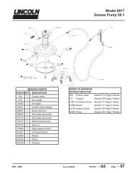
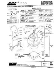
MODEL <strong>83753</strong> 3/8” AIR HOSE REELMODEL <strong>83754</strong> 1/2” AIR HOSE REELSpecifications• Spring driven, automatic rewind, with locking ratchet mechanism (eight locking positions per revolution).• Brass connectors on <strong>hose</strong> and <strong>reel</strong>Model <strong>83753</strong>• 50 Feet of 3/8” Hose• 275172 Hose ©• Incoming Air Connection: 1/4” NPT• 275174 Swivel ©• Hose Connections: Male 1/4” NPT• Maximum Pressure: 300 PSI• Maximum Air Flow: 25 CFMModel <strong>83754</strong>• 50 Feet of 1/2” Hose• 275173 Hose ©• Incoming Air Connection: 1/2” NPT• 275175 Swivel ©• Hose Connections: Male 1/2” NPT• Maximum Pressure: 300 PSI• Maximum Air Flow: 35 CFMRead and understand entire manual before assembling or using <strong>hose</strong> <strong>reel</strong>. Failure to follow instructions or warnings couldresult in personal injury and/or property damage.Safety RulesDO NOT EXCEED 300 PSI incoming <strong>air</strong> pressure (from compressor).2. Wear impact-resistant eye protection that meets ANSI Spec. Z87.1 in work area at all times.Do not release <strong>hose</strong> when rewinding. Hold <strong>hose</strong> end and allow <strong>hose</strong> to rewind slowly.Never allow children to use <strong>hose</strong> <strong>reel</strong>. Keep children clear of work area at all times.Installing Hose Reel©Note: Mounting hardware is not included and must be purchased separately. Decidefirst where <strong>reel</strong> will be mounted before purchasing hardware. Different mounting positionsrequire different types of hardware.Reel can be mounted on the floor, ceiling, or wall, wherever it is convenient. Whenchoosing a location, remember that you can only mount <strong>reel</strong> to a load-bearing structuralmember capable of supporting combined weight of <strong>reel</strong>, <strong>hose</strong>, and forces causedby pulling or maneuvering <strong>hose</strong>. Generally, mounting <strong>reel</strong> near <strong>air</strong> compressor is bestsince you can connect the two with a shorter, less expensive length of <strong>hose</strong>. Also, <strong>air</strong>compressor controls will be nearby for convenient adjusting.Once you have located a mounting spot, consult the “Typical Mounting Positions”chart below and choose the diagram that most closely matches your mounting position.If necessary, adjust guide arm position to match diagram.© Indicates changeDEC - 2006Form 402153Section - E35Page- 71B
Page Number - 2 Form 402153
ADJUSTING THE GUIDE ARMPull out 3-4 feet of <strong>hose</strong> and allow <strong>reel</strong> to lock in position.Remove the four bolts connecting guide arm to mounting base.Rotate guide arm in 90°-increments to desired position total number of positions is five (5). Replace four bolts and tighten.Continue by choosing proper mounting hardware. Mount <strong>reel</strong> using four 3/8” grade 5 bolts secured through four slots inmounting base. See Illustration for Dimensions. Use washers on mounting bolts to help bear weight of <strong>reel</strong> (Bolts and Washersare not included).After <strong>reel</strong> is secured in position, attach <strong>air</strong> <strong>hose</strong> coming from compressor. Wrap threads of male connector on incoming <strong>air</strong> <strong>hose</strong>with Teflon tape (included) or thread sealant and connect to <strong>air</strong> inlet valve on side of <strong>hose</strong> <strong>reel</strong>. Connect other end of incoming <strong>air</strong><strong>hose</strong> to <strong>air</strong> compressor. Apply Teflon tape to threads on <strong>hose</strong> before attaching <strong>air</strong> tools.ADJUSTING THE HOSE BALL STOPThe <strong>hose</strong> ball stop determines the length of <strong>hose</strong> that remains outside of <strong>reel</strong>. To adjust, pull <strong>hose</strong> out past desired position of<strong>hose</strong> ball stop and latch <strong>reel</strong>. Loosen both bolts and move ball stop to proper position. Tighten bolts.Operating Hose Reel1. Slowly pull <strong>hose</strong> from <strong>reel</strong> to desired length. A ratcheting mechanism inside <strong>reel</strong> makes a short series of clicking sounds everyhalf revolution of <strong>reel</strong>.2. To lock <strong>reel</strong> in position, listen for clicking sounds as <strong>hose</strong> is slowly pulled from <strong>reel</strong>. When <strong>reel</strong> clicks. stop pulling <strong>hose</strong>. Decreasetension on <strong>hose</strong> and <strong>reel</strong> should lock in position.3. To retract <strong>hose</strong> onto <strong>reel</strong>, slowly pull out <strong>hose</strong> until series of clicking sounds stops (1/8 revolution). DO NOT LET GO OFHOSE! Allow <strong>hose</strong> to retract slowly until <strong>hose</strong> ball stop rests against <strong>hose</strong> guide.4. Periodically check the <strong>hose</strong> for excessive wear and <strong>hose</strong> connections for <strong>air</strong> leaks.ADJUSTING RECOIL TENSION1. Disconnect incoming <strong>air</strong> supply.2. Pull out about 2 feet of <strong>hose</strong> and latch the <strong>reel</strong>.3. Remove <strong>hose</strong> ball stop.4. While firmly holding onto edge of <strong>reel</strong> drum, unlatch <strong>reel</strong> and carefully allow drum to slowly rewind, drawing <strong>hose</strong> endback through guide arm roller assembly and onto <strong>reel</strong>. Latch <strong>reel</strong> in position.5. To Increase Tension: Unlatch <strong>reel</strong> and turn clockwise (as viewed from <strong>air</strong> inlet side).To Decrease Tension: Unlatch and allow <strong>reel</strong> to rotate slowly counterclockwise (as viewed from <strong>air</strong> inlet side).6. Once desired spring tension is reached, latch <strong>reel</strong> in position. Feed <strong>hose</strong> end through roller assembly in guide arm andreattach <strong>hose</strong> ball stop.7. Connect incoming <strong>air</strong> supply.REPLACING HOSE1. Secure and stabilize <strong>reel</strong>. In most cases, <strong>hose</strong> can be replaced with <strong>reel</strong> still mounted.2. Disconnect incoming <strong>air</strong> supply.3. Pull out entire length of <strong>hose</strong> and lock <strong>reel</strong>. Make sure <strong>reel</strong> is securely locked in place.4. Unscrew <strong>hose</strong> clamps that secure <strong>hose</strong> to drum. Disconnect inlet-end of <strong>hose</strong> from <strong>air</strong> inlet valve.5. Pull inlet-end of <strong>hose</strong> through slot in drum and guide rollers. removing old <strong>hose</strong> completely.6. Remove spring <strong>hose</strong> guard, <strong>hose</strong> clamp and <strong>hose</strong> ball stop from old <strong>hose</strong>. Fit these parts on new <strong>hose</strong> in identical positions.7. Feed inlet-end of <strong>hose</strong> through guide rollers and slot in drum.8. Apply Teflon sealant tape or thread sealant to <strong>hose</strong> connector and connect to <strong>air</strong> inlet valve.9. Attach <strong>hose</strong> clamp to drum. Rewind <strong>hose</strong> onto <strong>reel</strong> using normal operation.Form 402153Page Number - 3
Lincoln Industrial Standard WarrantyLIMITED WARRANTYLincoln warrants the equipment manufactured and supplied by Lincoln to be free from defects in material and workmanship for aperiod of one (1) year following the date of purchase, excluding therefrom any special, extended, or limited warranty published byLincoln. If equipment is determined to be defective during this warranty period, it will be rep<strong>air</strong>ed or replaced, within Lincoln’s solediscretion, without charge.This warranty is conditioned upon the determination of a Lincoln authorized representative that the equipment is defective. Toobtain rep<strong>air</strong> or replacement, you must ship the equipment, transportation charges prepaid, with proof of purchase to a LincolnAuthorized Warranty and Service Center within the warranty period.This warranty is extended to the original retail purchaser only. This warranty does not apply to equipment damaged from accident,overload, abuse, misuse, negligence, faulty installation or abrasive or corrosive material, equipment that has been altered, orequipment rep<strong>air</strong>ed by anyone not authorized by Lincoln. This warranty applies only to equipment installed, operated and maintainedin strict accordance with the written specifications and recommendations provided by Lincoln or its authorized field personnel.THIS WARRANTY IS EXCLUSIVE AND IS IN LIEU OF ANY OTHER WARRANTIES, EXPRESS OR IMPLIED, INCLUDING, BUTNOT LIMITED TO, THE WARRANTY OF MERCHANTIBILITY OR WARRANTY OF FITNESS FOR A PARTICULAR PURPOSE.In no event shall Lincoln be liable for incidental or consequential damages. Lincoln’s liability for any claim for loss or damagesarising out of the sale, resale or use of any Lincoln equipment shall in no event exceed the purchase price. Some jurisdictions donot allow the exclusion or limitation of incidental or consequential damages, therefore the above limitation or exclusion may notapply to you.This warranty gives you specific legal rights. You may also have other rights that vary by jurisdiction.Customers not located in the Western Hemisphere or East Asia: Please contact Lincoln GmbH & Co. KG, Walldorf, Germany, foryour warranty rights.Lincoln Industrial Special Limited WarrantiesSPECIAL LIMITED 2 YEAR WARRANTYSL-V Series, Single Injectors-85772, 85782, and Replacement Injectors-85771, 85781Lincoln warrants the SL-V Injector series to be free from defects in material and workmanship for two (2) years following the dateof purchase. If an injector <strong>model</strong> (single or replacement) is determined to be defective by Lincoln, in its sole discretion, during thiswarranty period, it will be rep<strong>air</strong>ed or replaced, at Lincoln’s discretion, without charge.SPECIAL LIMITED 5 YEAR WARRANTYSeries 20, 25, 40 Bare Pumps, Heavy Duty and 94000 Series Bare ReelsLincoln warrants series 20, 25, 40 bare pumps, and Heavy Duty and 87000 series (94100, 94300, 94500) bare <strong>reel</strong>s to be free fromdefects in material and workmanship for five (5) years following the date of purchase. If equipment is determined by Lincoln, inits sole discretion, to be defective during the first year of the warranty period, it will be rep<strong>air</strong>ed or replaced at Lincoln’s discretion,without charge. In years two (2) and three (3), the warranty on this equipment is limited to rep<strong>air</strong> with Lincoln paying parts and laboronly. In years four (4) and five (5), the warranty on this equipment is limited to rep<strong>air</strong> with Lincoln paying for parts only.Lincoln Industrial Contact InformationTo find Lincoln Industrial’s Nearest Service Center call the following number, you may also use our websiteCustomer Service 314-679-4200Websitelincolnindustrial.comAmericas:One Lincoln WaySt. Louis, MO 63120-1578USAPhone +1.314.679.4200Fax +1.800.424.5359Europe/Africa:Heinrich-Hertz-Str 2-8D-69183 WalldorfGermanyPhone +49.6227.33.0Fax +49.6227.33.259Asia/Pacific:51 Changi Business ParkCentral 2#09-06 The SignatureSingapore 486066Phone +65.6588.0188Fax +65.6588.3438© Copyright 2006Printed in USAWeb site:www.lincolnindustrial.comPage Number - 4 Form 402153