CV11 - Total Hydraulics BV
CV11 - Total Hydraulics BV
CV11 - Total Hydraulics BV

Create successful ePaper yourself
Turn your PDF publications into a flip-book with our unique Google optimized e-Paper software.
ContentsPage 3Page 4Page 5-7Page 8-9Page 10Page 11-13Page 14Page 15General InformationTechnical dataSpool OptionsSpool ControlsPerformance CurvesAssembly DimensionsAccessoriesOrder CodeDirectional Control Valve 2Series CV 112
General InformationThe CV 112 Special Loader Valve has been designed to fit all loaders with a flow rate up to 50 l/min or 12GPM and a maximum pressure of 320 bar or 4600 psi.The CV 112 can be operated both in loaders with either open Center systems or LS systems depending onits build configuration.The CV 112 Special Loader Valve offers the loader builder a number of key features to enhance the loaderperformance such as :• Exceptional Low Spool leakage rates (less than 2 cc/min or 0.122 inch 3 /min).• Load Check valves on each spool.• Direct Acting Main Relief Valve for fast response to system over pressure.• Float Function for the lowering circuit.• Regen Function for the tilt circuit.• DIRECT MOUNTED JOYSTICK for both float and regen.• Cable Control option.• Power Beyond option.• BSP and SAE Threads are standard but also Metric and NPTF can be offered upon request.Directional Control Valve 3Series CV 112
Technical DataMax pressure settingMain relief valveTank LineFlow ratesMax flow A/BTemperature rangeStandard sealsSpool leakage at100 bar (1450 psi) and 46 mm²/s (cSt)Viscosity A and B portbar32010l/min50° C-40 to +80cm³/min2psi4600145US gpm13°F-40 to +176inch³/min0.12FiltrationContamination level equal to or better thenViscosityRecommended operatingViscosity rangeWeightCV 112Operating forcerequired for spool movementSpring centeredDetent inDetent outNumber of work sections19/16 according to ISO 4406mm²/s10-400kg4,9N1302302002NAS 1638-class 10cSt47 - 1875lbs10,8kp2952452Directional Control Valve 4Series CV 112
Spool OptionsSTANDARD THREADSInletPort Sizes BSP UNF MetricP1 G ⅜ ¾-16 (SAE 8) M18x1.5P2 G ⅜ ¾-16 (SAE 8) M18x1.5P3 G ⅜ ¾-16 (SAE 8) M18x1.5Cylinder PortsA-B G ⅜ 9 /16-18 (SAE 6) M16x1.5TankT1 G ½ ⅞-14 (SAE 10) M22x1.5T2 G ⅜ ¾-16 (SAE 8) M18x1.5T3 G ⅜ ¾-16 (SAE 8) M18x1.5SPOOL FOR OPEN CENTERED VALVESPart No. Spool type Type Symbol SP-No.Single Acting A port10573-3B 2SA SP-10573-3Bwith metering10574-3B 2XA Single Acting A port SP-10574-3B10309-3B 3X DA + Float SP-10309-3BDA + Float10308-3B 3Swith meteringSP-10308-3BDA + Float10307-3B 3Rwith meteringSP-10307-3BA BP TA BP TA BP TA BP TA BP TA B10575-3B 4X Motor spool SP-10575-3BP TA BMotor spool10576-3B 4Swith meteringSP-10576-3BP TDA + Regen10310-3B 8Rwith meteringSP-10310-3BDA + Regen10311-3B 8Swith meteringSP-10311-3BA BP TA BP TDirectional Control Valve 5Series CV 112
Spool OptionsSPOOLS FOR LOAD SENSING OPTIONPart No. Spool type Type Symbol SP-No.Single Acting10577-3B 2RALS SP-10577-3Bwith meteringSingle Acting10578-3B 2SALS SP-10578-3Bwith meteringA BP TA BP TA BDA + Float10548-3B 3RLS with meteringSP-10548-3BDA + Float10549-3B 3SLSwith meteringSP-10549-3BDA + Float10551-3B 8SLSwith meteringSP-10551-3BDA + Float10550-3B 8RLSwith meteringSP-10550-3BP TA BP TA BP TA BP TClosed CenterOpen CenterDirectional Control Valve 6Series CV 112
Spool OptionsCodeType A-sideB-side TypeCode9Spring centered.30.1[1.19]M8x125M8x1.2510Detent in pos.1,2and 353[2.09]64[2.52]Hand lever.EncasedS51112Spring centered.Detent in pos.4(FLOAT)Spring centered.Detent in pos.3 and 450.8[2.00]52[2.05]Mechanical joystickdor dual-spoolcontrol.33[1.30]S614Spring centered.Detent in pos.382[3.23]13Spring centered.Detent in pos.245.8[1.80]Wire control18Spring centered.Pressure point inpos.5 (REGEN)W98[3.86]5Spring centered.Detent in position2 and 459[2.32]For different Joystick and mounting configurationsincluding Float and Regen functions please see page 8,9and 10.PPPPneumatic on/offPneumaticproportionalCylinder ports facing upEPElectropneumaticon/off.12V/270mA alt.24V/150mA.Hirschmann connectoris standard.Other connectors areavailable on request.Cylinder ports facing downDirectional Control Valve 7Series CV 112
Spool ControlsJoystick Specification - Honrizontal mountingPORTS UPPORTS DOWNIIIIIIIVIIIIIIIV1. Check port/hose orientationPorts upPorts down2. Fill in functions (handwrite)LiftLowerFloatCurl inCurl outRegenPlease fill in corresponding Roman numerals3. Valve Mounting HolesThrough casting holesThreaded bottom holesDirectional Control Valve 8Series CV 112
Spool ControlsJoystick Specification - Vertical mountingPORTS LEFTPORTS RIGHTIIIIIIVIIIIVIIII1. Check port/hose orientationPorts leftPorts right2. Fill in functions (handwrite)LiftLowerFloatCurl inCurl outRegenPlease fill in corresponding Roman numerals3. Valve Mounting HolesThrough casting holesThreaded bottom holesDirectional Control Valve 9Series CV 112
Performance CurvesDirectional Control Valve 10Series CV 112
AssemblyCV 110DimensionsAssembly DimensionsCV 110 Assembly DimensionsValve with Encased Hand LeverValve withEncased Hand Leveralve withncased Hand Lever- 11 -Directional Control Valve 11Series CV 112
Assembly CV 110 DimensionsAssembly DimensionsValve with Mechanical JoystickValve with MechanicalJoystick- 12 -Directional Control Valve 12Series CV 112
Assembly DimensionsCV 110 Assembly DimensionsValve with Electrical Hydraulic Proportional Spool ControlValve with ElectricalHydraulic ProportionalSpool Control- 13 -Directional Control Valve 13Series CV 112
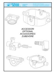
essoriesh pressure carry-over adapter, shouldpressure carry-over adapter, shouldnstalled in in the T1-port when two two or or more moreves h pressure Accessoriess areareusedused carry-overinin the same adapter, circuit. shouldcircuit.T2T2mustmustn nstalled be connected in the T1-port to Tank when two or morebe connected to Tankes are used in the same circuit. T2 mustbe connected to TankHigh pressure carry-over adapter, should beinstalled in the T1-port when two or morevalves are used in the same circuit. T2 mustType BSPType BSPPart No.10534-4SType Part then be No.10534-4S BSP connected to TankPart No.10534-4SPart No.10534-4STank Tank port port reduction reduction adapter, adapter, can be can beinstalled installed the in T1-port the T1-port when the when thread the size thread isto betoreduced.be reduced.Tank port reduction adapter, can beinstalled in the T1-port when the thread size isto be reduced.Tank port reduction adapter, can be installedin the T1-port when the thread size is to bereduced.Type BSP ½ to BSP Type BSP Part ½ No.10348-4S to BSP Part No.10348-4SType BSP ½″ to BSP ⅜″Part No.10348-4SType BSP ½ to BSP Part No.10348-4SType UNF UNF SAE # SAE 10 to # SAE 10 to # 8SAE # 8Part Part No.10536-4SSAE Part # 10 No.10349-4Sto SAE # 8Part No.10349-4SPart No.10536-4SPart No.10349-4SType UNF SAE # 10 to SAE # 8Part No.10536-4SPart No.10349-4Sererdard Lever :Leverdard Lever :rard Lever :Standard Lever :Part No. 10347-4SPart No. 10347-4SPart No. 10347-4SOther length on request.er length on request.er length on request.- 14 -Directional Control Valve 14Series CV 112Part No. 10347-4S