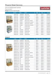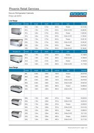
Waitrose Specification - Phoenix Retail Services
Waitrose Specification - Phoenix Retail Services
Waitrose Specification - Phoenix Retail Services

You also want an ePaper? Increase the reach of your titles
YUMPU automatically turns print PDFs into web optimized ePapers that Google loves.
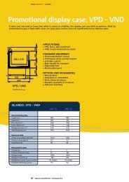
INSTALLATION INSTRUCTIONSLOCATIONThis refrigerated display case has been designed for displaying and the storage of perishable foodproduct. It is engineered for air-conditioned stores with a maximum ambient of 24°C and 50%relative humidity.When selecting the location for placement of this case, avoid the following conditions:1. Excessive air movementA. DoorsB. Air-conditioned ventsC. Other air sources2. Excessive heatA. WindowsB. SunC. Flood lamps 8 feet or less from the productD. Other heat sources.CRATE REMOVALMove case as close as possible to its location. Remove all crating and shipping braces above theshipping pallet. Loosen the plastic dust cover from the pallet, but leave cover over the case toprotect it while removing the case from the pallet.This case may be fitted with 4 or more leveling pads or casters. Carefully lift the case up and offthe pallet so leveling pads clear the pallet. When the case is in location, remove the dust cover.NOTE - Self-Contained cases may be equipped with a shipping block under the compressor.This block must be removed upon installation. Failure to remove the block will result inexcessive noise, refrigerant leaks and will void warranty protection. Loosen all four nuts onthe compressor hold down screws. Lift or pry the compressor up and remove the shipping block.Do not retighten screws as the compressor should be left free to float on the spring mounts.For proper refrigeration performance, PRODUCT MUST NOT BE PLACED IN APOSITION WHERE IT MAY AFFECT THE AIR CURTAIN.6
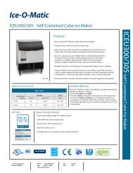
REFRIGERATION INFORMATIONREFRIGERATION SYSTEMINTEGRAL UNITCompressor:DWM Copeland KARB-010E-CAVRefrigerant:R-404AExpansion Device:Sporland Q-Series w/ #2 OrificeEvaporator:Heatcraft 4x12x39 3R 8DEvaporator Motor: 9 watt Shaded pole [2]Thermostat:Ranco ETC-111000 or Johnson Control MR1DR230-11CTimer:Graslin FM/1StuFan delayTI 3NT01L-3635LDefrost Terminator:TI 3NT01L-3635LDefrost Heater Temco 300 Watt [2]Condenser:Heat craft 12x14x6 6R 3FPICondenser Motor50 Watt Shaded PoleREFRIGERATION OPERATIONThe refrigeration cycle is thermostatically controlled by a single stage electronic Thermostat. When thethermostat cut out point is reached, the circuit to the liquid line solenoid is opened de-energizing thesolenoid, causing the compressor to pump down. When the compressor pumps down to 20-25 psi the lowpressureswitch opens and power is terminated to the compressor.Defrost TypeDefrost scheduleDefrost terminationFan terminationElectric6 defrost periods per day for 15 min.12.8*C.12.8*C.Typical component SettingsController cut-outDifferentialTXVPressure switch-6.0*C.3K4*C. superheatPL cut out 25psi cut in 60psiHP 350psi7
ELECTRICAL DATA220v – 20 amp single phaseNOTE: An all pole disconnect, with a separation of at least 3mm in all poles must be incorporated in thefixed wiring.NOTE: I/O cable needs to be in metal conduit.Normal Operating ParametersAir on coil:Air off coilSuction pressureCondensing pressureAir on condenserAir off condenserEvaporator temperatureSuction temperature4*C.-4*C.53psi230psi20*C.28*C.-8*C.-4*C.8
ELECTRICAL SCHEMATICSDI-606 with TSTAT10
ELECTRICAL SCHEMATICSDI-606 with RTC11
Lighting SystemTo Replace Light Bulb:1. Switch off the electricity supply at the main source.2. Remove the tube by rotating it through 90°, so that the pins at both ends arealigned vertically. Carefully lift it away from the fitting.3. Undo the retainer screw in the side of the fitting and carefully ease off thecover.4. Replace bulb.5. Lights will not work if the bulb is not fully seated.6. Re attach the cover to the fitting.12
To access timer and control, remove lower panel by removing the two top screws on eachsection.Grasslin TimerThermostatControlPressure SwitchTo access pressure switchremove top two screws oflower panel.16
MAINTENANCE INFORMATIONCLEANINGNOTE: TURN POWER OFF BEFORE CLEANING CASE.Case ExteriorClean surfaces frequently with warm water and mild detergent.Do not use strong alkali solutions, steel wool, or abrasive cleansers.Evaporator CoilClean as needed.Condenser CoilClean condenser coil every three months or as needed with a whiskbroom or vacuum.DISCONNECT POWER WHEN SERVICING. FINS ON CONDENSER COILARE SHARP!BOTTOM SHELF REMOVALTo remove bottom deck raise front and lift out towards you.LOAD LIMITSDO NOT place product in merchandisers until all refrigeration controls have been adjusted andare at the proper operating temperature.DO NOT over load shelving or place product where it may affect the air curtain.17
SERVICEDISCONNECT THE ELECTRICAL POWER WHEN SERVICINGOR REPLACING ANY ELECTRICAL COMPONENT.Contact Service Department at 011-319-293-3777 or service@barkercompany.comSee labels under plate shelf to locate components in each panel.To remove panels, remove top screws and pull panel out and away from case.18
EVAPORATOR ACCESS1. Remove product pans2. Tilt product pan holder up at narrow end..3. Move product holder forward, liftrear of holder up and remove.4. Move crumb tray back, tilt diagonal, lift up and out.19
Evaporator Fans1. Evaporator fans are located underneath the bottom deck.3. Remove cover plate to access fan motor.4. To remove plate, remove the 4 screws shown.Evaporator Coil AccessTo gain access to Evaporator Coil:1. Remove bottom deck bylifting the front of each sectionand pulling out.2. Remove the screws on theaccess plate and remove plate.20