SCU 515/535 - Phoenix Retail Services
SCU 515/535 - Phoenix Retail Services
SCU 515/535 - Phoenix Retail Services
- No tags were found...

Create successful ePaper yourself
Turn your PDF publications into a flip-book with our unique Google optimized e-Paper software.
<strong>SCU</strong> <strong>515</strong>/<strong>535</strong> CONTROL PANELService manualSelecting a certain menu (see appropriate menu for the access combination).1. Running through menu: or2. Closing menu:4.2 Changing settingsThe set values can be changed according to customer requirements. When the setting to bechanged is shown on the display, this can be changed by pressing the "SET" key and the "UP"or "DOWN" key at the same time until the required value appears. Another setting can then bechanged or you can return to the previous menu by pressing "PRG".Changing settings: + orClosing menu:5 SETTINGS MENU5.1 Selecting settings menuThis menu is the only menu that is also accessible to the user; it can be activated with the "PRG"key. The set point of section 1 is immediately visible. You can then go through the whole menuby pressing the "UP" or "DOWN" key. The functions you see here are dealt with in section 5.2.Activating settings menu:SMEVA PRODUCTS 9
<strong>SCU</strong> <strong>515</strong>/<strong>535</strong> CONTROL PANELService manual5.2 Functions within the settings menuSet point section 1,2,3Here you can set the set points of cooling section 1 and, if present, the set points of sections 2 and3 can be set within the temperature range -40 °C...20 °C (depending on the type of coolingfurniture). If a "+" symbol flashes to the right of the set point, this means that the night offset hasswitched on.ID. 1: The Masterliner static and the SM 3000 are set at evaporator-temperature. The Vision,the Masterliner dynamic, the Showliner dynamic and static, the SM 5000 and the coolingand freezing cells are set at air temperature. The evaporator temperature is measured bya sensor located in the evaporator. The air temperature is measured by two sensors, oneon the air intake side and one on the air expel side of the evaporator and the average ofthe two temperature measurements is taken.ID. 2: The switching off temperature of section 2 and 3 should not be colder than the switchingoff temperature of section 1 if the cooling device is connected to a stand alone machine.Capacity humidifierHere you can set the capacity of the air humidifier (10%, 20%…and 100%).ID. This function is only available on Smeva showcases in which an air humidifier of the typeultrasonic compact has been installed.TimeHere you can set the time.ID. Mind the summer-/winter-time, set time by hand.DateHere you can set the date.ID. Mind a leap-year, set date by hand.6 TYPE MENU6.1 Select type menuIn the type menu you can select a Smeva product, after which all standard set values of theselected product are programmed fully automatically (see appendix 2). The type menu can beselected by pressing the "PRG" key and the lighting key at the same time. After 5 seconds theset type of cooling unit appears on the display. You can then go through the menu by pressingthe "UP" or "DOWN" key. The functions you see here are dealt with in section 6.2.Select type menu: +SMEVA PRODUCTS 10
<strong>SCU</strong> <strong>515</strong>/<strong>535</strong> CONTROL PANELService manual6.2 Functions within the type menuModel typeWith this function you can set the model which is to be regulated by this control. When thissetting is used, the corresponding default values are set automatically (see appendix 2).Temperature readoutWith this function you can select a temperature in degrees Celsius or degrees Fahrenheit.Number sectionsYou can set the number of cooling sections with this function. (Only applies to the <strong>SCU</strong> <strong>535</strong>)ID.: If for testing purposes the type menu is selected and a different type is set, the setsecond and third sections disappear. They will then have to be programmed afresh(see section 6.2 for further details).7 FUNCTION MENU7.1 Selecting function menuThe function menu can be selected by pressing the "PRG" and "DOWN" keys at the same time."FUNCTIONS MENU" appears on the display after 5 seconds. The menu will be activated bypressing the "SET" key. The actual temperature in the evaporator of section 1 appears in thedisplay. You can then go through the menu by pressing the "UP" or "DOWN" key. Thefunctions you see here are dealt with in section 7.2.Select function menu: +SMEVA PRODUCTS 11
<strong>SCU</strong> <strong>515</strong>/<strong>535</strong> CONTROL PANELService manualActivate function menu:7.2 Functions within the function menuEvaporator temperature 1, 2, 3 (functions 1-3)These functions display the actual evaporator temperatures of the cooling sections.RH sensor (function 5)This function indicates if there is an air humidity sensor connected (yes) or not (no). If a sensoris connected, the air humidity content is displayed on the bottom right of the display. A black dotto the left of this value indicates that humidification is taking place at that moment.Night offset at light off (function 6)With this function you can set the night offset to come on when the light is switched off (yes) ornot (no).Moist at cooling (function 7)This function indicates whether humidification is automatically switched on (yes) or not (no)when the cooling is on.Moist at section 1 (function 8)With this function you can set whether the humidification is automatically switched on (yes) ornot (no) by the temperature switch in section 1.Moist at defrost (function 9)With this function you can set whether the humidification in on (yes) or not (no) duringdefrosting.Window heat at cooling (function 10)With this function you can set whether the window heating is automatically switched on (yes)or not (no) when the cooling is on.Window heat at night offset (function 11)With this function you can set whether the window heating remains switched on (yes) or not (no)when the night offset is on.Extra function or alarm (function 12)Here you can select an additional function, such as an additional display shelf or bottom coolingor an alarm function. If this function is taken an alarm function can be generated via the RS 485port and interface. For further details about this, see enclosure 1A.Extra function at light off (function 13)SMEVA PRODUCTS 12
<strong>SCU</strong> <strong>515</strong>/<strong>535</strong> CONTROL PANELService manualWith this function you can set whether the additional function remains switched on (yes) or not(no) when the light is switched off.Extra function at cooling (function 14)With this function you can set whether the additional function is automatically on (yes) or not(no) when the cooling is switched on.Extra function at defrost (function 15)With this function you can set whether the additional function is on (yes) or not (no) duringdefrosting.Fans at section 1 (function 85, walk-in freezer M30 only)With this function, it is possible to set whether the fans do (yes) or do not (no) stay on duringdefrost.Extra function at section 1 (function 16)With this function you can set whether the additional function is automatically switched on (yes)or not (no) by the temperature switch in section 1.Hysteresis 1,2,3 (functions 17-19)With this function you can set the differential (the difference between switching on and switchingoff temperature) for each section. This can be set between 1 and 10 K.Night offset (function 20)With this function the night offset can be set between 0 and 5 K and there is always a raising oftemperature with regard to the day setting.For example: With a set point of - 4 °C and an offset of 2 K, the night switching off temperatureis raised to - 2 °C.Data-log alarm (function 21)This alarm function indicates by means of an alarm when the memory is full. This alarm isshown on the interface by LEDs. The memory can be emptied using a PC with the correctSmeva <strong>SCU</strong> software. No complications arise when the memory is full: the oldest informationis then overwritten with new data.Function test (function 22)The function test is an inspection of the functioning of the control it self. If 'function test' isset to "yes", the control itself controls the operation of the LEDs. Then the control asks topress once on every key, this to inspect the connection of the keys and the print. The relay isthen tested. The different relays can be energised by repeatedly pressing “UP”. Finally thecontrol inspects the relays and the analog outputs. Between every inspection one has to pressthe "PRG" key.SMEVA PRODUCTS 13
<strong>SCU</strong> <strong>515</strong>/<strong>535</strong> CONTROL PANELService manualLast error (functions 23-28)These 6 functions (23-28) show in the form of a code the last 6 errors identified by the control.This code is given numerically with date and time. The next 4 errors can be shown:E 1,2,3,4,5,6,7,8,9 = An error has been identified in one of the maximum 9 sensors. Seeparagraph 9.2 for an explanation of the various sensors. There could be akink in the cable of the sensor or the connector could have been detached.HI 1,2,3 = The temperature in the section in question is too high according tothe settings of the alarmmenu. Maybe the upper temperature limitis adjusted too low.LO 1,2,3 = The temperature in the section in question is too low according to thesettings of the alarmmenu. Maybe the lower temperature limits is adjustedtoo high.EE = An error has been identified in the settings. The control has to be replaced.Example: 16:00 22-05 E2: At 16:00 hours on may 22, an error is identified in sensor 2Serial number (function 29)This indicates the serial number of the control panel.Software version (function 30)This indicates the software version.IP change 1,2,3 (function 31-33)This stores the data of the last 3 changes in the user and service menu.Start cool 1,2,3 (functions 34, 36, 38)This function indicates the number of times switched on/off in the last 24 hours. This functioncan be used as an aid when tracing a fault in a showcase.Time cool 1,2,3 (functions 35, 37, 39)This function indicates the total cooling time over the last 24 hours per section; it indicates theoperating time percentage and is therefore an aid when tracing a fault in the cooling device.Network number (function 90)With this function, the network number can be set that corresponds to the control unit inquestion. In larger stores, several control units can be called up remotely via a P.C. Each unitthus has its own network number for calling up the correct unit.Log interval (function 91)With this function, it is possible to set the number of minutes’ interval at which the controlunit stores the log.SMEVA PRODUCTS 14
<strong>SCU</strong> <strong>515</strong>/<strong>535</strong> CONTROL PANELService manual8 DEFROST MENU8.1 Selecting defrost menuThe defrost menu can be selected as follows. If the "PRG" and "DOWN" keys are pressed atthe same time, after 5 seconds 'FUNCTIONS MENU' appears on the display. By pressing the"UP" key once, 'DEFROST MENU' appears in the display. This menu can be activated bypressing the "SET" key. The first start time for the defrosting is now shown on the display. Youcan now go through the menu by pressing the "UP" or "DOWN" key. The functions you seehere are dealt with in section 8.2.Select defrost menu: + followed byActivate defrost menu:8.2 Functions within the defrost menuSMEVA PRODUCTS 15
<strong>SCU</strong> <strong>515</strong>/<strong>535</strong> CONTROL PANELService manualStart defrost 1,2,3,4,5,6 (functions 40, 42, 44, 46, 48, 50)With these functions you can set the 6 start times of the automatic defrosts. Manual defrostingis also possible, see section 11. If you want less than 6 defrosts per 24 hours, you can "switch off"a start time by pressing "SET" and "DOWN" at the same time until "OFF" appears on the display(this mode appears between 23.59 and 00.00 on the display).Maximal defrost time 1,2,3,4,5,6 (functions 41, 43, 45, 47, 49, 51)With this function you can enter the maximum defrost times (up to a maximum of 3 hours). Thedefrosting ends when this maximum defrost time is completed or if the defrost end temperatureis reached.Fan delay after defrost (function 52, only freezing cell M30!)With this function you can set the fan delay after defrosting to a maximum of 1 hour.Electric defrost (function 53, only freezing cell M30!)With this function you can select between defrosting the freezing cell electrically or in a naturalmanner. In the case of electric defrosting, the humidification relay is used, as there is nohumidification in a freezing cell.Fans at defrost (function 86, walk-in freezer M30 only!)With this function, it is possible to set whether the fans do (yes) or do not (no) stay on duringdefrost.Display fixed at defrost (function 54)With this you can select whether the read out section temperatures are "maintained" on thedisplay during defrosting (yes) or whether the read out actual section temperatures (no) are shownincrease on the display.End of defrost section 1,2,3 (functions 55-57)With this function the defrost end temperatures can be set for the 3 cooling sections. Thedefrosting ends when this temperature is reached or when the maximum defrost time iscompleted. LED 19 will be lit during defrosting and will flash for 10 minutes after defrosting.SMEVA PRODUCTS 16
<strong>SCU</strong> <strong>515</strong>/<strong>535</strong> CONTROL PANELService manual9 CALIBRATION MENU9.1 Selecting calibration menuThe calibration menu can be selected as follows. If the "PRG" and "DOWN" keys are pressedat the same time, after 5 seconds 'FUNCTIONS MENU' will appear on the display. By pressingthe "UP" key twice, 'CALIBRATION MENU' appears on the display. This menu can beactivated by pressing the "SET" key. Adjustment sensor 1 appears on the display. You can thengo through the menu by pressing the "UP" or "DOWN" key. The functions you see here aredealt with in section 9.2.Select calibration menu: + followed by 2xActivate calibration menu:9.2 Functions within the calibration menuAdjustments sensor 1,2,3,4,5,6,7,8,9 (functions 58-66)With these functions you can calibrate the readout of the sensors. Each sensor has acalibration indication (at the connections). If this is greater than 0.3 K, it should be calibrated.SMEVA PRODUCTS 17
<strong>SCU</strong> <strong>515</strong>/<strong>535</strong> CONTROL PANELService manualIf the temperature readout of the sensor in question is then still not correct, a 1% accurateresistor of 815 Ω should be connected at the sensor input and the common input. The displayshould then read 0 degrees Celsius. For a rear view of the control unit see enclosure 1A andfor how to calibrate the sensors see enclosure 1E.sensor 1 in display = input S11 of control (intake temp. for the evaporator coil in section 1)sensor 2 in display = input S12 of control (outlet temp. under the evaporator coil in section 1)sensor 3 in display = input S13 of control (defrost end temp. or current evaporator temp. insection 1)sensor 4 in display = input S21 of control (intake temp. for the evaporator coil in section 2)sensor 5 in display = input S22 of control (outlet temp. under the evaporator coil in section 2)sensor 6 in display = input S23 of control (defrost end temp. or current evaporator temp. insection 2)sensor 7 in display = input S31 of control (intake temp. for the evaporator coil in section 3)sensor 8 in display = input S32 of control (outlet temp. under the evaporator coil in section 3)sensor 9 in display = input S33 of control (defrost end temp. or current evaporator temp. insection 3)Display offset section 1,2,3 (functions 67-69)With these functions the display value for the three cooling sections can be changed severaldegrees (-10, 9.9 .... +10 K).SMEVA PRODUCTS 18
<strong>SCU</strong> <strong>515</strong>/<strong>535</strong> CONTROL PANELService manual10 ALARM MENU10.1 Select alarm menuThe alarm menu can be selected as follows. If the "PRG" and "DOWN" keys are pressed at thesame time, after 5 seconds 'FUNCTIONS MENU' appears on the display. By pressing the "UP"key 3 times, 'ALARM MENU' will appear on the display. To activate this menu it must beselected with the "SET" key. 'Delay alarm 1' now appears on the display. You can now gothrough the menu by pressing the "UP" or "DOWN" key. The functions you see here are dealtwith in section 10.2.worden in paragraaf 10.2 behandeld.Select alarm menu: + followed by 3xActivate alarm menu:10.2 Functions within the alarm menuDelay alarm 1,2,3 (functions 70-72)With these functions the reaction delays of the alarm in sections 1, 2 and 3 can be set up to amaximum of 4 hours.HI alarm 1,2,3 (functions 73-75)With these functions the alarm for too high temperatures in cooling sections 1, 2 and 3 can beswitched on and off.SMEVA PRODUCTS 19
<strong>SCU</strong> <strong>515</strong>/<strong>535</strong> CONTROL PANELService manualHI temperature 1,2,3 (functions 76-78)With these functions the upper limit temperatures of the alarm for the cooling sections can be set,provided they are at least 5 degrees Celsius higher than the lower limit temperatures.ID. This means air temperature.LO alarm 1,2,3 (functions 79-81)With these functions the alarm for too low temperatures in cooling sections 1,2 and 3 can beswitched on and off.LO temperature 1,2,3 (functions 82-84)With these functions the lower limit temperatures of the alarm for the cooling sections can be set,provided they are at least 5 degrees Celsius lower than the upper limit temperatures.ID. This means air temperature.11 OTHER FUNCTIONS11.1 Manual defrostingManual defrosting is also possible in addition to the defrosts set in the menu. This can be startedby pressing the "SET" and "DOWN" key at the same time:Select manual defrosting: +The defrost lamp (LED 18) then lights up. Manual defrosting ends when the defrost endtemperature is reached or when the maximum defrosting time of 3 hours is completed.11.2 Additional connectionsThree additional displays can be connected to the control panel, for the temperature readout onthe customer side (for the <strong>SCU</strong> <strong>535</strong>). An emergency power supply in the form of a battery canalso be connected to the control panel so that the data for the log functions are stored in thecircular memory if there is a power cut. In this case "power drop" appears on the display. Bypressing the "SET" key, this message is deleted from the display:The battery is also automatically recharged by the control when the voltage (mains power) isrestored.SMEVA PRODUCTS 20
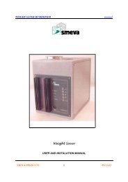
<strong>SCU</strong> <strong>515</strong>/<strong>535</strong> CONTROL PANELService manual12 ENCLOSURESEnclosure 1A: Back view of controlConnections:Sensors : 9 x KTY81-1 Sensors: RH Sensor 0-1 Vdc signal, 12 VdcRelais : Moist (NO, 250 Vac / 5A inductif, 8A not inductif): Light (NO, 250 Vac / 5A inductif, 8A not inductif): Window heating (NO, 250 Vac / 5A inductif, 8A not inductif): Fan (NO, 250 Vac / 5A inductif, 8A not inductif): Extra function (NO, 250 Vac / 5A inductif, 8A not inductif): Cooling section 1 (NO, 250 Vac / 5A inductif, 8A not inductif): Cooling section 2 (NO, 250 Vac / 5A inductif, 8A not inductif): Cooling section 3 (NO, 250 Vac / 5A inductif, 8A not inductif)Analoge Ausgang: 0-10 Vdc Moist capacity (0 - 100%)Kommunication : RS485: 3 remote display unitsEnclosure 1B: Replacing the fuseSMEVA PRODUCTS 21
<strong>SCU</strong> <strong>515</strong>/<strong>535</strong> CONTROL PANELService manualWhen the functions of the control are out of order, although the 220 Volt is adapted, mostprobably the fuse is burnt out. The fuse can be replaced by removing the rear coverplate of thecontrol box. The fuse is 250 V, 315 mA laxly.Enclosure 1C: Jumper for the end of a networkWhen the control unit is connected to the end of a communication network, a jumper must beplaced at the rear of the control unit. Where a control unit is not connected to the end of acommunication network, this jumper must be removed.Enclosure 1D: Technical specificationsPower supply: 230 Vac / 50 - 60 Hz. (-10% / +5%) or 115 Vac/ 50 - 60 Hz.(-10% / 5%)Emergency power supply : 12 V DC (option)Range : -40 / +30 °C per 1°C: 10 / 100 % RHFunction temperature : -20 / +40 °CStorage temperature : -20 / +60 °CFunctioning area RH : 10 - 90% RH not condensingAccuracy : +/- 0.5 % of the rangeHouse: Aluminium profileDimensions : 300 x 72 x 71 mm (b x h x d)Front: PolycarbonateSecurity:This control is in accordance with the CE- marking.Enclosure 1E: Calibrating the sensorsThe sensors can be calibrated by putting them in a glass of water with melting ice in it. Thetemperature of the water is 0 °C. The resistance of the sensor must be 817 Ω then, as can beseen in the table below.T amb. Resistance-55 495-50 514-40 568-30 625-20 686-10 7500 81710 88720 96125 100030 103940 112050 120560 1295Resistance105010401030102010101000990980970960950940930920910900890880870860850840830820810800790780770760750740730KTY81 sensorSMEVA PRODUCTS72022710700690680670660650-15 -14 -13 -12 -11 -10 -9 -8 -7 -6 -5 -4 -3 -2 -1 0 1 2 3 4 5 6 7 8 9 10 11 12 13 14 15 16 17 18 19 20 21 22 23 24 25T amb.
<strong>SCU</strong> <strong>515</strong>/<strong>535</strong> CONTROL PANELService manual70 139080 148990 1591100 1696110 1804120 1915130 2017140 2120150 2225Enclosure 2: Default values <strong>SCU</strong> <strong>515</strong>/<strong>535</strong>The default values for each type of cooling unit are given in the following pages as preprogrammedas standard.SMEVA PRODUCTS 23