The use of anti-vibrating bearings in the Taiwan High ... - Alga S.p.A.
The use of anti-vibrating bearings in the Taiwan High ... - Alga S.p.A.
The use of anti-vibrating bearings in the Taiwan High ... - Alga S.p.A.

You also want an ePaper? Increase the reach of your titles
YUMPU automatically turns print PDFs into web optimized ePapers that Google loves.
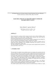
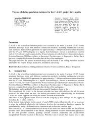
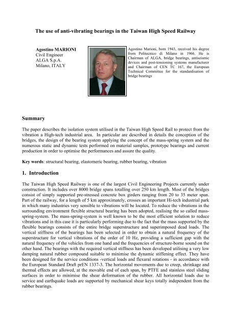
<strong>The</strong> <strong>use</strong> <strong>of</strong> <strong>anti</strong>-<strong>vibrat<strong>in</strong>g</strong> <strong>bear<strong>in</strong>gs</strong> <strong>in</strong> <strong>the</strong> <strong>Taiwan</strong> <strong>High</strong> Speed RailwayAgost<strong>in</strong>o MARIONICivil Eng<strong>in</strong>eerALGA S.p.A.Milano, ITALYAgost<strong>in</strong>o Marioni, born 1943, received his degreefrom Politecnico di Milano <strong>in</strong> 1966. He isChairman <strong>of</strong> ALGA, bridge <strong>bear<strong>in</strong>gs</strong>, <strong>anti</strong>seismicdevices and post-tension<strong>in</strong>g systems manufacturerand Chairman <strong>of</strong> CEN TC 167, <strong>the</strong> EuropeanTechnical Committee for <strong>the</strong> standardisation <strong>of</strong>bridge <strong>bear<strong>in</strong>gs</strong>Summary<strong>The</strong> paper describes <strong>the</strong> isolation system utilised <strong>in</strong> <strong>the</strong> <strong>Taiwan</strong> <strong>High</strong> Speed Rail to protect from <strong>the</strong>vibration a <strong>High</strong>-tech <strong>in</strong>dustrial area. In particular are described <strong>in</strong> details <strong>the</strong> conception <strong>of</strong> <strong>the</strong>bridges, <strong>the</strong> design <strong>of</strong> <strong>the</strong> bear<strong>in</strong>g system apply<strong>in</strong>g <strong>the</strong> concept <strong>of</strong> <strong>the</strong> mass-spr<strong>in</strong>g system and <strong>the</strong>numerous static and dynamic tests performed on material samples, prototype <strong>bear<strong>in</strong>gs</strong> and currentproduction <strong>in</strong> order to optimise <strong>the</strong> performances and assure <strong>the</strong> quality.Key words: structural bear<strong>in</strong>g, elastomeric bear<strong>in</strong>g, rubber bear<strong>in</strong>g, vibration1. Introduction<strong>The</strong> <strong>Taiwan</strong> <strong>High</strong> Speed Railway is one <strong>of</strong> <strong>the</strong> largest Civil Eng<strong>in</strong>eer<strong>in</strong>g Projects currently underconstruction. It <strong>in</strong>cludes over 8000 bridge spans totall<strong>in</strong>g over 250 km length. Most <strong>of</strong> <strong>the</strong> bridgesconsist <strong>of</strong> simply supported pre-stressed concrete box girders rang<strong>in</strong>g from 20 to 35 meter span.Part <strong>of</strong> <strong>the</strong> railway, for a length <strong>of</strong> 5 km approximately, crosses an important Hi-tech <strong>in</strong>dustrial park<strong>in</strong> which many <strong>in</strong>dustries very sensible to vibrations will be located. To reduce <strong>the</strong> vibrations <strong>in</strong> <strong>the</strong>surround<strong>in</strong>g environment flexible structural bear<strong>in</strong>g has been adopted, realis<strong>in</strong>g <strong>the</strong> so called massspr<strong>in</strong>g-system.<strong>The</strong> mass-spr<strong>in</strong>g-system is well known to be <strong>the</strong> most efficient solution to reducevibrations and <strong>in</strong> this case it is particularly perform<strong>in</strong>g due to <strong>the</strong> fact that <strong>the</strong> mass supported by <strong>the</strong>flexible <strong>bear<strong>in</strong>gs</strong> consists <strong>of</strong> <strong>the</strong> entire bridge superstructure and superimposed dead loads. <strong>The</strong>vertical stiffness <strong>of</strong> <strong>the</strong> <strong>bear<strong>in</strong>gs</strong> has been selected <strong>in</strong> order to obta<strong>in</strong> a natural frequency <strong>of</strong> <strong>the</strong>superstructure for vertical vibrations <strong>of</strong> <strong>the</strong> order <strong>of</strong> 10 Hz, provid<strong>in</strong>g a sufficient gap with <strong>the</strong>natural frequency <strong>of</strong> <strong>the</strong> vehicles from one hand and <strong>the</strong> frequencies <strong>of</strong> structure-borne sound on <strong>the</strong>o<strong>the</strong>r hand. <strong>The</strong> <strong>bear<strong>in</strong>gs</strong> with <strong>the</strong> required vertical stiffness has been developed utilis<strong>in</strong>g a very lowdamp<strong>in</strong>g natural rubber compound suitable to m<strong>in</strong>imise <strong>the</strong> dynamic stiffen<strong>in</strong>g effect. <strong>The</strong>y havebeen designed for <strong>the</strong> service conditions -vertical loads and flexural rotations - <strong>in</strong> accordance with<strong>the</strong> European Standard Draft prEN 1337-3. <strong>The</strong> horizontal movements due to creep, shr<strong>in</strong>kage and<strong>the</strong>rmal effects are allowed, at <strong>the</strong> movable end <strong>of</strong> each span, by PTFE and sta<strong>in</strong>less steel slid<strong>in</strong>gsurfaces <strong>in</strong> order to m<strong>in</strong>imise <strong>the</strong> shear deformation <strong>of</strong> <strong>the</strong> rubber. All horizontal loads due toservice and earthquake loads are supported by mechanical shear keys totally <strong>in</strong>dependent from <strong>the</strong>rubber <strong>bear<strong>in</strong>gs</strong>.
2. <strong>The</strong> mass-spr<strong>in</strong>g systemVibrations ca<strong>use</strong>d by a railway supported by a bridge are transmitted through <strong>the</strong> foundations to <strong>the</strong>surround<strong>in</strong>g soil ant to <strong>the</strong> near build<strong>in</strong>gs. <strong>The</strong> vibrations are ca<strong>use</strong>d by discont<strong>in</strong>uities andirregularities <strong>of</strong> both <strong>the</strong> runn<strong>in</strong>g wheel and <strong>the</strong> rail/track construction and act <strong>in</strong> <strong>the</strong> frequencyrange between 1 and 60 Hz.<strong>The</strong> most efficient solution to avoid <strong>the</strong> propagation <strong>of</strong> <strong>the</strong> vibrations is <strong>the</strong> so called mass-spr<strong>in</strong>gsystem. Its basic concept is to prevent vibrations from penetrat<strong>in</strong>g <strong>in</strong> <strong>the</strong> substructure and from here<strong>in</strong> <strong>the</strong> soil by <strong>in</strong>sert<strong>in</strong>g a l<strong>in</strong>ear harmonic oscillator with a very low natural frequency.<strong>The</strong> natural frequency should be as low as possible <strong>in</strong> order to let <strong>the</strong> attenuation <strong>of</strong> vibrations startat <strong>the</strong> low end <strong>of</strong> <strong>the</strong> excitation frequency spectrum. Due to practical limitations one cannot gobelow a fundamental frequency <strong>of</strong> <strong>the</strong> system <strong>of</strong> 5 Hz, but is also important not to exceed 14 Hz.Normally <strong>the</strong> calculated natural frequency <strong>of</strong> a mass-spr<strong>in</strong>g-system lies between 8 and 12 Hz andthis provides a sufficient gap from <strong>the</strong> natural frequency <strong>of</strong> <strong>the</strong> vehicles (1 to 4 Hz) on <strong>the</strong> one handand <strong>the</strong> frequencies <strong>of</strong> structure borne sound (ma<strong>in</strong>ly 20 to 60 Hz) on <strong>the</strong> o<strong>the</strong>r hand.<strong>The</strong> “spr<strong>in</strong>g” usually consists <strong>of</strong> elastomeric elements (<strong>bear<strong>in</strong>gs</strong>), which can be characterised by al<strong>in</strong>ear behaviour over <strong>the</strong> whole load<strong>in</strong>g range. From <strong>the</strong> load-deformation curve <strong>of</strong> <strong>the</strong> bear<strong>in</strong>g, <strong>the</strong>spr<strong>in</strong>g stiffness (k = load/deflection, kN/mm) can be evaluated. If <strong>the</strong> damp<strong>in</strong>g <strong>of</strong> <strong>the</strong> spr<strong>in</strong>g isneglected, it can be demonstrated that a dead load deflection <strong>of</strong> <strong>the</strong> bridge equal to D (cm), leads toa natural frequency F <strong>of</strong>:F =5D(1)For example, a deflection <strong>of</strong> 3 mm under <strong>the</strong> weight <strong>of</strong> <strong>the</strong> superstructure results <strong>in</strong> a <strong>the</strong>oreticalfrequency <strong>of</strong> 9.1 Hz. <strong>The</strong> actual frequency usually turns out to be 10%-20% higher than <strong>the</strong>calculated one due to non-l<strong>in</strong>ear effects, depend<strong>in</strong>g on <strong>the</strong> elastomeric material <strong>use</strong>d <strong>in</strong> <strong>the</strong>manufactur<strong>in</strong>g <strong>of</strong> <strong>the</strong> <strong>bear<strong>in</strong>gs</strong>.Elastomeric spr<strong>in</strong>gs always have damp<strong>in</strong>gproperties (that are essential to avoidresonance) and <strong>the</strong>refore <strong>the</strong> mass-spr<strong>in</strong>gsystem may be schematised by a systemconsist<strong>in</strong>g <strong>of</strong> a mass m attached by means <strong>of</strong> aspr<strong>in</strong>g k to an immovable support; <strong>the</strong> spr<strong>in</strong>gacts <strong>in</strong> parallel to a viscous damper.Fig. 1: S<strong>in</strong>gle degree <strong>of</strong> freedom system withviscous damp<strong>in</strong>g, excited <strong>in</strong> forced vibration<strong>The</strong> differential equation <strong>of</strong> motion for <strong>the</strong> s<strong>in</strong>gle degree <strong>of</strong> freedom system with viscous damp<strong>in</strong>gshown <strong>in</strong> Figure 1, when <strong>the</strong> excitation is a force F = F 0 s<strong>in</strong>ωt applied to <strong>the</strong> mass, is:m&&+ x cx&+ kx = F0s<strong>in</strong>ωt(2)An important factor that may be deducted by <strong>the</strong> equation <strong>of</strong> motion and well represents <strong>the</strong>effectiveness <strong>of</strong> <strong>the</strong> mass-spr<strong>in</strong>g system is R d , <strong>the</strong> dimensionless response factor giv<strong>in</strong>g <strong>the</strong> ratio <strong>of</strong><strong>the</strong> amplitude <strong>of</strong> <strong>the</strong> vibratory displacement to <strong>the</strong> spr<strong>in</strong>g displacement that would occur if <strong>the</strong> forceF is applied statically. At very low frequencies R d is approximately equal to 1; it rises to a peak near<strong>the</strong> eigenfrequency value and approaches zero as <strong>the</strong> frequency becomes very large.
For <strong>the</strong> <strong>Taiwan</strong> <strong>High</strong> Speed Rail a fundamental period <strong>of</strong> <strong>the</strong> system <strong>of</strong> around 10 Hz has beenchoosen and <strong>the</strong> spr<strong>in</strong>g has been realised with elastomeric <strong>bear<strong>in</strong>gs</strong>. <strong>The</strong> dimensionless responsefactor is plotted <strong>in</strong> <strong>the</strong> follow<strong>in</strong>g diagramFig. 2: <strong>The</strong> response factor <strong>of</strong> a mass-spr<strong>in</strong>g system with eigenfrequency <strong>of</strong> 10 HzFrom <strong>the</strong> diagram it may be seen that a certa<strong>in</strong> level <strong>of</strong> damp<strong>in</strong>g, as given by <strong>the</strong> rubber <strong>bear<strong>in</strong>gs</strong>, isessential <strong>in</strong> order to avoid resonance effects.3. Static scheme <strong>of</strong> <strong>the</strong> bridges<strong>The</strong> mass-spr<strong>in</strong>g <strong>anti</strong><strong>vibrat<strong>in</strong>g</strong> system hasbeen applied for a bridge length <strong>of</strong> 5390 m<strong>in</strong>clud<strong>in</strong>g 184 spans rang<strong>in</strong>g between 20 and35 m. <strong>The</strong> bridge structure consist <strong>of</strong> simplysupported prestressed concrete box beams.Each beam is supported by four <strong>anti</strong><strong>vibrat<strong>in</strong>g</strong><strong>bear<strong>in</strong>gs</strong> carry<strong>in</strong>g <strong>the</strong> vertical loads. <strong>The</strong>horizontal loads due to brak<strong>in</strong>g, earthquakeand o<strong>the</strong>r effect are supported by a fixed and amovable shear key placed <strong>in</strong> accordance with<strong>the</strong> follow<strong>in</strong>g scheme.Fig. 3: Static scheme <strong>of</strong> <strong>the</strong> bridges<strong>The</strong> fixed shear key is designed to transmit <strong>the</strong> horizontal loads <strong>in</strong> any direction, whilst <strong>the</strong> movableone is designed to transmit <strong>the</strong> horizontal load <strong>in</strong> <strong>the</strong> transversal direction allow<strong>in</strong>g <strong>the</strong> movement <strong>in</strong><strong>the</strong> longitud<strong>in</strong>al one. Both shear keys are designed to allow rotation around three axis and <strong>the</strong>vertical displacement <strong>in</strong> order to accommodate <strong>the</strong> deflection <strong>of</strong> <strong>the</strong> <strong>anti</strong><strong>vibrat<strong>in</strong>g</strong> <strong>bear<strong>in</strong>gs</strong> without
<strong>in</strong>terfer<strong>in</strong>g <strong>in</strong> <strong>the</strong>ir load bear<strong>in</strong>g capacity, what would reduce <strong>the</strong> isolation from <strong>the</strong> vibrations. <strong>The</strong>features <strong>of</strong> <strong>the</strong> shear keys are shown <strong>in</strong> <strong>the</strong> follow<strong>in</strong>g pictures.Fig. 4: <strong>The</strong> portion <strong>of</strong> <strong>Taiwan</strong> <strong>High</strong> Speed Railwith <strong>anti</strong><strong>vibrat<strong>in</strong>g</strong> <strong>bear<strong>in</strong>gs</strong> under constructionFig. 5: Detail <strong>of</strong> <strong>the</strong> upper part <strong>of</strong> a fixed shearkey before cast<strong>in</strong>g <strong>the</strong> concrete4. Features <strong>of</strong> <strong>the</strong> <strong>anti</strong><strong>vibrat<strong>in</strong>g</strong> <strong>bear<strong>in</strong>gs</strong><strong>The</strong> <strong>anti</strong><strong>vibrat<strong>in</strong>g</strong> <strong>bear<strong>in</strong>gs</strong> ma<strong>in</strong>ly consist <strong>of</strong> re<strong>in</strong>forced elastomeric bear<strong>in</strong>g designed <strong>in</strong> accordancewith <strong>the</strong> European Standard prEN1337-3. <strong>The</strong>y are <strong>of</strong> circular shape with different diameter <strong>in</strong>function <strong>of</strong> <strong>the</strong> required load bear<strong>in</strong>g capacity as shown <strong>in</strong> <strong>the</strong> follow<strong>in</strong>g table. In addition to <strong>the</strong>load bear<strong>in</strong>g capacity <strong>the</strong> most important property <strong>of</strong> <strong>the</strong> <strong>anti</strong><strong>vibrat<strong>in</strong>g</strong> <strong>bear<strong>in</strong>gs</strong> is <strong>the</strong> verticalstiffness that was established by <strong>the</strong> designer <strong>of</strong> <strong>the</strong> bridge and is <strong>the</strong> ma<strong>in</strong> parameter def<strong>in</strong><strong>in</strong>g <strong>the</strong>isolation property <strong>of</strong> <strong>the</strong> mass-spr<strong>in</strong>g system.Type Span Diameter Stiffness Max Vertical load SLS Max Vertical load ULSm mm kN/mm kN kNA 20 to 30 750 1600 7100 10090B 20 to 30 800 1600 8600 10190C 20 to 30 850 1600 9370 12520D 35 850 2200 9740 11880<strong>The</strong> <strong>anti</strong><strong>vibrat<strong>in</strong>g</strong> <strong>bear<strong>in</strong>gs</strong> <strong>in</strong>clude also external steel plates with anchors for fix<strong>in</strong>g to <strong>the</strong> concretestructures and two lateral <strong>anti</strong>lift<strong>in</strong>g devices. <strong>The</strong> <strong>anti</strong>lift<strong>in</strong>g devices are required to withstand <strong>the</strong>negative reaction that is developed by <strong>the</strong> lateral earthquake forces <strong>in</strong> <strong>the</strong> load<strong>in</strong>g condition <strong>of</strong> onetra<strong>in</strong> only on one rail. <strong>The</strong> <strong>anti</strong><strong>vibrat<strong>in</strong>g</strong> <strong>bear<strong>in</strong>gs</strong> placed on <strong>the</strong> movable bear<strong>in</strong>g axis are providedwith a slid<strong>in</strong>g surface consist<strong>in</strong>g <strong>of</strong> PTFE and sta<strong>in</strong>less steel <strong>in</strong> accordance with EN 1337-2. <strong>The</strong>scheme <strong>of</strong> <strong>the</strong> <strong>anti</strong><strong>vibrat<strong>in</strong>g</strong> bear<strong>in</strong>g and a picture <strong>of</strong> an <strong>in</strong>stalled one are given <strong>in</strong> <strong>the</strong> follow<strong>in</strong>gfigures.<strong>The</strong> stiffness <strong>of</strong> <strong>the</strong> <strong>bear<strong>in</strong>gs</strong> was selected as 1600±200 kN/mm for <strong>the</strong> bridges up to 30 m span and2200±200 mm for <strong>the</strong> bridges <strong>of</strong> 35 m span correspond<strong>in</strong>g to a deflection <strong>of</strong> <strong>the</strong> <strong>bear<strong>in</strong>gs</strong> underdead load <strong>of</strong> approximately 2,5 mm, correspond<strong>in</strong>g to an eigenfrequency <strong>of</strong> 10 Hz accord<strong>in</strong>g toequation (1).
Fig. 6: Scheme <strong>of</strong> an <strong>anti</strong><strong>vibrat<strong>in</strong>g</strong> bear<strong>in</strong>gFig 7: An <strong>in</strong>stalled <strong>anti</strong><strong>vibrat<strong>in</strong>g</strong> bear<strong>in</strong>gIt is very difficult to predict <strong>the</strong> deflection <strong>of</strong> <strong>the</strong> rubber spr<strong>in</strong>gs beca<strong>use</strong> <strong>the</strong>re is always aconsiderable discrepancy between <strong>the</strong> <strong>the</strong>oretical formulae and <strong>the</strong> real behaviour <strong>of</strong> <strong>the</strong> spr<strong>in</strong>gs. Inaddition to that <strong>the</strong> rubber spr<strong>in</strong>gs present different stiffness for quasi-static and dynamic load<strong>in</strong>g:all rubber spr<strong>in</strong>gs are stiffer if tested dynamically and <strong>the</strong> so called dynamic stiffen<strong>in</strong>g depends onmany factors but specially <strong>the</strong> rubber compound and <strong>the</strong> test<strong>in</strong>g frequency. <strong>The</strong> dynamic stiffen<strong>in</strong>gis put <strong>in</strong> evidence <strong>in</strong> <strong>the</strong> follow<strong>in</strong>g diagram where <strong>the</strong> load-deflection plot for a quasi-staticcompression is superimposed to that obta<strong>in</strong>ed dynamically cycl<strong>in</strong>g <strong>the</strong> bear<strong>in</strong>g with a load <strong>of</strong>2250±225 kN at a frequency <strong>of</strong> 8 Hz. <strong>The</strong> <strong>in</strong>crease <strong>of</strong> stiffness may be evaluated from <strong>the</strong>difference <strong>of</strong> <strong>in</strong>cl<strong>in</strong>ation <strong>of</strong> <strong>the</strong> two superimposed plots and is equal to 60% approximately. Inaddition to that <strong>the</strong> stiffness <strong>of</strong> <strong>the</strong> elastomeric <strong>bear<strong>in</strong>gs</strong> is affected by temperature and age<strong>in</strong>g. Toget <strong>the</strong> appropriate dynamic stiffness a series <strong>of</strong> prototype test had to be performed modify<strong>in</strong>g <strong>the</strong>rubber compound and thickness and number <strong>of</strong> <strong>the</strong> rubber <strong>bear<strong>in</strong>gs</strong> until <strong>the</strong> required performancewas achieved.Fig. 8: Superimposition <strong>of</strong> <strong>the</strong> static and dynamic deflection plots <strong>of</strong> an <strong>anti</strong><strong>vibrat<strong>in</strong>g</strong> bear<strong>in</strong>g. <strong>The</strong>dynamic behaviour corresponds to <strong>the</strong> small loop that also puts <strong>in</strong> evidence <strong>the</strong> dynamic stiffen<strong>in</strong>gand <strong>the</strong> damp<strong>in</strong>g
5. Test resultsSeveral tests has been performed to adjust <strong>the</strong> performance <strong>of</strong> <strong>the</strong> devices on prototypes and toassure <strong>the</strong> quality <strong>of</strong> <strong>the</strong> <strong>in</strong>stalled <strong>bear<strong>in</strong>gs</strong>.All <strong>the</strong> tests have been performed <strong>in</strong> ALGA’s laboratory that is equipped with static and dynamicequipment suitable to apply loads up to 50000 kN. <strong>The</strong> test performed were <strong>of</strong> three different types:• Prototype tests that aimed to adjust through a trial and error procedure <strong>the</strong> rubber compound and<strong>the</strong> geometry <strong>of</strong> <strong>the</strong> devices until <strong>the</strong> required dynamic stiffness has been reached. Several rubbercompounds and several geometries with different number and thickness <strong>of</strong> rubber layers havebeen tested statically and dynamically until <strong>the</strong> optimum solution was reached.• Dynamic production tests, <strong>in</strong> order to verify <strong>the</strong> dynamic stiffness <strong>of</strong> <strong>the</strong> <strong>anti</strong><strong>vibrat<strong>in</strong>g</strong> bear<strong>in</strong>gdur<strong>in</strong>g <strong>the</strong> current production. <strong>The</strong> dynamic tests have been performed pre-load<strong>in</strong>g statically <strong>the</strong><strong>bear<strong>in</strong>gs</strong> with a load correspond<strong>in</strong>g to <strong>the</strong> permanent one for a period <strong>of</strong> one hour and <strong>the</strong>napply<strong>in</strong>g a s<strong>in</strong>usoidal load correspond<strong>in</strong>g to <strong>the</strong> live load effect. This procedure has beenfollowed <strong>in</strong> order to avoid creep effects that would have been shown apply<strong>in</strong>g <strong>the</strong> s<strong>in</strong>usoidal loadwithout pre-load<strong>in</strong>g. <strong>The</strong> dynamic tests have been performed on approximately 5% <strong>of</strong> <strong>the</strong>produced <strong>bear<strong>in</strong>gs</strong>• Quick production tests. This k<strong>in</strong>d <strong>of</strong> tests have been performed <strong>in</strong> accordance with EN 1337-3for 100% <strong>of</strong> <strong>the</strong> manufactured <strong>bear<strong>in</strong>gs</strong>. <strong>The</strong> aim <strong>of</strong> <strong>the</strong>se test was to verify that <strong>the</strong> static verticalstiffness was <strong>in</strong> l<strong>in</strong>e with <strong>the</strong> expected one and to prevent any possible vulcanisation defect on<strong>the</strong> <strong>bear<strong>in</strong>gs</strong> to be <strong>in</strong>stalled <strong>in</strong> <strong>the</strong> bridges.A detail <strong>of</strong> a bear<strong>in</strong>g dur<strong>in</strong>g <strong>the</strong> test and a typical output <strong>of</strong> <strong>the</strong> dynamic tests are shown <strong>in</strong> figures 9and 10.3200315031003050Load (kN)30002950290028502800275027002,3 2,35 2,4 2,45 2,5Deflection (mm)Fig. 9 Detail <strong>of</strong> an <strong>anti</strong><strong>vibrat<strong>in</strong>g</strong> bear<strong>in</strong>gdur<strong>in</strong>g a dynamic testFig. 10: Typical output <strong>of</strong> a dynamic test5. Conclusion<strong>The</strong> application <strong>of</strong> <strong>anti</strong><strong>vibrat<strong>in</strong>g</strong> <strong>bear<strong>in</strong>gs</strong> described <strong>in</strong> this paper is probably <strong>the</strong> most important oneever utilised for a <strong>High</strong> Speed Rail <strong>in</strong> <strong>the</strong> world and represent a very <strong>in</strong>novative solution to protect<strong>the</strong> surround<strong>in</strong>g areas from <strong>the</strong> vibrations.<strong>The</strong> success <strong>of</strong> <strong>the</strong> application has been possible thanks to a very extensive program <strong>of</strong> prelim<strong>in</strong>aryresearch and test<strong>in</strong>g and to a very severe quality control dur<strong>in</strong>g <strong>the</strong> production phase.