Appeared in Proc. of IEEE Workshop on Applications of Computer Vision (WACV), (Breckenridge, Colorado), pp. 150-155, January 2005method to establish minutiae correspondences is also developedto compensate for the sensitivity of the TPS model to estimated, where c is a 2 × 1 vector, A is a 2 × 2 matrix <strong>and</strong>A total of (6 + 2l) parameters in equation (2) need to beincorrect correspondences. Incorrect correspondences are W is a l×2 matrix. Since equation (1) enforces l constraintscaused due to false, missed or displaced minutiae points, or in the spatial domain, we can reduce the number of degreeswhen there is limited overlap between image pairs, resulting of freedom by 2l. Further, we assume that the coefficientsin an unreliable TPS model. We also introduce the use of W satisfy (i) 1 T l W = 0 (2 restrictions) <strong>and</strong> (ii) U T W = 0the variance of the “bending energy,” instead of pixel-wise (4 restrictions), where 1 l is a vector of ones of length l.covariance matrix of deformations as in [1], to rank the relativedeformations associated with a finger. We demonstrate from the matrix equation:Thus, the coefficients of the TPS model can be obtainedthat using the variance of the “bending energy” leads to⎡greater computational efficiency <strong>and</strong> a better performancecompared to [1].⎣ S 1 ⎤ ⎡l U1 T l 0 0 ⎦ ⎣ W ⎤ ⎡c T ⎦ = ⎣ V ⎤0 ⎦ , (4)The rest of the paper is organized as follows. SectionU T 0 0 A T 02 describes the general methodology, including the basicconcepts of the TPS model. Section 3 gives a modified algorithmfor obtaining reliable correspondences. Section 4 The above matrix gives rise to a TPS model that minimizeswhere S is the l×l matrix of (σ(u j −u k )), j, k = 1, 2, ..., l.describes the transformations needed for incorporating the the bending energy subject to the perfect alignment constraintsin equation (1). A more robust TPS model can beminutiae orientations in the TPS model. Section 5 developsan average deformation model for a template <strong>and</strong> ranks templatesof the same finger based on the variance of the “benddefiningthe transformation F which minimizes the expres-obtained by relaxing the constraints in equation (1) <strong>and</strong> reingenergy.” Experimental results are provided in Section 6, sionwith summary <strong>and</strong> future work presented in Section 7.l∑(v j − F (u j )) T (v i − F (u i )) + λJ(F ), (5)2 General MethodologyGiven a pair of grayscale fingerprint images, I 0 <strong>and</strong> I 1 , definedon a spatial domain R 2 , the deformation from I 0 to I 1is given by a deformation function F : R 2 → R 2 such thatF (I 0 ) = I 1 . In this paper, we focus on modelling F usingthe Thin-Plate Splines (TPS). Pioneered by Bookstein [8],the TPS modelling is particularly useful when two or threedimensionall<strong>and</strong>marks in a reference need to be mapped tothe corresponding l<strong>and</strong>marks in a target such that the “bendingenergy” of F is minimized.Specifically, let U = (u 1 , u 2 , ..., u l ) T <strong>and</strong> V = (v 1 , v 2 ,..., u l ) T be a pair of point sets with known correspondences,derived from I 0 <strong>and</strong> I 1 , respectively. We assume U <strong>and</strong> Vhave been aligned using the Procrustes analysis [10]. Here,u k <strong>and</strong> v k denote the spatial coordinates of the kth correspondingpair <strong>and</strong> l is the total number of correspondences.The deformation function F is then required to satisfyF (u i ) = v i , i = 1, 2, ..., l. (1)The TPS estimate of F is given by parameter vectors c, A<strong>and</strong> W :F (u) = c + A · u + W T s(u), (2)where u ∈ R 2 , c <strong>and</strong> A define the affine parts of thetransformation <strong>and</strong> W gives the additional non-linear deformation.The distance measure s(u) is the vector (σ(u −u 1 ), σ(u − u 2 ), ..., σ(u − u l )) T withσ(u) = ‖u‖ 2 log ‖u‖. (3)wherej=1J(F ) =2∑∫j=1{( ∂2 F j (x, y)R ∂x 2 ) 2 + 2( ∂2 F j (x, y)∂x∂y2+( ∂2 F j (x, y)∂y 2 ) 2 }dxdy (6)represents the bending energy associated with F =(F 1 , F 2 ) T , with F j as the j-th component of F , <strong>and</strong> λ > 0.The coefficients of this resulting TPS model can be obtainedusing equation (4) with S replaced by S + λI l , where I l isthe l × l identity matrix. Generally, these splines do not exactlyinterpolate all l<strong>and</strong>mark points, but are allowed to approximatethem in favor of a smoothing parameter λ. Whenλ increases, the resulting spline becomes more smooth.3 Establishing Point CorrespondencesThe TPS model relies on correct correspondences of pointpatterns during deformation estimation. Thus, for fingerprintimages, the accuracy of finding minutiae correspondencescan greatly affect the efficacy <strong>and</strong> efficiency of theTPS. In order to obtain reliable minutiae correspondences,we modified the Elastic Point Pattern Matching (EPPM) algorithmproposed in [9] by incorporating a voting schemeto find the optimal global translation <strong>and</strong> rotation. The procedureis described as follows:) 2
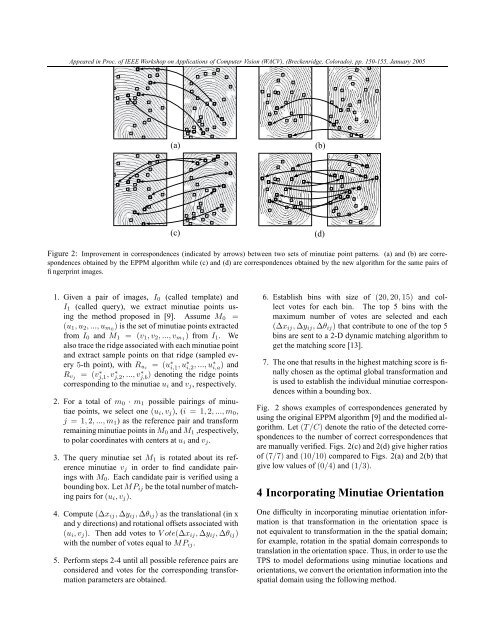
Appeared in Proc. of IEEE Workshop on Applications of Computer Vision (WACV), (Breckenridge, Colorado), pp. 150-155, January 2005(a)(b)(c)(d)Figure 2: Improvement in correspondences (indicated by arrows) between two sets of minutiae point patterns. (a) <strong>and</strong> (b) are correspondencesobtained by the EPPM algorithm while (c) <strong>and</strong> (d) are correspondences obtained by the new algorithm for the same pairs offingerprint images.1. Given a pair of images, I 0 (called template) <strong>and</strong>I 1 (called query), we extract minutiae points usingthe method proposed in [9]. Assume M 0 =(u 1 , u 2 , ..., u m0 ) is the set of minutiae points extractedfrom I 0 <strong>and</strong> M 1 = (v 1 , v 2 , ..., v m1 ) from I 1 . Wealso trace the ridge associated with each minutiae point<strong>and</strong> extract sample points on that ridge (sampled every5-th point), with R ui = (u ∗ i,1 , u∗ i,2 , ..., u∗ i,a ) <strong>and</strong>R vj = (vj,1 ∗ , v∗ j,2 , ..., v∗ j,b ) denoting the ridge pointscorresponding to the minutiae u i <strong>and</strong> v j , respectively.2. For a total of m 0 · m 1 possible pairings of minutiaepoints, we select one (u i , v j ), (i = 1, 2, ..., m 0 ,j = 1, 2, ..., m 1 ) as the reference pair <strong>and</strong> transformremaining minutiae points in M 0 <strong>and</strong> M 1 ,respectively,to polar coordinates with centers at u i <strong>and</strong> v j .3. The query minutiae set M 1 is rotated about its referenceminutiae v j in order to find c<strong>and</strong>idate pairingswith M 0 . Each c<strong>and</strong>idate pair is verified using abounding box. Let MP ij be the total number of matchingpairs for (u i , v j ).4. Compute (∆x ij , ∆y ij , ∆θ ij ) as the translational (in x<strong>and</strong> y directions) <strong>and</strong> rotational offsets associated with(u i , v j ). Then add votes to V ote(∆x ij , ∆y ij , ∆θ ij )with the number of votes equal to MP ij .5. Perform steps 2-4 until all possible reference pairs areconsidered <strong>and</strong> votes for the corresponding transformationparameters are obtained.6. Establish bins with size of (20, 20, 15) <strong>and</strong> collectvotes for each bin. The top 5 bins with themaximum number of votes are selected <strong>and</strong> each(∆x ij , ∆y ij , ∆θ ij ) that contribute to one of the top 5bins are sent to a 2-D dynamic matching algorithm toget the matching score [13].7. The one that results in the highest matching score is finallychosen as the optimal global transformation <strong>and</strong>is used to establish the individual minutiae correspondenceswithin a bounding box.Fig. 2 shows examples of correspondences generated byusing the original EPPM algorithm [9] <strong>and</strong> the modified algorithm.Let (T/C) denote the ratio of the detected correspondencesto the number of correct correspondences thatare manually verified. Figs. 2(c) <strong>and</strong> 2(d) give higher ratiosof (7/7) <strong>and</strong> (10/10) compared to Figs. 2(a) <strong>and</strong> 2(b) thatgive low values of (0/4) <strong>and</strong> (1/3).4 Incorporating <strong>Minutiae</strong> OrientationOne difficulty in incorporating minutiae orientation informationis that transformation in the orientation space isnot equivalent to transformation in the the spatial domain;for example, rotation in the spatial domain corresponds totranslation in the orientation space. Thus, in order to use theTPS to model deformations using minutiae locations <strong>and</strong>orientations, we convert the orientation information into thespatial domain using the following method.