Homogeneous LED-illumination using microlens arrays
Homogeneous LED-illumination using microlens arrays
Homogeneous LED-illumination using microlens arrays

Create successful ePaper yourself
Turn your PDF publications into a flip-book with our unique Google optimized e-Paper software.
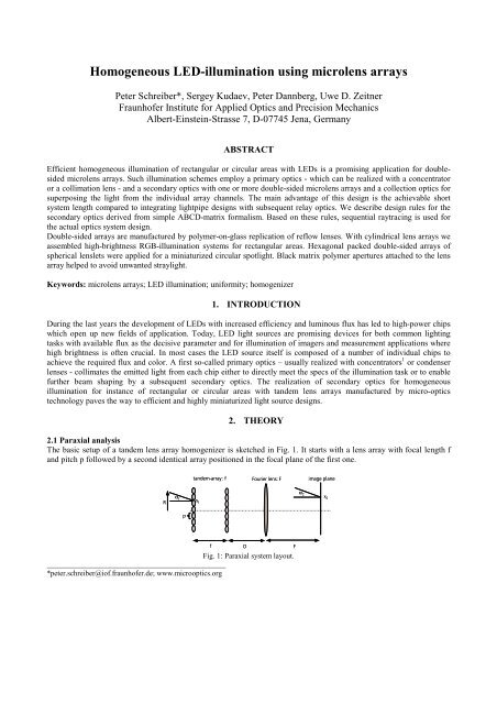
<strong>Homogeneous</strong> <strong>LED</strong>-<strong>illumination</strong> <strong>using</strong> <strong>microlens</strong> <strong>arrays</strong><br />
Peter Schreiber*, Sergey Kudaev, Peter Dannberg, Uwe D. Zeitner<br />
Fraunhofer Institute for Applied Optics and Precision Mechanics<br />
Albert-Einstein-Strasse 7, D-07745 Jena, Germany<br />
ABSTRACT<br />
Efficient homogeneous <strong>illumination</strong> of rectangular or circular areas with <strong>LED</strong>s is a promising application for doublesided<br />
<strong>microlens</strong> <strong>arrays</strong>. Such <strong>illumination</strong> schemes employ a primary optics - which can be realized with a concentrator<br />
or a collimation lens - and a secondary optics with one or more double-sided <strong>microlens</strong> <strong>arrays</strong> and a collection optics for<br />
superposing the light from the individual array channels. The main advantage of this design is the achievable short<br />
system length compared to integrating lightpipe designs with subsequent relay optics. We describe design rules for the<br />
secondary optics derived from simple ABCD-matrix formalism. Based on these rules, sequential raytracing is used for<br />
the actual optics system design.<br />
Double-sided <strong>arrays</strong> are manufactured by polymer-on-glass replication of reflow lenses. With cylindrical lens <strong>arrays</strong> we<br />
assembled high-brightness RGB-<strong>illumination</strong> systems for rectangular areas. Hexagonal packed double-sided <strong>arrays</strong> of<br />
spherical lenslets were applied for a miniaturized circular spotlight. Black matrix polymer apertures attached to the lens<br />
array helped to avoid unwanted straylight.<br />
Keywords: <strong>microlens</strong> <strong>arrays</strong>; <strong>LED</strong> <strong>illumination</strong>; uniformity; homogenizer<br />
1. INTRODUCTION<br />
During the last years the development of <strong>LED</strong>s with increased efficiency and luminous flux has led to high-power chips<br />
which open up new fields of application. Today, <strong>LED</strong> light sources are promising devices for both common lighting<br />
tasks with available flux as the decisive parameter and for <strong>illumination</strong> of imagers and measurement applications where<br />
high brightness is often crucial. In most cases the <strong>LED</strong> source itself is composed of a number of individual chips to<br />
achieve the required flux and color. A first so-called primary optics – usually realized with concentrators 1 or condenser<br />
lenses - collimates the emitted light from each chip either to directly meet the specs of the <strong>illumination</strong> task or to enable<br />
further beam shaping by a subsequent secondary optics. The realization of secondary optics for homogeneous<br />
<strong>illumination</strong> for instance of rectangular or circular areas with tandem lens <strong>arrays</strong> manufactured by micro-optics<br />
technology paves the way to efficient and highly miniaturized light source designs.<br />
2. THEORY<br />
2.1 Paraxial analysis<br />
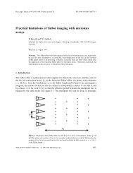
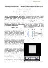
The basic setup of a tandem lens array homogenizer is sketched in Fig. 1. It starts with a lens array with focal length f<br />
and pitch p followed by a second identical array positioned in the focal plane of the first one.<br />
Fig. 1: Paraxial system layout.<br />
_______________________________________________<br />
*peter.schreiber@iof.fraunhofer.de; www.microoptics.org<br />
α 1<br />
x 1<br />
α 2<br />
x 2
After a distance D a bulk lens referred to as collector or Fourier lens with focal length F follows, which focuses and<br />
superposes the light from all channels of the tandem array in its focal plane. Equation (1) describes the tracing of an<br />
incoming ray with ray height x1 and angle of incidence α1 relative to the local coordinate system of the n-th array<br />
channel. After tracing through both lens <strong>arrays</strong> - described by the three matrices to the right - a coordinate break<br />
dx = -np, with p being the array pitch, is added, to change from the local coordinate system of the n-th array channel,<br />
with channel #0 being the central one, to the global coordinate system of the Fourier lens. Then the three matrices to the<br />
left trace the rays through the Fourier lens to the image plane.<br />
α<br />
x<br />
2<br />
2<br />
=<br />
1<br />
F<br />
0<br />
1<br />
1<br />
0<br />
1<br />
−<br />
F<br />
1<br />
1<br />
D<br />
0<br />
1<br />
Rearranging Eq. (1) leads to Eq. 2 giving simple expressions for ray height and angle in the image plane x2 and α2<br />
depending on the input ray parameters x1 and α1:<br />
α 2<br />
x2<br />
=<br />
x1<br />
f<br />
D 1<br />
−1<br />
− ( α1<br />
f − np)<br />
F F<br />
F<br />
− x1<br />
f<br />
(2)<br />
The bottom row of Eq. (2) describes the superposed imaging of the pupil plane of the lenslets of the first array with a<br />
magnification of –F/f, independent of the distance between tandem array and Fourier lens D. The upper row shows<br />
divergence in image space to be dependent from this distance. If we insert the maximum allowed half angle of incidence<br />
at the first lens array α1max equal to the lens array numerical aperture NAArray=p/2f - which is essential for correct<br />
operation of the array – and the maximum incoming ray height x1max equal to the half array pitch p/2, we arrive with the<br />
maximum radius of illuminated area x2max and the maximum divergence of <strong>illumination</strong> at the image plane α2max<br />
illuminated from the considered n-th array channel:<br />
α 2max<br />
x2max<br />
=<br />
p<br />
2 f<br />
D 1<br />
−1<br />
−<br />
F F<br />
F p<br />
− ⋅<br />
f 2<br />
p<br />
− np<br />
2<br />
(3)<br />
Analyzing Eq. (2) and (3) we can distinct between two cases:<br />
i. Minimum divergence of <strong>illumination</strong> requiring D=F. This case also ensures telecentric <strong>illumination</strong> of the<br />
image plane.<br />
ii. Minimum system length with D=0 enabling shortest system length, which has to be paid by increased<br />
divergence and non-telecentric <strong>illumination</strong>.<br />
Assuming a large number of illuminated lenslets i.e. the radius of the illuminated area at the first array R to be much<br />
larger than the array pitch, the resulting simple Equations (4a) and (4b) describe the maximum values for illuminated<br />
area size and divergence of <strong>illumination</strong> for the two cases of mimium divergence and minimum system length,<br />
respectively:<br />
≈<br />
F ⋅ NA<br />
F<br />
α 2max<br />
x2max R<br />
α 2max<br />
x2max ≈<br />
R<br />
NAarray<br />
+<br />
F<br />
F ⋅ NA<br />
(4a,b)<br />
array<br />
Analyzing Eq. (4a) with respect to etendue conservation, we see that the product of radius and divergence of both the<br />
incoming radiation as well as the illuminated area in the image plane is R⋅NAArray. Thus, for <strong>illumination</strong> of the<br />
homogenizer with a divergence exactly equal to the lens array numerical aperture NAArray, this setup can operate etendue<br />
conserving. If the incident light is less divergent, the homogenizer increases etendue, if the divergence of the incoming<br />
light is larger than the array NA crosstalk between neighboured lens array channels occurs, which lowers the useful<br />
transmission into the homogeneous illuminated area in the image plane and also prohibits etendue conservation. This<br />
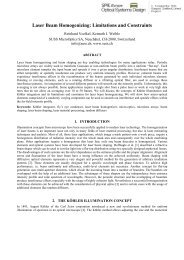
effect is shown in Fig 2 assuming collimated <strong>illumination</strong> of the tandem array under varying angles of incidence.<br />
For the short system length case shown in Eq. (4b) etendue conservation cannot be achieved.<br />
0<br />
− np<br />
+<br />
1<br />
0<br />
1<br />
−<br />
f<br />
1<br />
1<br />
f<br />
0<br />
1<br />
1<br />
0<br />
array<br />
1<br />
−<br />
f<br />
1<br />
α<br />
x<br />
1<br />
1<br />
(1)
Fig. 2: Crosstalk occurs for the upwards oriented collimated bundle with incidence angle larger than array NA.<br />
2.2 Aberrations<br />
One of the most significant advantages of tandem <strong>microlens</strong> array homogenizers is the short system length compared to<br />
systems consisting of integrating lightguides and relay optics. According to Eq. (4) the product of lens array NA and<br />
Fourier lens focal legth F determines the illuminated area size. Thus, to achieve short system length, high NA <strong>arrays</strong> are<br />
crucial to let this advantage become effective. On the other hand, large NA <strong>arrays</strong> produce aberrations, which decrease<br />
homogeneity and useful transmission. Analyzing the tandem lens array homogenizer by real raytracing, we can identify<br />
the most significant aberrations, which lead to loss of homogeneity, increased divergence of <strong>illumination</strong> in the image<br />
plane and loss of useful transmission. Both components of the homogenizer, the tandem array as well as the Fourier lens<br />
produce aberrations, but <strong>using</strong> sufficiently corrected Fourier lenses realized as doublets or aspherical singlets, the lens<br />
array is the dominating source of aberrations. Thus, we restrict this analysis to the center channel of the lens array. We<br />
assume identical lenslets on both sides of a common substrate and a ideal Fourier lens. These calculations are carried<br />
out with the raytracing software ZEMAX®. The analyzed system, modelling a monolithic PMMA tandem lens array<br />
and a Fourier lens modelled with the ZEMAX paraxial lens surface with 2mm focal length, is sketched in Fig. 3.<br />
Fig. 3: Real raytracing system layout.<br />
The results of the analysis are RMS spot size, distortion (Fig.4) and lateral color.<br />
Fig. 4: Real raytracing results: RMS spot size and distortion calculated for a tandem array with NA 0.2.
Because the size of the homogeneous illuminated area (image height) as well as spot size and lateral color scale with the<br />
focal length of the Fourier lens F, we normalize spot size and lateral color by the image height. Distortion is already<br />
normalized. The resulting normalized aberrations vs. tandem lens numerical aperture are shown in Fig. 5.<br />
[%]<br />
10<br />
8<br />
6<br />
4<br />
2<br />
RMS spot radius relative to image height<br />
Distortion<br />
Lateral color relative to image height<br />
RMS spot radius relative to image height (asphere)<br />
Distortion (asphere)<br />
LAteral color relative to image height (asphere)<br />
0<br />
0 0.1 0.2 0.3 0.4<br />
Lens array NA<br />
Fig. 5: Aberrations normalized to image height for spherical and aspherical PMMA lens array.<br />
From Fig. 5 the following informations are extracted:<br />
• Pincushion distortion - reaching about 10% for an array NA of 0.35 - is the dominant aberration, leading to a<br />
noticable drop of irradiance at the outer parts of the illuminated area.<br />
• The normalized RMS spot radius, which determines the sharpness of the rim of the illuminated area and so - to<br />
some extent - also the useful transmission into the homogeneous illuminated area, is only slightly smaller than<br />
distortion.<br />
• Lateral color with about 1% of image height has only a minor effect for array NA≥0.2.<br />
• Using simple conic aspheric lenslets decreases the spot size for array NA>0.25 but does not influence<br />
distortion significantly.<br />
Using higher refractive index material like polycarbonate, a slight decrease of both maximum distortion and spot size of<br />
about 1% occurs, but this has to be payed for with nearly doubled lateral color because of the larger dispersion of this<br />
material.<br />
2.3 Diffraction<br />
The <strong>illumination</strong> of the <strong>arrays</strong> with tempoaral and spatial incoherent <strong>LED</strong>-sources prevents the formation of interference<br />
patterns well-known from tandem lens array homogenizers for laser sources, but additional blurring is caused by<br />
diffraction effects at the lenslet apertures of the second array. The diffraction broadening in the image plane depends on<br />
the lenslet aperture i.e. the array pitch p, which determines the effective F/# of the Fourier lens for each array channel.<br />
We arrive with the diffraction limited spot radius shown in Eq. (5):<br />
F<br />
rdiff = 1.<br />
22 λ<br />
(5)<br />
p<br />
Analogous to the normalization used above we calculate the diffraction limited spot radius normalized to the image<br />
height:<br />
λ<br />
rdiffnorm = 1 . 22⋅<br />
(6)<br />
p ⋅ NA<br />
For typical array pitches of some 100µm, this results in a diffraction broadening of the illuminated area in the range of<br />
only 1% of image height. Only for <strong>arrays</strong> with small pitch and small NA this effect may become significant, because<br />
aberrations vanish in this case.
2.4 Straylight<br />
Light outside the blurred illuminated region in the image plane is considered as straylight. There are two main reasons<br />
which cause straylight:<br />
i. Crosstalk:<br />
Incoming light with angles of incidence larger than the array NA causes crosstalk between neighboured<br />
array channels (see Fig. 2). Aberrations of the first array may also lead to crosstalk even for <strong>illumination</strong><br />
angles smaller than the array NA.<br />
ii. Fillfactor:<br />
A limited fillfactor of the first array either from technological reasons – i.e. small transmittive regions<br />
between neighboured lenslets – or from array geometries which in principle cannot achieve 100% fillfactor<br />
like hexagonal packed circular lenslets results in illuminated regions near to the intendend spot and<br />
disturbes homogeneity of the actual spot.<br />
3. REALIZATION<br />
The realization of homogeneous light sources with tandem <strong>microlens</strong> array for rectangular and circular spot geometry<br />
shall be described in the following. Because this work is focused on the micro-optical components, we used a simple<br />
plano-convex Fourier lens, positioned near the array according to the minimum system length case. Different<br />
modifications of this scheme are possible:<br />
• Omitting the Fourier lens, which results in additional blurring of the homogeneous illuminated area equal to the<br />
radius of the illuminated area at the lens array R.<br />
• Changing the Fourier lens position to the minimum divergence case, which increases system length by the<br />
Fourier lens focal width F.<br />
• An equivalent realization of the minimum divergence case, which uses two lenses with focal width F, one near<br />
the array, the second in a distance F from the first one near the image plane. This modification exhibits smaller<br />
system length and lowers the working F/# of the Fourier lens(es), which results in reduced aberrations.<br />
• Using either aspheric Fourier lenses and/or plano-convex or biconvex doublets.<br />
3.1 Micro-optics technology<br />
The tandem lens <strong>arrays</strong> were manufactured by replication of lithographic structured reflow lenses into UV-curing<br />
polymer on both sides of float-glass substrates in a modified mask-aligner 2 (Fig. 6).<br />
polymer resin<br />
substrate<br />
alignment marks<br />
mask holder<br />
mould<br />
exposure gap<br />
chuck<br />
back side<br />
microscope<br />
Fig. 6: Double-sided replication of reflow lenses into UV-curing polymer on glass.<br />
The reflow master <strong>arrays</strong> are structured lithographically either to form cylindrical or hexagonal packed circular lenslets.<br />
The homogeneity of the curvature of the lenslets is about ±1%, the spaces between adjacent lenslets are in the range of<br />
only few microns. In a first replication step the convex reflow masters are inverted to form a concave array mould. This<br />
mould is used to replicate both sides of the tandem lens array in two consecutive moulding steps.<br />
A lateral alignment accuracy between the <strong>arrays</strong> on the two sides of the common substrate of ±5µm range can be<br />
achieved easily. The realized thickness precision of the tandem array is better than ±20µm. Paraxial and real raytracing<br />
simulations show these tolerances to be sufficient for <strong>illumination</strong>s purposes.
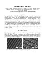
3.2 <strong>Homogeneous</strong> light source for rectangular illuminated area<br />
There are several possibilities to realize homogenizers for <strong>illumination</strong> of a rectangular area. The first approach uses a<br />
tandem array of densely packed, rectangular shaped spherical lenslets, while the other employs two consecutive tandem<br />
<strong>arrays</strong> of cylindrical lenslets. Because of difficulties associated with the manufacturing of high NA rectangular lenslets<br />
with small pitch, we used cylindrical lens <strong>arrays</strong>. The basic system layout is shown in Fig. 7.<br />
Fig. 7: Basic system layout for homogeneous <strong>illumination</strong> of a rectangular area.<br />
There are also two approaches <strong>using</strong> cylindrical tandem lens <strong>arrays</strong> for homogeneous <strong>illumination</strong> of rectangular areas:<br />
The <strong>arrays</strong> on both sides of a common substrate can be oriented either in parallel or orthogonal with respect to each<br />
other. The parallel type requires very precise alignment during array manufacturing and very little alignment during<br />
system assembly, while the orthogonal type shows contrary properties.<br />
Because of the precise replication in the mask aligner described above, we preferred the parallel arrangement of the two<br />
lens <strong>arrays</strong> type as shown in Fig. 7. We assembled two different homogenized light sources shown in Fig. 8:<br />
i. A small array NA light source <strong>using</strong> a Luxeon-V emitter, equipped with a Melles Griot glass condenser<br />
asphere for collimation and 2.2 mm thick cylindrical tandem <strong>arrays</strong> with 0.2 and 0.15 NA for horizontal<br />
and vertical direction, respectively.<br />
ii. A high array NA light source <strong>using</strong> a 4-chip OSTAR <strong>LED</strong>-module from OSRAM OS, equipped with a<br />
solid concentrator and cylindrical tandem lens <strong>arrays</strong> with 0.3 and 0.24 NA and thickness 0.8 and 1.2mm<br />
for horizontal and vertical direction, respectively.<br />
Fig. 8: <strong>Homogeneous</strong> <strong>illumination</strong> of rectangular areas: Small array NA light source (left) and high array NA light source (right).
Inspecting the achieved irradiance distributions, we see the effect of crosstalk for the first system ca<strong>using</strong> illuminated<br />
rectangles forming a cross around the actual illuminated area. The crosstalk arises from the small array NA in<br />
conjunction with the comparatively large remaining divergence of the Luxeon emitter collimated with the condenser<br />
asphere. The irradiance drops down to 90% at the edges of the illuminated area relative to the center irradiance.<br />
According to the larger array NA and the better collimation of the <strong>LED</strong> by the concentrator obtained with the second<br />
system, the illuminated rectangular area shows less straylight from crosstalk, but the large array NA produces strong<br />
pincushion distortion, which is cleary visible and deteriorates spot homogeneity remarkably. This results in only 72%<br />
irradiance at the corners of the illuminated rectangle. The measured irradiances at the margins and edges of the<br />
rectangular areas normalized to the center irradiance are listed in Tab. 1.<br />
System Array NA hor./vert. Norm. irradiance at Norm. irradiance at Norm. irradiance in the corner<br />
hor. margin vert. margin<br />
Small NA 0.2 / 0.15 92% 98% 90%<br />
Large NA 0.3 / 0.24 75% 85% 72%<br />
Tab. 1: Irradiance at margins and edge of the illuminated area normalized to the center irradiance.<br />
3.3 <strong>Homogeneous</strong> <strong>illumination</strong> of circular spots<br />
Because the tandem array homogenizer produces a magnified image of the first array´s lenslet aperture circular lenslets<br />
are required for realization of a circular illuminated spot. Unfortunately, even for hexagonal dense arrangement of such<br />
lenslets a fill factor – and also useful system transmission - in the range of only 90% can be achieved. Hexagonal<br />
packed tandem lens <strong>arrays</strong> with circular lenslets with a numerical aperture of 0.2 and 1.4mm thickness were<br />
manufactured with the technology described above.<br />
Irradiance [a.u.]<br />
1.0<br />
0.8<br />
0.6<br />
0.4<br />
0.2<br />
Scan through wings<br />
Scan through dark space between wings<br />
0<br />
-20 -10 0 10 20<br />
Angle [°]<br />
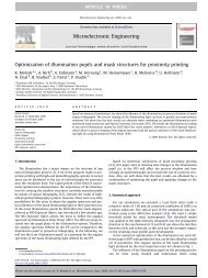
Fig. 9: Farfield of hexagonal arranged tandem lens array without apertures: Photo of farfield showing the actual spot surrounded by a<br />
wings forming a star-pattern (right) and scans (left).<br />
The resulting irradiance distribution in the image plane is shown in Fig. 9. The homogeneity of irradiance mainly suffers<br />
from two shortcomings:<br />
i. An irradiance peak in the center of the spot ca<strong>using</strong> a spot inhomogeneity of about 17%.<br />
ii. A star-shaped pattern surrounding the actual spot.<br />
Both effects are caused by light transmitted through the empty spaces between the circular lenslets: The peak arises<br />
from light arriving under nearly perpendicular incidence at the empty space of the first array and travelling straight<br />
through the corresponding empty space of the opposite array. The surrounding wings forming a star are caused by light<br />
incident under larger angles at the empty spaces of the first array arriving at the lenslets of the second array. With this
portion of the incident light the second array together with the Fourier lens form images of the empty spaces, which<br />
result in the star-pattern.<br />
To overcome these imperfections, we added a lithographic structured black polymer layer between the first array layer<br />
and the glass substrate to achieve monolithic tandem <strong>arrays</strong> with integrated circular apertures (Fig 10).<br />
Fig. 10: Microscopic image of the lenslets of the first array surrounded by black matrix polymer apertures (left)<br />
and diced tandem <strong>arrays</strong> with integrated apertures (right).<br />
We built a homogenized light source consisting of a RGGB OSTAR-module, equipped with a reflective/refractive<br />
concentrator, a 0.2NA monolithic tandem lens array with integrated apertures and a plano-convex collecting lens. The<br />
resulting spot is shown in Fig. 11. The blocking of light formerly travelling through the spaces between the lenslets by<br />
the integrated apertures effectively prevents the formation the star-pattern visible in Fig. 9. Position-dependent color<br />
deviations of the mixed white are nearly imperceptible in the spot. Only in the surrounding ghost-spots, which originate<br />
from crosstalk, color separation occurs because of the angular separation of the light radiated from the individual <strong>LED</strong>chips<br />
in the farfield of the concentrator.<br />
Fig. 11: <strong>Homogeneous</strong> illuminated circular spot surrounded by weak ghost images.<br />
We measured a decrease of irradiance at the rim of the spot of 89% with respect to irradiance at the center. The<br />
intensity in the surrounding ghosts is well below 1% of the actual spot.<br />
CONCLUSION<br />
The use of tandem <strong>microlens</strong> <strong>arrays</strong> - optionally equipped with integrated black matrix polymer apertures – together<br />
with high-power <strong>LED</strong>s equipped with concentrators enables the realization of efficient light sources for homogeneous
<strong>illumination</strong> of rectangular or circular areas. Compared to traditional approaches like integrating lightguides with<br />
subsequent relay optics, these light sources offer very short system length in the range of only some cm together with<br />
good homogeneity and high useful transmission up to <strong>microlens</strong> array numerical apertures of about 0.2 … 0.25. The<br />
manufacturing of the tandem <strong>arrays</strong> by polymer-on-glass replication of lithographic structured reflow lenses offers the<br />
required precision to obtain good spot homogeneity, which is mainly limited by distortion.<br />
ACKNOW<strong>LED</strong>GEMENT<br />
This work was sponsored by the German Federal Ministry for Education and Research (BMBF) under contract number<br />
13N8271. The authors wish to thank Georg Bogner and Stefan Grötsch from Osram OS for supplying the <strong>LED</strong>-modules<br />
and Heike Schmidt from Fraunhofer IOF for characterization of the light sources and continuous help during<br />
preparation of this work.<br />
REFERENCES<br />
1. S. Kudaev, P. Schreiber, “Optimisation of symmetrical free-shape non-imaging concentrators for <strong>LED</strong> light source<br />
applications”, Proc. SPIE, to be published.<br />
2. P. Dannberg, G. Mann, L. Wagner, A. Bräuer, “Polymer UV-moulding for micro-optical systems and O/Eintegration”,<br />
Proc. SPIE 4179 (2000), pp. 137-45.