Optimization of illumination pupils and mask structures for proximity ...
Optimization of illumination pupils and mask structures for proximity ...
Optimization of illumination pupils and mask structures for proximity ...

You also want an ePaper? Increase the reach of your titles
YUMPU automatically turns print PDFs into web optimized ePapers that Google loves.
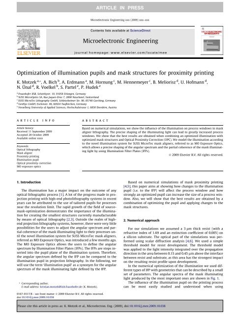
<strong>Optimization</strong> <strong>of</strong> <strong>illumination</strong> <strong>pupils</strong> <strong>and</strong> <strong>mask</strong> <strong>structures</strong> <strong>for</strong> <strong>proximity</strong> printing<br />
K. Motzek a, *, A. Bich b , A. Erdmann a , M. Hornung c , M. Hennemeyer c , B. Meliorisz d , U. H<strong>of</strong>mann d ,<br />
N. Ünal d , R. Voelkel b , S. Partel e , P. Hudek e<br />
a<br />
Fraunh<strong>of</strong>er IISB, Schottkystr. 10, 91058 Erlangen, Germany<br />
b<br />
SUSS MicroOptics SA, Rue Jaquet-Droz 7, 2000 Neuchatel, Switzerl<strong>and</strong><br />
c<br />
SUSS MicroTec Lithography GmbH, Schleissheimer Str. 90, 85748 Garching, Germany<br />
d<br />
GenISys GmbH, Eschenstr. 66, 82024 Taufkirchen, Germany<br />
e<br />
Vorarlberg University <strong>of</strong> Applied Sciences, Hochschulstrasse 1, 6850 Dornbirn, Austria<br />
article info<br />
Article history:<br />
Received 11 September 2009<br />
Accepted 28 October 2009<br />
Available online xxxx<br />
Keywords:<br />
Optical lithography<br />
Mask aligner<br />
Proximity printing<br />
Illumination pupil<br />
Optical <strong>proximity</strong> correction<br />
MO exposure optics<br />
1. Introduction<br />
abstract<br />
The <strong>illumination</strong> has a major impact on the outcome <strong>of</strong> any<br />
optical lithographic process [1]. A lot <strong>of</strong> the progress made in projection<br />
printing with high-end photolithography systems in recent<br />
years can be attributed to the use <strong>of</strong> tailored <strong>pupils</strong> <strong>for</strong> processes<br />
near the resolution limit. The rapid growth <strong>of</strong> the field <strong>of</strong> source<strong>mask</strong>-optimization<br />
demonstrates the importance <strong>of</strong> the <strong>illumination</strong><br />
<strong>for</strong> creating the smallest <strong>structures</strong> currently manufacturable<br />
by means <strong>of</strong> optical lithography [2,3]. Outside the realm <strong>of</strong> highend<br />
projection lithography systems, however, there were very little<br />
possibilities <strong>for</strong> the users to adjust the angular spectrum <strong>and</strong> partial<br />
coherence <strong>of</strong> the <strong>mask</strong> illuminating light to their processes until<br />
the novel <strong>illumination</strong> system <strong>for</strong> SUSS MicroTec <strong>mask</strong> aligners,<br />
referred as MO Exposure Optics, was introduced a few months ago.<br />
The MO Exposure Optics allows the users to define the angular<br />
spectrum by Illumination Filter Plates (IFPs). The IFPs are stops inserted<br />
into the pupil plane <strong>of</strong> the <strong>illumination</strong> system. There<strong>for</strong>e,<br />
the angular spectrum defined by the IFP can be compared to the<br />
<strong>illumination</strong> pupil in projection lithography. In the following, we<br />
will use the term ‘<strong>illumination</strong> pupil’ as a synonym <strong>for</strong> the angular<br />
spectrum <strong>of</strong> the <strong>mask</strong> illuminating light defined by the IFP.<br />
* Corresponding author.<br />
E-mail address: kristian.motzek@iisb.fraunh<strong>of</strong>er.de (K. Motzek).<br />
0167-9317/$ - see front matter Ó 2009 Elsevier B.V. All rights reserved.<br />
doi:10.1016/j.mee.2009.10.038<br />
ARTICLE IN PRESS<br />
Microelectronic Engineering xxx (2009) xxx–xxx<br />
Contents lists available at ScienceDirect<br />
Microelectronic Engineering<br />
journal homepage: www.elsevier.com/locate/mee<br />
Based on numerical simulations, we show the influence <strong>of</strong> the <strong>illumination</strong> on process windows in <strong>mask</strong><br />
aligner lithography. The precise shaping <strong>of</strong> the illuminating light can lead to greatly increased process<br />
windows. We show that the best results are obtained when combining an optimized <strong>illumination</strong> with<br />
optimized <strong>mask</strong> <strong>structures</strong> <strong>and</strong> Optical Proximity Correction (OPC). We model the <strong>illumination</strong> according<br />
to the novel <strong>illumination</strong> system <strong>for</strong> SUSS MicroTec <strong>mask</strong> aligners, referred to as MO Exposure Optics,<br />
which allows a precise shaping <strong>of</strong> the angular spectrum <strong>and</strong> the partial coherence <strong>of</strong> the <strong>mask</strong> illuminating<br />
light by using Illumination Filter Plates (IFPs).<br />
Ó 2009 Elsevier B.V. All rights reserved.<br />
Based on numerical simulations <strong>of</strong> <strong>mask</strong> <strong>proximity</strong> printing<br />
[4,5], this paper aims at showing how changes to the <strong>illumination</strong><br />
pupil (i.e. to the IFP) will affect the process window <strong>and</strong> how<br />
strongly an optimized pupil can increase the size <strong>of</strong> a process window.<br />
Also, we will show that the best results are obtained by a<br />
combination <strong>of</strong> optimizing the pupil <strong>and</strong> applying changes to the<br />
<strong>mask</strong> <strong>structures</strong>.<br />
2. Numerical approach<br />
Please cite this article in press as: K. Motzek et al., Microelectron. Eng. (2009), doi:10.1016/j.mee.2009.10.038<br />
For our simulations we assumed a 3 lm thick resist (with a<br />
refractive index <strong>of</strong> 1.69 <strong>and</strong> an extinction coefficient <strong>of</strong> 0.005) on<br />
a silicon substrate. The optical part <strong>of</strong> the simulations was per<strong>for</strong>med<br />
using scalar diffraction analysis [4,6]. We used a simple<br />
threshold model <strong>for</strong> resist development. The threshold model<br />
was applied to the light intensity integrated over the propagation<br />
direction in the area between 0.15 <strong>and</strong> 0.45 lm above the interface<br />
between resist <strong>and</strong> substrate, as this area has the strongest impact<br />
on the resulting resist pr<strong>of</strong>ile upon development.<br />
In the numerical optimization <strong>of</strong> the <strong>illumination</strong> we used different<br />
types <strong>of</strong> IFP with geometries that can be described by a small<br />
set <strong>of</strong> parameters. The angular spectra <strong>of</strong> the <strong>mask</strong> illuminating<br />
light produced by the most important ones are shown in Fig. 1.<br />
The influence <strong>of</strong> the <strong>illumination</strong> pupil on the printing process<br />
can be most easily studied <strong>and</strong> understood when using
monochromatic light. All simulations were there<strong>for</strong>e per<strong>for</strong>med<br />
assuming a monochromatic light source <strong>of</strong> wavelength 365 nm.<br />
3. Results<br />
( a)<br />
(c)<br />
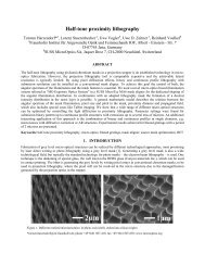
Fig. 1. The pictures show the angular spectra <strong>of</strong> the <strong>mask</strong> illuminating light<br />
produced by the different types <strong>of</strong> IFPs we tested in the optimization process. We<br />
use the transverse components <strong>of</strong> the light’s wave vector (kx <strong>and</strong> ky) to describe the<br />
<strong>illumination</strong> angles. (a) shows a pupil that contains light only where the modulus <strong>of</strong><br />
kx lies between a minimal value kmin <strong>and</strong> a maximal value kmax (indicated by the<br />
arrows). The annular IFP in (b) contains light only where the modulus <strong>of</strong> the<br />
transverse wave vector ðk 2<br />
x<br />
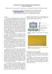
The first problem we investigated was the printing <strong>of</strong> 2 lm<br />
wide bright lines with a semi-dense pitch <strong>of</strong> 8 lm at a <strong>proximity</strong><br />
gap around 20 lm. The difficulties encountered when trying to<br />
print such lines using a <strong>mask</strong> that consists <strong>of</strong> 2 lm bright lines<br />
can be explained by taking a look at Fig. 2. Fig. 2a shows the intensity<br />
pr<strong>of</strong>ile obtained with a plane wave <strong>illumination</strong> at a <strong>proximity</strong><br />
gap <strong>of</strong> 20 lm. The multitude <strong>of</strong> local minima <strong>and</strong> maxima caused<br />
( b)<br />
þ k2<br />
y Þ1=2 lies between k min <strong>and</strong> k max. The IFP shown in (c)<br />
is described by three parameters: the inner (ri) <strong>and</strong> outer radius (ro) <strong>of</strong> the ring are<br />
modulated over the azimuth like ri(u)=kmin(1 + ncos(4u)) <strong>and</strong> ro(u)=kmax(1 + ncos(4u)),<br />
where n is a measure <strong>for</strong> the deviation from the annular <strong>for</strong>m.<br />
(a)<br />
(b)<br />
µ µ<br />
(c)<br />
Fig. 2. (a) Shows the intensity pr<strong>of</strong>ile at a <strong>proximity</strong> gap <strong>of</strong> 20 l m obtained with a<br />
<strong>mask</strong> consisting <strong>of</strong> 2 lm semi-dense lines using a plane wave as <strong>illumination</strong>. Using<br />
an optimized IFP, the intensity pr<strong>of</strong>ile looks more favorable, as shown in (b). The<br />
process window obtained when using the optimized IFP is shown in (c).<br />
µ<br />
ARTICLE IN PRESS<br />
2 K. Motzek et al. / Microelectronic Engineering xxx (2009) xxx–xxx<br />
Please cite this article in press as: K. Motzek et al., Microelectron. Eng. (2009), doi:10.1016/j.mee.2009.10.038<br />
by diffraction makes it impossible to print 2 lm lines with such<br />
a configuration.<br />
We used an optimization algorithm to look <strong>for</strong> an IFP that<br />
would generate the biggest possible process window <strong>for</strong> a <strong>mask</strong><br />
with 2 lm lines. The process window is defined as the maximum<br />
dose variation that will produce results within specification [4]<br />
(it is commonly assumed that a structure is within specification<br />
if it does not deviate more than 10% from the targeted size). The<br />
robustness <strong>of</strong> a process against dose variations is important, because<br />
the dose can only be controlled with a certain precision<br />
<strong>and</strong> because the dose varies over the wafer due to inhomogeneities<br />
in the <strong>illumination</strong> system. Since not only the dose but also the<br />
<strong>proximity</strong> gap can only be controlled with a certain precision, a robust<br />
process needs to allow dose variations over a range <strong>of</strong> gaps.<br />
We assumed that the <strong>proximity</strong> gap can be controlled with a precision<br />
<strong>of</strong> ±2 lm <strong>and</strong> there<strong>for</strong>e calculated the process window between<br />
18.0 <strong>and</strong> 22.0 lm.<br />
The type <strong>of</strong> IFP we optimized is shown in Fig. 1a. As a result <strong>of</strong><br />
the optimization, we obtained values <strong>for</strong> kmax <strong>of</strong> 25 mrad <strong>and</strong> <strong>for</strong><br />
kmin <strong>of</strong> 0 mrad (i.e. the two bright stripes in Fig. 1a merge into<br />
one). The intensity pr<strong>of</strong>ile at a <strong>proximity</strong> gap <strong>of</strong> 20 lm obtained<br />
with that IFP is shown in Fig. 2b <strong>and</strong> the process window is shown<br />
in Fig. 2c. Doses in Fig. 2c were normalized to the optimum dose <strong>for</strong><br />
that process. The process window is the area between the two dotted<br />
horizontal lines. The maximum dose variations allowed are less<br />
than 1%. Under realistic conditions such a process is there<strong>for</strong>e<br />
infeasible.<br />
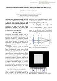
To obtain a better process window, we next optimized not only<br />
the pupil, but also the width <strong>of</strong> the lines on the <strong>mask</strong>. Again, the<br />
type <strong>of</strong> IFP optimized is shown in Fig. 1a. We now have to optimize<br />
three parameters simultaneously: two parameters (k max <strong>and</strong> k min)<br />
describing the IFP <strong>and</strong> the line width on the <strong>mask</strong>. Our optimization<br />
algorithm found the largest process window <strong>for</strong> a linewidth<br />
<strong>of</strong> 2.9 lm on the <strong>mask</strong> <strong>and</strong> a pupil with kmax = 45 mrad <strong>and</strong><br />
k min = 0 mrad.<br />
Fig. 3a shows the intensity pr<strong>of</strong>ile produced with a <strong>mask</strong> with<br />
2.9 lm lines at a <strong>proximity</strong> gap <strong>of</strong> 20 lm using a plane wave as<br />
<strong>illumination</strong>. It is not suitable <strong>for</strong> printing 2 lm lines either. However,<br />
Fig. 3b shows the pr<strong>of</strong>ile obtained when using the optimized<br />
IFP <strong>and</strong> Fig. 3c shows the resulting process window. Here, dose<br />
variations <strong>of</strong> ±7% are allowed, making it much more likely that<br />
such a process could work in reality.<br />
( a)<br />
(c)<br />
( b)<br />
µ µ<br />
Fig. 3. (a) Shows the intensity pr<strong>of</strong>ile at a <strong>proximity</strong> gap <strong>of</strong> 20 lm obtained with a<br />
<strong>mask</strong> consisting <strong>of</strong> 2.9 lm lines <strong>and</strong> a pitch <strong>of</strong> 8 lm using a plane wave as<br />
<strong>illumination</strong>. The intensity pr<strong>of</strong>ile obtained when using an optimized IFP is shown<br />
in (b). The corresponding process window is shown in (c).<br />
µ
Our next aim was to print 5 lm posts with a pitch <strong>of</strong> 20 lm at<br />
<strong>proximity</strong> gaps around 33 lm. To calculate a process window, we<br />
defined that any result would be within specification if the footprint<br />
<strong>of</strong> the post lies entirely between a square <strong>of</strong> 4.5 lm <strong>and</strong> a<br />
square <strong>of</strong> 5.5 lm edge length.<br />
Again, the simulations show that a plane wave <strong>illumination</strong><br />
would not be suitable <strong>for</strong> printing posts <strong>of</strong> that size at this relatively<br />
large <strong>proximity</strong> gap. We there<strong>for</strong>e used the type <strong>of</strong> IFP shown<br />
in Fig. 1b <strong>and</strong> optimized the values <strong>of</strong> kmin <strong>and</strong> kmax, describing the<br />
inner <strong>and</strong> outer radius <strong>of</strong> the annulus.<br />
First, we assumed an ‘unoptimized’ <strong>mask</strong>, i.e. the <strong>mask</strong> looks<br />
like the structure we are trying to print (5 lm squares with a pitch<br />
<strong>of</strong> 20 lm). With the <strong>mask</strong> being fixed, we only have two parameters<br />
to optimize: k min <strong>and</strong> k max. We found the largest process window<br />
<strong>for</strong> kmin = 40 mrad <strong>and</strong> kmax = 55 mrad.<br />
To demonstrate the importance <strong>of</strong> choosing the right IFP on the<br />
result <strong>of</strong> the printing process, Fig. 4a shows the footprint <strong>of</strong> the<br />
post at a <strong>proximity</strong> gap <strong>of</strong> 33 lm obtained when using a ‘wrong’<br />
IFP with kmin = 0 mrad <strong>and</strong> kmax = 55 mrad. (Note that this results<br />
in an angular spectrum <strong>of</strong> the <strong>mask</strong> illuminating light similar to<br />
the one currently used in many <strong>mask</strong> aligner systems.) The footprint<br />
<strong>of</strong> the post obtained when using the optimized IFP is shown<br />
in Fig. 4b. It resembles much more the square pr<strong>of</strong>ile that we targeted<br />
at. The process window with optimized IFP is shown in<br />
Fig. 4c.<br />
Again, we can increase the size <strong>of</strong> the process window considerably<br />
if we modify the <strong>structures</strong> on the <strong>mask</strong>. Varying the size <strong>of</strong><br />
the squares on the <strong>mask</strong> did not have any beneficial effects. Instead,<br />
we used assist <strong>structures</strong> to come to bigger process windows.<br />
Inspired by the rules <strong>for</strong> optical <strong>proximity</strong> correction (OPC)<br />
in projection lithography, we added little squares at the corners<br />
<strong>of</strong> our 5 lm square <strong>and</strong> optimized the size <strong>of</strong> these assist <strong>structures</strong><br />
together with the parameters describing the IFP. The result we got<br />
was the <strong>mask</strong> structure shown in Fig. 5d. The type <strong>of</strong> IFP used in<br />
the optimization is shown in Fig. 1c (in fact, Fig. 1c shows the optimized<br />
pupil). The parameters we obtained <strong>for</strong> the pupil were<br />
k min = 35 mrad, k max = 57 mrad <strong>and</strong> n = 0.11.<br />
µ<br />
(a)<br />
µ<br />
(c)<br />
Fig. 4. The figures show the simulation results <strong>of</strong> printing 5 lm posts with an<br />
‘unoptimized’ <strong>mask</strong>. The solid line in (a) shows the footprint obtained at a<br />
<strong>proximity</strong> gap <strong>of</strong> 33 lm when using an annular IFP that has not been optimized<br />
either. (Here, kmin = 0 mrad <strong>and</strong> kmax = 55 mrad.) The dashed square is the 5 lm<br />
square we want to print. The footprint obtained when using the optimized IFP<br />
(k min = 40 mrad <strong>and</strong> k max = 55 mrad) is shown in (b). The corresponding process<br />
window is shown in (c).<br />
µ<br />
(b)<br />
µ<br />
µ<br />
ARTICLE IN PRESS<br />
K. Motzek et al. / Microelectronic Engineering xxx (2009) xxx–xxx 3<br />
( a)<br />
Again, to emphasize the importance <strong>of</strong> the IFP, we calculated<br />
the footprint <strong>of</strong> the post at 33 lm using a wrong IFP (annular with<br />
kmin = 0 mrad <strong>and</strong> kmax = 55 mrad). Fig. 5a shows that the footprint<br />
strongly deviates from the targeted square pr<strong>of</strong>ile, despite the assist<br />
<strong>structures</strong> on the <strong>mask</strong>. When using the optimized IFP the footprint<br />
<strong>of</strong> the post is an almost perfect 5 lm square, as shown in<br />
Fig. 5b. The process window <strong>for</strong> the optimized solution is shown<br />
in Fig. 5c.<br />
The comparison between the process windows <strong>and</strong> footprints in<br />
Figs. 4 <strong>and</strong> 5a <strong>and</strong> b show the benefit <strong>of</strong> using OPC <strong>structures</strong> to the<br />
<strong>mask</strong>. However, this means that we have to parameterize the<br />
shape <strong>of</strong> the pupil <strong>and</strong> the <strong>structures</strong> on the <strong>mask</strong> <strong>and</strong> that the<br />
number <strong>of</strong> parameters included in our optimization increases. Future<br />
investigations will have to show how many free parameters<br />
are really needed in the optimization to come to satisfying results.<br />
4. Conclusion<br />
In conclusion, we have shown the essential role <strong>of</strong> the <strong>illumination</strong><br />
pupil <strong>for</strong> <strong>mask</strong> aligner lithography <strong>and</strong> how the adequate<br />
choice <strong>of</strong> an IFP can open process windows that are otherwise<br />
non-existent. Even more powerful is the combination <strong>of</strong> OPC <strong>and</strong><br />
an optimized IFP.<br />
To use our numerical findings practically, one will have to take<br />
into consideration in much detail the properties <strong>of</strong> the light source,<br />
the bleaching <strong>of</strong> the resist <strong>and</strong> possibly other effects as well. An indepth<br />
investigation <strong>of</strong> these effects as well as the extension <strong>of</strong> the<br />
results presented here to more complicated <strong>structures</strong> <strong>and</strong> <strong>pupils</strong><br />
<strong>and</strong> the comparison with experimental data is a task that will most<br />
probably help to extend the limits <strong>of</strong> <strong>mask</strong> aligner lithography.<br />
Acknowledgments<br />
Please cite this article in press as: K. Motzek et al., Microelectron. Eng. (2009), doi:10.1016/j.mee.2009.10.038<br />
µ<br />
( c)<br />
( b)<br />
( d)<br />
The authors would like to thank the Bayerische Forschungsstiftung<br />
<strong>for</strong> funding this work in the framework <strong>of</strong> the project ‘‘MALS”.<br />
µ<br />
µ µ<br />
µ<br />
Fig. 5. The figures show the simulation results <strong>of</strong> printing 5 l m posts with an<br />
optimized <strong>mask</strong>. The solid line in (a) shows the footprint obtained at a <strong>proximity</strong><br />
gap <strong>of</strong> 33 lm when using the optimized <strong>mask</strong> layout without using the cooptimized<br />
IFP. The footprint obtained when using the optimized IFP is shown in (b).<br />
The corresponding process window is shown in (c). The optimized <strong>mask</strong> structure is<br />
shown in (d). It consists <strong>of</strong> a large square with edge length 5 lm <strong>and</strong> four small<br />
squares <strong>of</strong> edge length 1.2 l m centered around the corners <strong>of</strong> the big square.
References<br />
[1] A.E. Rosenbluth, S. Bukowski, M. Hibbs, K. Lai, A. Molles, R. Singh, A.K. Wong,<br />
Proc. SPIE 4346 (2001) 486.<br />
[2] T. Fühner, S. Popp, C. Dürr, A. Erdmann, Proc. SPIE 6154 (2006) 1269.<br />
[3] A.E. Rosenbluth, D.O. Melville, K. Tian, S. Bagheri, J. Tirapu-Azpiroz, K. Lai, A.<br />
Waechter, T. Inoue, L. Ladanyi, F. Barahona, K. Scheinberg, M. Sakamoto, H.<br />
ARTICLE IN PRESS<br />
4 K. Motzek et al. / Microelectronic Engineering xxx (2009) xxx–xxx<br />
Please cite this article in press as: K. Motzek et al., Microelectron. Eng. (2009), doi:10.1016/j.mee.2009.10.038<br />
Muta, E. Gallagher, T. Faure, M. Hibbs, A. Tritchkov, Y. Granik, Proc. SPIE 7274<br />
(2009) 727409.<br />
[4] B. Meliorisz, P. Evanschitzky, A. Erdmann, Microelectron. Eng. 84 (2007)<br />
733.<br />
[5] W. Henke, M. Weiss, R. Schwalm, J. Pelka, Microelectron. Eng. 10 (1990)<br />
127.<br />
[6] J.D. Jackson, Classical Electrodynamics, John Wiley <strong>and</strong> Sons, 1975.