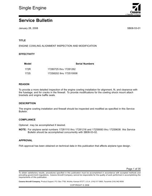
SB 08-53-01 - McFarlane Aviation Products
SB 08-53-01 - McFarlane Aviation Products
SB 08-53-01 - McFarlane Aviation Products
You also want an ePaper? Increase the reach of your titles
YUMPU automatically turns print PDFs into web optimized ePapers that Google loves.
NAS1149FN232P Washer, Baffle Seal (as necessary)P840306 Tape, Polyurethane (approx 12 ft)S1021Z8-8 Screw, Align Tool 4 / toolS1438-41 Washer, Nylon 8 (if necessary)S2319C4 Fastener, 1/4 Turn (as necessary)S2319C5 Fastener, 1/4 Turn (as necessary)S2319C6 Fastener, 1/4 Turn (as necessary)S2319C7 Fastener, 1/4 Turn (as necessary)S2319C8 Fastener, 1/4 Turn (as necessary)S2319C9 Fastener, 1/4 Turn (as necessary)S2319-65 Grommet, 1/4 Turn Fastener (as necessary)S2319-66 Grommet, 1/4 Turn Fastener (as necessary)S3806-9 .032 Alclad Aluminum (to make upper nose (as necessary)cap reinforcement plates)S3881-3 Washer, Countersunk 8U074093 Marker, Alodine 1132 (as necessary)0552212-245 Cowl Assembly, Upper 1 (if necessary)0552227-1 Shim, Shock Mount (if/as necessary)0555250-17 Seal, Baffle 10555250-18 Seal, Baffle 10555250-19 Seal, Baffle 10555259-25 Seal, Baffle 10555259-26 Seal, Baffle 10555259-27 Seal, Baffle 10591009-2 Adjustment Plate, Shock Mount 20Parts For Firewall Repair05<strong>53</strong>031-3 Firewall Assembly, Lower 1 (if necessary)MS21042-06 Nut, Firewall Repair (if/as necessary)MS21042-<strong>08</strong> Nut, Firewall Repair (if/as necessary)MS35206-226 Screw, Firewall Repair (if/as necessary)MS35206-241 Screw, Firewall Repair (if/as necessary)U00<strong>01</strong>17S Sealant (200 Gram) (if/as necessary)MS20427M4-5 Rivet (if/as necessary)MS20427M5-5 Rivet (if/as necessary)MS20470AD4-4A Rivet (if/as necessary)MS20615-4M4 Rivet (if/as necessary)MS20615-4M5 Rivet (if/as necessary)<strong>SB</strong><strong>08</strong>-<strong>53</strong>-<strong>01</strong>January 28, 20<strong>08</strong> Page 3
To receive credit, the work must be completed and a Warranty Claim submitted by a Cessna Single EngineService Station within 30 calendar days of Service Bulletin compliance before the credit expiration datesshown below.NOTE: For airplanes that require replacement of the lower firewall assembly, the removed firewall shall beheld for field scrap per standard procedures.NOTE: For airplanes that require replacement of the upper cowl, the removed cowl shall be held for fieldscrap per standard procedures.Domestic ................... January28,2009International ................. January28,2009Special Note to Service Stations:When you complete the Warranty Claim, the labor allowance claimed shall be itemized for each above actioncompleted.ACCOMPLISHMENT INSTRUCTIONSWeight And Balance InformationNegligibleMaterial InformationThe parts listed below may be necessary.NEW P/N QUANTITY DESCRIPTION OLD P/N DISPOSITIONAN525-10R10 8 Screw NoneAN525-832R6 22 Screw NoneAN528-832R8 As necessary Screw Same DiscardJ7444-42 As necessary Shock Mount Same DiscardMS20426AD3-2A 16 Rivet Staple DiscardMS20426A3-4A 46 Rivet NoneMS21042L<strong>08</strong> 40 Nut NoneMS21059L3K 8 Nutplate NoneMS24693S48 20 Screw NoneMS24693S50 20 Screw NoneMS24694C52 8 Screws NoneMS21042L<strong>08</strong> 40 Nut NoneMS21059L3K 8 Nutplate NoneMS24693S48 20 Screw NoneMS24693S50 20 Screw NoneMS24694C52 8 Screws NoneNAS1149FN232P As necessary Washer NoneP840306 1 Polyurethane tape NoneS1021Z8-8 As necessary Screw None<strong>SB</strong><strong>08</strong>-<strong>53</strong>-<strong>01</strong>January 28, 20<strong>08</strong> Page 5
05<strong>53</strong>031-3 1 Firewall, LowerAssemblySameDiscardNote 1: MS20427M4-5 and MS20615-4M4 Rivets are standard rivets to install the 05<strong>53</strong>031-3 Lower FirewallAssembly. If the rivet hole size is larger than 0.138-inch diameter, use MS20427M5-5 and MS20615-5M4Rivets as necessary.The materials or equivalent that follow may be necessary:NAME NUMBER MANUFACTURER USECorrosion ResistantPrimerK000912Cessna AircraftCompanyCessna Parts Distribution5800 East PawneePO Box 1521Wichita, KS 67218Alodine 1132 Marker U074093 Cessna AircraftCompanyCessna Parts Distribution5800 East PawneePO Box 1521Wichita, KS 67218CMNP009 Sealant U00<strong>01</strong>17S (200 gram) Cessna AircraftCompanyCessna Parts Distribution5800 East PawneePO Box 1521Wichita, KS 672180.032-inch AlcladAluminum0.<strong>01</strong>6-inch StainlessSteelPlywood, 0.50-inchthickness (alternate is0.375 inch)2024-T3 or S3806-9 Purchase locallyor purchase from:Cessna AircraftCompanyCessna Parts Distribution5800 East PawneePO Box 1521Wichita, KS 672183<strong>01</strong> annealed stainlesssteel per MIL-S-5059or equivalent. Alternatematerial, 302 or 304annealed stainless steelsheet per AMS5516 orequivalentPurchase locallyPurchase locallyTo apply to bare metalTo apply to bare metalSealant for the firewallTo make the nutplatereinforcement plates forthe upper nose capTo make firewall repairdoublerTo make the nose capalignment fixture0.040-inch Aluminum 2024-T3 Purchase locally To make the nose capalignment fixture attachanglesNylon Webbing, Rope, orShock CordPurchase locallyTo attach the nose capalignment fixture to thepropeller<strong>SB</strong><strong>08</strong>-<strong>53</strong>-<strong>01</strong>January 28, 20<strong>08</strong> Page 7
Instructions1. Electrically ground the airplane and turn all switches to the "OFF" position. If external power is connectedto the airplane, disconnect external power from receptacle.2. Remove the upper engine cowling and disconnect the airplane battery. (Refer to the Model 172 Series1996 and On Maintenance Manual, Chapter 24, Electrical Power.)3. Attach maintenance warning tags to the battery and external power receptacle with the followinginstruction: DO NOT CONNECT ELECTRICAL POWER - MAINTENANCE IN PROGRESS.4. Do the inspection steps below with the upper and lower cowling installed.A. Install the upper engine cowling.B. Look inside the oil door and the APU door and do an inspection for the condition of each shockmount.NOTE: Table 1, Cowling Fit Dimensions is available for you to record measurements and analyzethe total cowling to fuselage fit.NOTE: If any of the three conditions in the list below are found, the cowling fit and alignment willrequire modification.(1) See if the shock mounts look bent over or out of alignment with the fastener studs.(2) See if the shock mounts appear to be under excessive stress.(3) See if the shock mounts look normal.NOTE: Normal means the shock mount is under normal compressive load, has no unusualstress, and the shock mount is centered with the cowling cam lock hole.C. (Refer to Figure 1, Detail C and View A-A.) Measure the gap between the aft edge of the upper andlower cowlings, and the forward fuselage skin.NOTE: The allowable gap is 0.03-inch to 0.25-inch, with 0.12-inch gap preferred. In the area within5.0 inches above and 5.0 inches below the static port (left side only, the allowable gap is0.06-inch to 0.13-inch with 0.10 inch preferred).NOTE: All cowling fit measurements must be made with both the upper and lower cowlings installedwith all S2319 Cowl Fasteners engaged in all eleven of the shock mounts.(1) Measure the gap between the inner surface of the cowling skin and the exterior surface of theforward fuselage skin adjacent to each S2319 Cowl Fastener.(2) (Refer to Figure 1, Detail C.) Give special attention to the right and left cowling corners on theupper cowling between the BL 13.40 and WL 7.10 S2319 Cowl Fastener locations, and on thelower cowling between the BL 13.48 and WL 13.25 S2319 Fastener locations.(3) Makeanoteabout each shock mount location if the gap is not within specification.(a) Write the measurements on masking tape and put next to each S2319 Cowl Fastenerlocation as you do the inspection.(b) Write the cowling fit inspection measurements in Table 1, Cowling Fit Dimensions.<strong>SB</strong><strong>08</strong>-<strong>53</strong>-<strong>01</strong>Page 8 January 28, 20<strong>08</strong>
TABLE 1. COWLING FIT DIMENSIONSSHOCK MOUNT POSITION COWLING/FUSELAGE GAP (INCHES)1234567891<strong>01</strong>15. Remove the upper cowling. (Refer to the Model 172 Series 1996 And On Maintenance Manual, Chapter71, Cowling - Maintenance Practices.)NOTE:The S2319 Cowl Fasteners should disengage from the shock mount receptacles easily. If theS2319 Cowl Fasteners are difficult to turn or if they bind or appear to be preloaded, it may be anindication that the cowling fit and alignment at that location needs adjustment.6. Remove and keep all of the S2319 Cowl Fasteners from the aft edge of the upper cowling but do notremove the top center fastener.NOTE: The top center fastener will be used to maintain the longitudinal position of the cowling in futuresteps.7. Remove the lower cowling. (Refer to the Model 172 Series 1996 And On Maintenance Manual, Chapter71, Cowling - Maintenance Practices.)NOTE: Make note how easy the lower cowling S2319 Cowl Fasteners disengage from the shock mountreceptacles. If the S2319 Cowl Fasteners are difficult to turn or if they bind or appear to bepreloaded, it may be an indication that the cowling fit and alignment at that location needsadjustment.8. Remove and keep the S2319 Cowl Fasteners from the aft edge of the lower cowling.9. Do the inspection steps below.A. Look for areas where there is evidence of metal-to-metal contact between the cowling and thefuselage.B. Look for firewall cracks adjacent to the cowling shock mount brackets. If you do not find cracks, goto Step 10. If you find cracks, record all affected areas and repair the cracks as follows:(1) Remove and keep the Shock Mount Bracket to get access to the crack(s). (Refer to Model172 Series 1996 And On Maintenance Manual, Chapter 71.)(2) Measure overall crack(s) length.<strong>SB</strong><strong>08</strong>-<strong>53</strong>-<strong>01</strong>January 28, 20<strong>08</strong> Page 9
(3) If any crack length is longer than 3.00 inches, remove the existing lower firewall assembly andreplace it with a 05<strong>53</strong>031-3 Firewall Lower Assembly. Go to Step 9C. (Refer to Model 172Series 1996 And On Maintenance Manual, Model 172R & Model 172S Illustrated Parts Catalogand the Single Engine Structural Repair Manual.)NOTE: New 05<strong>53</strong>031-3 Firewall Lower Assemblies include 05<strong>53</strong>035-1 and 05<strong>53</strong>035-2Gussets.(4) (Refer to Figure 4, View A-A.) If crack length is 3.00 inches or less:(a)(b)(c)(d)(e)(f)Remove the pilot and copilot seats. (Refer to Model 172 Series 1996 And OnMaintenance Manual, Chapter 25, Flight Compartment - Maintenance Practices.)Remove the pilot and/or copilot rudder pedal shields as necessary.Remove and keep carpeting and soundproofing material from the lower firewall asnecessary to get access to lower firewall. (Refer to Model 172 Series 1996 AndOn Maintenance Manual, Chapter 25, Soundproofing and Insulation - MaintenancePractices.)CAUTION: WHEN DRILLING HOLES, USE OF A DRILL STOP IS NECESSARY TOPREVENT DAMAGE TO OTHER COMPONENTS OR ASSEMBLIESLOCATEDINTHEAREA.Stop drill crack(s) using a Number 30 (0.128 inch diameter) drill bit.(Refer to Figure 4, View A-A.) Fabricate a doubler similar to the one shown, ensuringallowance for minimum edge distance spacing of screws. Doubler material is to be0.<strong>01</strong>6 inch 3<strong>01</strong> Annealed Stainless Steel (per MIL-S-5059 or equivalent) with 0.030 inchminimum bend radius when necessary. Acceptable alternate doubler materials are 302,304, or 321 Annealed Stainless Steel sheet per AMS5516 or equivalent.NOTE: (Refer to Figure 4, Detail A.) The doubler may be installed on the aft side of thefirewall in areas where the 0513109-90 Reinforcement is installed on forwardside of firewall.Remove rivets at locations common to the 0513109-90 Reinforcement. Cut edge ofdoubler to match edge of firewall sheet if necessary.NOTE: Use of existing 0.128 inch diameter holes is preferred if within tolerance (0.128inch diameter +0.0<strong>08</strong>/-0.000) for use with MS35206-226 Screws. Oversize or outof tolerance holes require use of MS35206-241 Screws.(g)Find fastener locations and drill pilot holes in the doubler with a Number 40 (0.098 inchdiameter) drill bit. Deburr the holes and clean debris.(h) Match drill firewall from pilot holes in fabricated doubler starting with a Number 40 (0.098inch diameter) drill, and graduate to a Number 28 (0.140-inch diameter) drill.(i)(j)(k)(l)Match drill doubler from existing holes in firewall starting with a Number 40 (0.098 inchdiameter) drill, and graduate to a Number 28 (0.140-inch diameter) drill if existing holesmeet previously noted diameter tolerance and are not dimpled or distorted.Holes that do not meet previously noted diameter tolerance or are dimpled or distorted,match drill doubler from existing holes in firewall with a Number 20 (0.161-inch diameter)drill.Deburr holes in firewall and doubler.(RefertoFigure4,ViewA-A.)Ifthemidsectionofthecrackismorethan0.62inchfromthe closest screw, use of a secondary screw location will be necessary.NOTE: Make sure that a minimum of 0.31-inch edge distance from edge of crack andminimum screw spacing of two times the edge distance is kept.<strong>SB</strong><strong>08</strong>-<strong>53</strong>-<strong>01</strong>Page 10 January 28, 20<strong>08</strong>
C. Put a 0.12-inch constant thickness spacer where the aft edge of the upper and lower cowlings, andthe forward fuselage skin overlap.NOTE: Examples of possible spacer material are rubber baffle, nylon webbing, velcro pile, orequivalent.NOTE: The gap range in this location is 0.03-inch to 0.25-inch, with 0.12-inch preferred. For thearea within 5.0 inches above and below the static port (left side only) the allowable gap is0.06-inch to 0.13-inch with 0.10-inch preferred.D. Install the lower cowling and upper nose cap temporarily over the spacer material on the fuselageskin.NOTE: Use temporary fasteners such as bungee cords to hold the aft lower cowling in place whilethe nose cap is adjusted for correct fit in the next step.(1) Use the upper cowling with the center shock mount and cowling fastener to longitudinallylocate the lower cowling.(2) Use masking tape as necessary to help hold the longitudinal position of the lower cowling whileStep 11 is accomplished.(3) Remove the upper cowling.11. Cowling and Shock Mount Alignment Procedure:A. (Refer to Figure 2, Detail A and Figure 3, Detail C.) Make a nose cap alignment fixture.(1) Use 0.50-inch thick plywood, particle-board or similar rigid material for the template that canbe made with common woodworking tools.NOTE: Use additional material as necessary to fill in the gap between the spinner bulkheadand nose cap.B. (Refer to Figure 2, Detail A.) Fabricate two attach angles from 2024-T3 Aluminum.C. (Refer to Figure 3, Detail A.) Position the propeller so that the blades are horizontal.NOTE: Use a thin layer of felt, flannel or similar soft material between the alignment fixture andthe nose cap to protect the nose cap paint.(1) (Refer to Figure 3, Detail A and Detail C.) Install the nose cap alignment fixture between thepropeller spinner aft bulkhead and the spinner boss on the nose cap assembly.NOTE: (Refer to Figure 2, Detail A.) The six small holes in the fixture are positioned forclearance of the rivet butts that protrude through the spinner aft bulkhead so the fixturewill fit flat against the bulkhead.(a) Make sure that the tabs on either side of the fixture are centered behind the propellerblades.NOTE: The alignment fixture must be concentric with the aft spinner bulkhead. The topedge of the center cutout in the alignment fixture must contact the top surface of thepropeller spacer to center the fixture vertically on the propeller spacer.(2) (Refer to Figure 3, Detail B.) Install one attach angle to the nose cap assembly on the inboardface of each of the (left and right hand) cooling air inlet openings. Use the AN528-832R8Screw installed in the nose cap forward location and install it through the slotted hole in theflange of the attach angle.(3) (Refer to Figure 3, Detail C.) Move the nose cap assembly to center the nose cap spinnerboss on the propeller spacer.(a) Install the attach angles to the alignment fixture with four S1021Z8-8 Screws, orequivalent.<strong>SB</strong><strong>08</strong>-<strong>53</strong>-<strong>01</strong>Page 12 January 28, 20<strong>08</strong>
C. Drill two Number 20 (0.161-inch diameter) holes in the 0591009-2 Shock Mount Adjustment Plateand one 0.688 inch hole in the center of the plate, directly under the center of the shock mount asshown. Deburr the holes.NOTE: Make sure there is a minimum of 0.344 inch edge margin of material for the 0591009-2Shock Mount Adjustment Plates.NOTE: You will need to install either one or two 0591009-2 Shock Mount Adjustment Plates at eachcowling fastener location, depending on the space available and the lateral adjustmentnecessary to get good shock mount to fastener alignment.NOTE: At some shock mount locations, 0552227-1 Shims must be used to get the necessary gapbetween the cowl skin and the forward fuselage skin. (See Step 16K.)D. Countersink for the two Number 20 (0.161-inch diameter) holes 100°.E. Install the ten shock mounts on the ten 0591009-2 Shock Mount Adjustment Plates with twoMS24693S48 Screws and two MS21042L<strong>08</strong> Nuts.NOTE: If shims are necessary to get proper spacing of the cowling, longer screws will be necessary.F. Use the 0591009-2 Shock Mount Adjustment Plates that were fitted to the airplane and the0591009-2 Shock Mount Adjustment Plates with the shock mounts installed and align the 0.688inch center holes.G. (Refer to Figure 1, Detail F.) With the two center holes aligned from both 0591009-2 Shock MountAdjustment Plates, drill two 0.172 inch holes as shown. Make sure to center the holes as necessaryto maintain a minimum edge distance of 0.344 inch.H. (Refer to Figure 1, Detail C.) Make sure to mark the location of each 0591009-2 Shock MountAdjustment Plate.I. (Refer to Figure 1, Detail C.) Remove material from the adjustable plates as necessary to giveclearance from the engine cowling, engine mount truss, and the firewall. Make sure that the cowlingchannel does not touch the edges of the adjustment plate at locations 1, 2, 5, 7, 10, and 11.J. Deburr holes. Apply Alodine and corrosion resistant primer as necessary.K. Install the 0591009-2 Shock Mount Adjustment Plates marked in Step 13A on the airplane withtwo MS24693S50 Screws.(1) Make sure necessary clearance between 0591009-2 Shock Mount Adjustment Plate screwsand cowling channels is kept.(2) Remove material from the 0591009-2 Shock Mount Adjustment Plates as necessary to giveclearance from the cowling channel, the engine mount truss, the firewall, and the externalpower receptacle.L. Install the 0591009-2 Shock Mount Adjustment Plates with the shock mounts installed as marked tothe 0591009-2 Shock Mount Adjustment Plates installed on the airplane with two AN525-832R6Screws and two MS21042L<strong>08</strong> Nuts.17. Install all S2319 Fasteners in the cowlings.18. Remove the temporary spacer material from between the aft cowling skin and forward fuselage skin.19. Install P840306 Polyurethane Tape to the cowlings.A. Clean and degrease the inner surface of cowling skins between 0552212 Inner ReinforcementChannel and aft edge of cowling skin. (Refer to Model 172 Series 1996 And On MaintenanceManual, Chapter 12-22-00.)B. Install P840306 Polyurethane Tape, or equivalent, on the inner surface of the upper and lowercowling skin between the inner reinforcement channel and aft edge of skin.NOTE: Tape is necessary where metal-to-metal contact between the cowling skin and forwardfuselage skin exists.C. Trim the tape flush with aft edge of skin if excess tape is present.<strong>SB</strong><strong>08</strong>-<strong>53</strong>-<strong>01</strong>Page 14 January 28, 20<strong>08</strong>
D. Press the tape firmly in place to make adequate contact with the cowling skin and for a strongadhesive bond.NOTE: The tape must stay in place to prevent possible fretting of skins.20. Install the cowlings. (Refer to the 172 Series 1996 And On Maintenance Manual, Chapter 71, Cowlings -Maintenance Practices.)21. Do a post modification inspection on the fit and clearance between the upper and lower cowlings andthe fuselage skin.NOTE: Make sure necessary gap clearance between the forward nose cowling and prop spinner is kept.NOTE: Table 1, Cowling Fit Analysis, is available for you to record measurements again, and to analyzethetotalcowlingtofuselagefit.A. (Refer to Figure 1, Detail C and View A-A.) Do a measurement of the gap between the aft edgeof the upper and lower cowlings, and the forward fuselage skin.NOTE: The allowable gap is 0.03 inch to 0.25 inch, with 0.12 inch preferred. In the area within 5.0inches above and 5.0 inches below the static port (left side only), the allowable gap is 0.06inch to 0.13 inch with 0.10 inch preffered.NOTE: All cowling fit measurements must be made with both the upper and lower cowlings installedwith all S2319 Cowl Fasteners engaged in all eleven of the shock mounts.(1) Measure the gap between the inner surface of the cowling skin and the exterior surface of theforward fuselage skin adjacent to each S2319 Cowl Fastener.(2) (Refer to Figure 1, Detail C.) Give special attention to the right and left cowling corners on theupper cowling between BL 13.40 and WL 7.10 1/4 turn fastener locations, and on the lowercowling between BL 13.48 and WL 13.25 1/4 turn fastener locations.(3) Do a visual inspection for necessary clearance of all shock mounts, brackets, and shockmount adjustment plates.(4) Identify each location where the gap is not within specification.(5) Remove the upper and lower cowlings.(6) Remove the shock mount plates that are out of tolerance and install 0552227-1 Shims asnecessary to get the necessary gap.NOTE: The shims are installed between the J7444 Shock Mounts and adjustable plates.(7) Install the upper and lower cowlings and do Steps 21A through 21A(6) again until there isnecessary clearance.22. (Refer to Figure 1, Detail A.) Do a visual inspection of the upper engine cowl to look for signs of wearon the forward S2319 Cowl Fasteners, for signs that the forward S2319 Cowl Fasteners are going topull through or have pulled through the upper engine cowl, and for wear on the forward doubler on thebottom side of the upper engine cowl.A. If one or more of the forward S2319 Cowl Fasteners are worn or have pulled through the upperengine cowl and the S2319-61 Grommet hole is larger than 0.70 inch, if a repair doubler has beeninstalled, or if the forward doubler on the bottom side of the upper engine cowl is worn through andinto the upper engine cowl skin, you must remove and discard the upper cowl and install a new0552212-245 (with excess material) Upper Cowl Assembly. Go to Step 23.B. If the forward S2319 Cowl Fasteners are not worn or pulled through the upper engine cowl and theS2319-61 Grommet hole is 0.70 inch or smaller, and if the forward doubler on the underside of theupper engine cowl is not worn through and into the upper engine cowl skin, go to Step 24.23. (Refer to Figure 1.) Install a new 0552212-245 Upper Engine Cowl as follows:A. Install the nose cap alignment fixturemadeinStep11.<strong>SB</strong><strong>08</strong>-<strong>53</strong>-<strong>01</strong>January 28, 20<strong>08</strong> Page 15
B. With the original upper engine cowl installed, trace around the four outer edges of the upper cowlonto the airplane.NOTE: Use a grease pencil or equivalent to trace around the upper cowl on the airplane, so that themark can be removed once the work has been completed.C. Remove the upper cowl.D. Locate and mark the center of the upper nose-cap and the upper edge of the airplane fuselageabove the engine firewall.E. Locate and mark the center of the forward and the aft edge of the new 0552212-245 Upper EngineCowl.F. Put a 0.12-inch constant thickness spacer where the aft edge of the upper cowl overlaps the forwardfuselage skin along the firewall.NOTE: Examples of possible spacer material are rubber baffle, nylon webbing, Velcro pile, orequivalent.G. Locate holes and install S2319-65 or S2319-66 Grommets (use S2319-65 or S2319-66 Grommetsas necessary) and S2319 Cowl Fasteners on the aft edge of the 0552212-245 Upper Engine Cowl.(1) Temporarily install the new upper cowl and align the center marks of the cowl with the centermarks made on the upper nose-cap and the upper edge of the firewall on the fuselage.Make sure that the cowl shock mounts are positioned within the cowl stiffener channel onthe aft edge of the cowl.(2) Trace and mark the aft edge of the upper cowl on the airplane fuselage, above the enginefirewall.(3) Remove the upper cowl and measure the distance between the new trace mark made in thestep above, and the trace mark made from the original upper cowl.(4) With the measurements taken from the step above, trim the new 0552212-245 Upper EngineCowl to match the original cowl trace marks.(5) Temporarily install the new upper cowl and check the fit with the trace mark made from theoriginal upper cowl. Do Steps 23G(1) through 23G(4), until the aft edge of the new upper cowlis aligned with the original upper cowl marks.(6) Locate the aft upper center J7444-42 Shock Mount above the engine firewallandmakeamarkof the location on the new 0552212-245 Upper Engine Cowl.(7) With a Number 30 size drill and a drill stop, drill a pilot hole into the upper cowl where themark was made in the step above.(8) Check the alignment of the Number 30 pilot hole with the center of the J7444-42 Shock Mountand adjust the hole as necessary.(9) (Refer to Figure 1, Detail D.) Remove the upper cowl and drill a 0.475-inch hole where theNumber 30 size hole was drilled in the step above. Deburr and Alodine the hole.(10) Temporarily install one S2319-65 or S2319-66 Grommet and one S2319 Cowl Fastener (usefrom S2319C4 to S2319C9 length cowl fasteners as necessary to get the correct length) inthe hole drilled in the step above and install the upper cowl on the airplane. Always use theshortest S2319 Cowl Fastener that you can.(11) Keeping the center marks of the new upper cowl with the upper nose-cap and the firewallmarks, locate and make a mark of the two left and the two right J7444-42 Shock Mount centerholes.(12) With a Number 30 size drill and drill stop, drill four pilot holes centered on the J7444-42 ShockMounts marked in the step above.(13) Do a check of the alignment of the Number 30 size pilot holes with the center of each J7444-42Shock Mount and adjust the hole locations as necessary.<strong>SB</strong><strong>08</strong>-<strong>53</strong>-<strong>01</strong>Page 16 January 28, 20<strong>08</strong>
(14) Remove the upper cowl and drill four 0.475-inch holes where the pilot holes were drilled in thestep above. Deburr and Alodine the holes.(15) Temporarily install the new upper cowl with S2319-65 or S2319-66 Grommets and S2319 CowlFasteners (use from S2319C4 to S2319C9 length cowl fasteners as necessary to get thecorrect length). Always use the shortest S2319 Cowl Fastener that you can.(16) With the new upper cowl installed, inspect the five J7444-42 Shock Mounts for forward, aft,and side-to-side stress.(a)Adjust or replace the 0591009-2 Shock Mount Adjustment Plates as necessary to makesure that there is no stress on the shock mounts.(17) Install the new S2319-65 or S2319-66 Grommets and S2319 Cowl Fasteners (use fromS2319C4 to S2319C9 length cowl fasteners as necessary to get the correct length). Alwaysuse the shortest S2319 Cowl Fastener that you can.H. Locate holes and install S2319-65 or S2319-66 Grommets and S2319 Cowl Fasteners on the leftand the right side lower edges of the 0552212-245 Upper Engine Cowl (use from S2319C4 toS2319C9 length studs as necessary to get the correct length) as necessary. Always use the shortestS2319 Cowl Fastener that you can.(1) Locate the five left receptacle holes for the S2319-65 or S2319-66 Grommets in the lower cowl.Mark and drill five Number 30 pilot holes in the upper cowl.(2) Make sure the Number 30 size pilot holes are aligned with the center of each receptacle hole inthe lower cowl and adjust the hole locations as necessary.(3) Remove the upper cowl.(4) Drill five 0.475-inch diameter holes where the Number 30 size holes were drilled in the stepabove. Deburr and Alodine the holes.(5) Install new S2319-65 or S2319-66 Grommets and S2319 Cowl Fasteners (use from S2319C4to S2319C9 length studs as necessary to get the correct length) as necessary. Always use theshortest S2319 Cowl Fastener that you can.(6) Do Steps 23H(1) thru 23H(5) again for the right receptacle holes for the S2319-65 or S2319-66Grommets.I. Put the 0552212-245 Upper Engine Cowl in position.(1) Temporarily install the upper cowl.(2) Trace marks for the left and right lower edges of the upper cowl.(3) Remove the upper cowl and measure the distance between the new trace mark made in thestep above, and the trace mark made from the original upper cowl.(4) Use the measurements taken from the step above, and trim the new upper cowl to match theoriginal upper cowl trace marks.(5) Deburr and Alodine the engine cowl edges as necessary.(6) Remove and discard the eight S2319-50 Receptacles in the upper nose-cap.(7) (Airplanes 17281110 thru 17281216 and 172S9<strong>08</strong>3 thru 172S9638) Do <strong>SB</strong><strong>08</strong>-<strong>53</strong>-02 now,before you continue with this Service Bulletin.(8) Remove the spacer material from under the aft edge of the engine cowl.<strong>SB</strong><strong>08</strong>-<strong>53</strong>-<strong>01</strong>January 28, 20<strong>08</strong> Page 17
(9) Install the new upper cowl and measure the gap between where the aft edge of the upper cowland the forward fuselage skin overlap. If gap is not correct, install 0552227-1 Shims under theJ7444-42 Shock Mounts as necessary to get the correct gap.NOTE: The gap range should be 0.03-inch to 0.25-inch, with 0.12-inch preferred. For the areawithin 5.0 inches above and below the static port (left side only), the allowable gap is0.06-inch to 0.13-inch with 0.10-inch preferred.NOTE: The forward end of the new 0552212-245 Upper Engine Cowling will not have newS2319 Fasteners installed.(10) Remove the upper cowl.(11) (Refer to Figure 1, Detail E.) Use 2024-T3 Aluminum that is 0.032-inch thick and make eightreinforcement plates that are each 1.70 inches wide and 1.00 inch long.(12) Make a mark for and drill a 0.25-inch diameter hole in the center of each of the reinforcementplates. Deburr the holes.(13) Center the holes drilled in the new reinforcement plates with the center of the holes for theS2319-50 Receptacles in the upper nose-cap, and match drill two Number 30 (0.128 inchdiameter) holes where the rivets were installed that attached the S2319-50 Receptacles to theupper nose cap. Deburr the holes.(14) Temporarily install the eight reinforcement plates on the bottom of the upper nose-cap.(15) Temporarily install the new upper engine cowl.(16) With a Number 10 drill bit, match drill the holes from the eight reinforcement plates to the newupper engine cowl.(17) Deburr and apply Alodine to the holes as necessary.(18) Remove the new upper engine cowl.(19) Remove the eight reinforcement plates from the upper nose cap.(20) Drill two Number 40 (0.098-inch diameter) holes through each of the eight new reinforcementplates for the MS21059L3K Nutplates. Countersink the two holes with a 100 degreecountersink. Deburr the holes and Alodine the reinforcement plates.(21) (Refer to Figure 1, Detail D.) Install the eight new MS21059L3K Nutplates to the newreinforcement plates that are attached to the upper nose-cap with the 16 MS20426AD3-2Rivets.(22) Install the eight reinforcement plates on the bottom of the upper nose-cap with 16MS20426A3-4 Rivets.(23) Temporarily install the new upper engine cowl.(24) Make marks to show the location of the forward edge of the new upper engine cowl.(25) Remove the new upper engine cowl.(26) Measure the distance between the marks made to show the forward edge of the new upperengine cowl and the marks made to show the forward edge of the old upper engine cowl.Record this measurement.(27) Use the measurement that you recorded and cut away the necessary amount of material tomake the new upper engine cowl and the old upper engine cowl the same dimension. Deburr,Alodine, and roll the forward edge down so that when the cowl is installed, there are no gapsbetween the upper cowl and the upper nose-cap.J. Remove the fixture tool.K. Install new P840306 Polyurethane Tape where the new engine cowl makes contact with thenose-cap, lower engine cowl, and the aft edge of the cowl above the firewall.<strong>SB</strong><strong>08</strong>-<strong>53</strong>-<strong>01</strong>Page 18 January 28, 20<strong>08</strong>
L. Install the new upper engine cowl and install the forward edge with eight AN525-10R10 Screwsand eight S1438-41 Nylon Washers.M. Go to Step 25.24. Replace the fasteners that attach the upper engine cowl to the upper nose-cap as follows:A. Remove the upper cowl.B. Remove and discard the eight S2319-50 Receptacles in the upper nose-cap.C. (Airplanes 17281110 thru 17281216 and 172S9<strong>08</strong>3 thru 172S9638) Do <strong>SB</strong><strong>08</strong>-<strong>53</strong>-02 now, before youcontinue with this Service Bulletin.D. (Refer to Figure 1, Detail E.) Use 2024-T3 Aluminum that is 0.032 inch thick and make eightreinforcement plates that are each 1.70 inches wide and 1.00 inch long.E. Make a mark for and drill a 0.25-inch diameter hole in the center of each of the reinforcementplates. Deburr the holes.F. Center the holes drilled in the new reinforcement plates with the center of the holes for the S2319-50Receptacles in the upper nose-cap, and match drill two Number 30 (0.128 inch diameter) holeswhere the rivets were installed that attached the S2319-50 Receptacles to the upper nose cap.Deburr the holes.G. Drill two Number 40 (0.098-inch diameter) holes through each of the eight new reinforcement platesfor the MS21059L3K Nutplates. Countersink the two holes with a 100 degree countersink. Deburrthe holes and Alodine the reinforcement plates.H. (Refer to Figure 1, Detail D.) Install the eight new MS21059L3K Nutplates to the eight newreinforcement plates with the 16 MS20426AD3-2 Rivets.I. Install the eight reinforcement plates on the bottom of the upper nose-cap with 16 MS20426A3-4Rivets.J. (Refer to Figure 1, Detail D.) Install the upper engine cowl with the S2319 Cowl Fasteners on the aft,left, and right sides of the engine cowl and eight new MS24694C52 Screws and S3881-3 Washers.25. Do the steps below in addition to the steps that you have already done to better adjust the fit of the cowling.A. (Refer to Figure 1, Detail A and B.) Make necessary clearance adjustments between the 0552170Upper cowling Stiffeners and the engine baffles.(1) Trim the upper engine baffles up to 0.25 inches for clearance between the 0552170 Uppercowling Stiffeners and the baffles where metal-to-metal contact is found between them.B. (Refer to Figure 1, Detail B.) Replace the seals on the forward right hand baffle assemblywithnew seals. (Refer to the Model 172R/172S Illustrated Parts Catalog, Chapter 71, Engine BafflesInstallation.)NOTE: The new seals are thinner and more flexible.(1) Remove the staple fasteners and remove and discard the 0555250-5, 0555250-6, 0555250-7Seals from the 0555250 Forward Right Hand Baffle Assembly. (Refer to the Model 172R/172SIllustrated Parts Catalog, Chapter 71, Engine Baffles Installation.)(2) (Refer to Figure 1, Detail B.) Install new 0555250-17, 0555250-18, 0555250-19 Sealsto the 0555250 Forward Right Hand Baffle Assembly with MS20426A3-4 Rivets andNAS1149FN232P Washers.(a) Install one rivet at each staple location on the baffle assembly.NOTE: Use only one of the two staple holes from each staple location on the baffle andinstall one rivet at each staple location.1 Install the new seals in the same position and side of the baffle as the removed seals.2 Drill one Number 40 (0.098 inch diameter) hole at each staple location on the bafflesand through the new seal material.<strong>SB</strong><strong>08</strong>-<strong>53</strong>-<strong>01</strong>January 28, 20<strong>08</strong> Page 19
3 Install each MS20426A3-4 Rivet so the rivet head is on the metal side of the baffleassembly and the NAS1149FN232P Washer is installed on the seal side of thebaffle and attached by the butt of the rivet.C. (Refer to Figure 1, Detail B.) Replace the seals on the forward left hand baffle assembly withnew seals. (Refer to the Model 172R/172S Illustrated Parts Catalog, Chapter 71, Engine BafflesInstallation.)(1) Remove the staple fasteners from the 0555259-10, 0555259-11, 0555259-12 Seals on the0555259 Forward Left Hand Baffle Assembly. (Refer to the Model 172R/172S Illustrated PartsCatalog, Chapter 71, Engine Baffles Installation.)(2) (Refer to Figure 1, Detail B.) Install new 0555259-25, 0555259-26, 0555259-27 Seals to the0555259 Forward Left Hand Baffle Assembly with MS20426A3-4 Rivets and NAS1149FN232Pwashers.(a)Install one rivet at each staple location on the baffle assembly.NOTE: Use only one of the two staple holes from each staple position and install onerivet in the location.1 Install the new seals in the same position and side of the baffle as the removed seals.2 Drill one Number 40 (0.098 inch diameter) hole at each staple location on the bafflesand through the new seal material.3 Install each MS20426A3-4 Rivet so the rivet head is on the metal side of the baffleassembly and the NAS1149FN232P Washer is installed on the seal side of thebaffle and attached by the butt of the rivet.26. (Refer to Figure 1, Detail A.) Examine the aft end of the 0552212-23 and the 0552212-24 Stiffener on theupper right and upper left sides of the lower cowling, and examine the firewall flange and forward fuselageskin for signs that they have worn against the 0552212 Stiffener.A. Trim the aft end of the 0552212-23 and 0552212-24 Stiffener at a 45° angle as necessary if thestiffener has worn against the firewall flange or forward fuselage skin.NOTE: Trim the minimum amount of material from the stiffeners for sufficient clearance.27. Eliminate metal-to-metal contact between the air filter housing and the lower forward baffle assemblies.A. Hand shape the 0555250 and 0555259 Lower Forward Baffle Assemblies as needed to achieveclearance so the metal edges of the baffles do not touch the air filter housing assembly when thecowling is installed on the airplane.28. Restore corrosion protection to portions of the cowling, firewall or fuselage as necessary.29. Install the upper and lower cowling on the airplane and make sure the fit of the cowling fasteners align tothe shock mounts. Do additional adjustments as necessary. (Refer to the Model 172 Series 1996 And OnMaintenance Manual, Chapter 71, Cowling - Maintenance Practices.)30. Paint the cowlings and fasteners as necessary.31. Remove maintenance warning tags from battery and external power receptacle and connect battery.32. Make an entry in the airplane logbook that states compliance and method of compliance with thisService Bulletin.<strong>SB</strong><strong>08</strong>-<strong>53</strong>-<strong>01</strong>Page 20 January 28, 20<strong>08</strong>
Figure 1. Cowling Alignment Fit and Clearance (Sheet 1)<strong>SB</strong><strong>08</strong>-<strong>53</strong>-<strong>01</strong>January 28, 20<strong>08</strong> Page 21
Figure 1. Cowling Alignment Fit and Clearance (Sheet 2)<strong>SB</strong><strong>08</strong>-<strong>53</strong>-<strong>01</strong>Page 22 January 28, 20<strong>08</strong>
Figure 1. Cowling Alignment Fit and Clearance (Sheet 3)<strong>SB</strong><strong>08</strong>-<strong>53</strong>-<strong>01</strong>January 28, 20<strong>08</strong> Page 23
Figure 1. Cowling Alignment Fit and Clearance (Sheet 4)<strong>SB</strong><strong>08</strong>-<strong>53</strong>-<strong>01</strong>Page 24 January 28, 20<strong>08</strong>
Figure 1. Cowling Alignment Fit and Clearance (Sheet 5)<strong>SB</strong><strong>08</strong>-<strong>53</strong>-<strong>01</strong>January 28, 20<strong>08</strong> Page 25
Figure 1. Cowling Alignment Fit and Clearance (Sheet 6)<strong>SB</strong><strong>08</strong>-<strong>53</strong>-<strong>01</strong>Page 26 January 28, 20<strong>08</strong>
Figure 3. Nose Cap Alignment Fixture Installation (Sheet 1)<strong>SB</strong><strong>08</strong>-<strong>53</strong>-<strong>01</strong>Page 28 January 28, 20<strong>08</strong>
Figure 3. Nose Cap Alignment Fixture Installation (Sheet 2)<strong>SB</strong><strong>08</strong>-<strong>53</strong>-<strong>01</strong>January 28, 20<strong>08</strong> Page 29
Figure 3. Nose Cap Alignment Fixture Installation (Sheet 3)<strong>SB</strong><strong>08</strong>-<strong>53</strong>-<strong>01</strong>Page 30 January 28, 20<strong>08</strong>
Figure 3. Nose Cap Alignment Fixture Installation (Sheet 4)<strong>SB</strong><strong>08</strong>-<strong>53</strong>-<strong>01</strong>January 28, 20<strong>08</strong> Page 31
Figure 4. Cowling Alignment Fit and Clearance (Sheet 1)<strong>SB</strong><strong>08</strong>-<strong>53</strong>-<strong>01</strong>Page 32 January 28, 20<strong>08</strong>
Figure 4. Cowling Alignment Fit and Clearance (Sheet 2)<strong>SB</strong><strong>08</strong>-<strong>53</strong>-<strong>01</strong>January 28, 20<strong>08</strong> Page 33
OWNER NOTIFICATIONOn February 8, 20<strong>08</strong> the following message will be sent to applicable owners of record in <strong>SB</strong><strong>08</strong>-<strong>53</strong>-<strong>01</strong>A.Dear Cessna Owner:This Owner Advisory is to inform you that Service Bulletin <strong>SB</strong><strong>08</strong>-<strong>53</strong>-<strong>01</strong> has been issued to provide a moredetailed inspection of the engine cowling installation for alignment, fit, and clearance with the fuselage; andfor cracks in the firewall. To provide modifications for the cowling shock mount attach brackets and enginebaffle seals.The engine cowling installation and firewall should be inspected and modified as specified in this ServiceBulletin.Compliance is optional; may be accomplished if desired.A. Credit Coverage For Airplanes In WarrantyFirewall Coverage:A labor allowance credit of 2.9 man-hours per airplane will be provided to inspect the firewall for cracks.If necessary, a labor allowance credit of 9.0 man-hours, applicable parts credit, and a miscellaneousparts credit of $18.00 per repair doubler will be provided to fabricate and install the doubler.If necessary, an additional labor allowance credit of 4.3 man-hours per repair doubler will be provided toinstall a repair doubler behind the battery box.If necessary, a labor allowance credit of 70.0 man-hours, applicable parts credit, and a miscellaneousparts credit of $12.00 per airplane will be provided to replace the lower firewall.Cowling Installation Coverage:A labor allowance credit of 14.4 man-hours per airplane will be provided for inspection of the enginecowling alignment and fit, installation of the engine cowling adjustable plates, and installation of nosecap reinforcement plates. Applicable parts credit will be provided.If the existing upper cowl is retained, a miscellaneous parts credit of $58.00 per airplane will be provided.If necessary, a labor allowance credit of 22.6 man-hours per airplane will be provided to replace theupper cowl. Applicable upper cowl parts credit and a miscellaneous parts credit of $58.00 per airplanewill be provided.<strong>SB</strong><strong>08</strong>-<strong>53</strong>-<strong>01</strong>Page 34 January 28, 20<strong>08</strong>
B. Credit Coverage For Airplanes Beyond WarrantyFirewall Coverage:If necessary, applicable parts credit and a miscellaneous parts credit of $18.00 will be provided perrepair doubler to fabricate and install the doubler.If necessary, applicable parts credit and a miscellaneous parts credit of $12.00 will be provided perairplane to replace the lower firewall.Cowling Installation Coverage:If the existing upper cowl is retained, a miscellaneous parts credit of $58.00 per airplane will be provided.If upper cowling replacement is necessary, applicable upper cowl parts credit and a miscellaneousparts credit of $58.00 per airplane will be provided.To receive credit, the work must be completed and a Warranty Claim submitted by a Cessna Single EngineService Station within 30 calendar days of Service Bulletin compliance before the credit expiration datesshown below.Domestic ................... January28,2009International ................. January28,2009The information contained in the referenced Cessna Service Bulletin shall be considered an amendment to theCessna Manufacturer's Service/Maintenance Manual.Please contact a Cessna Single Engine Service Station for detailed information and arrange to have CessnaService Bulletin <strong>SB</strong><strong>08</strong>-<strong>53</strong>-<strong>01</strong> accomplished on your airplane.* * * * * * *<strong>SB</strong><strong>08</strong>-<strong>53</strong>-<strong>01</strong>January 28, 20<strong>08</strong> Page 35


