P2 - 25 mm (1") Metal Pump EOM - PSG Dover
P2 - 25 mm (1") Metal Pump EOM - PSG Dover
P2 - 25 mm (1") Metal Pump EOM - PSG Dover

You also want an ePaper? Increase the reach of your titles
YUMPU automatically turns print PDFs into web optimized ePapers that Google loves.
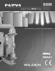
<strong>P2</strong>MOriginal Series METAL <strong>Pump</strong>s<strong>EOM</strong>EngineeringOperation &MaintenanceSimplify your processWIL-10180-E-02Replaces <strong>EOM</strong>-<strong>P2</strong>M 04/05
TABLE OF CONTENTSPAGE #SECTION 1 — CAUTIONS ............................................................................................ 1SECTION 2 — PUMP DESIGNATION SYSTEM ......................................... 2SECTION 3 — HOW IT WORKS (PUMP & AIR SYSTEMS) ............ 3SECTION 4 — DIMENSIONAL DRAWINGSA. <strong>P2</strong> METAL .................................................................................................................... 4B. <strong>P2</strong> METAL SANIFLO FDA ...................................................................................................... 4C. <strong>P2</strong> METAL Bolted ............................................................................................................... 5SECTION 5 — PERFORMANCE CURVESA. <strong>P2</strong> METAL Rubber-Fitted ................................................................................................... 6B. <strong>P2</strong> METAL TPE-Fitted ........................................................................................................ 6C. <strong>P2</strong> METAL PTFE-Fitted ...................................................................................................... 7SECTION 6 — SUCTION LIFT CURVES ........................................................... 7SECTION 7 — INSTALLATION AND OPERATIONA. Installation .......................................................................................................................... 8B. Operation & Maintenance .................................................................................................. 9C. Troubleshooting .................................................................................................................. 10SECTION 8 — DIRECTIONS FOR DISASSEMBLY/REASSEMBLYA. <strong>P2</strong> METAL Wetted Path — Tools Required, Torque Specs, Cautions ............................... 11B. Pro-Flo ® Air Valve/Center Block – Disassembly, Cleaning, Inspection ............................. 13C. Reassembly Hints & Tips ................................................................................................... 15SECTION 9 — EXPLODED VIEW/PARTS LISTINGA. <strong>P2</strong> METAL Rubber/TPE-Fitted ........................................................................................... 16B. <strong>P2</strong> METAL PTFE-Fitted ...................................................................................................... 18SECTION 10 — ELASTOMER OPTIONS ......................................................... 20ClassI &II OzoneNONU.S. Clean Air ActAmendments of 1990DepletingUSESubstances
SECTION 1<strong>P2</strong> METALCAUTIONS – READ FIRST!TEMPERATURE LIMITS:Polypropylene 0°C to 79.4°C 32°F to 175°FAcetal –28.9°C to 65.6°C –20°F to 150°FNeoprene –17.8°C to 93.3°C 0°F to 200°FBuna-N –12.2°C to 82.2°C 10°F to 180°FEPDM –51.1°C to 137.8°C –60°F to 280°FViton ® –40°C to 176.7°C –40°F to 350°FWil-Flex –40°C to 107.2°C –40°F to 2<strong>25</strong>°FPolyurethane –12.2°C to 65.6°C 10°F to 150°FSaniflex –28.9°C to 104.4°C –20°F to 220°FPTFE 4.4°C to 148.9°C 40°F to 300°FCAUTION: When choosing pump materials, be sureto check the temperature limits for all wetted components.Example: Viton ® has a maximum limit of 176.7°C(350°F) but Acetal has a maximum limit of only 65.6°C(150°F).CAUTION: Maximum temperature limits are basedupon mechanical stress only. Certain chemicals willsignificantly reduce maximum safe operating temperatures.Consult engineering guide for chemical compatibilityand temperature limits.CAUTION: Always wear safety glasses when operatingpump. If diaphragm rupture occurs, material beingpumped may be forced out air exhaust.WARNING: Prevention of static sparking — If staticsparking occurs, fire or explosion could result. <strong>Pump</strong>,valves, and containers must be properly grounded whenhandling fla<strong>mm</strong>able fluids and whenever discharge ofstatic electricity is a hazard.CAUTION: Do not exceed 8.6 bar (1<strong>25</strong> psig) air supplypressure.CAUTION: Before any maintenance or repair isattempted, the compressed air line to the pump shouldbe disconnected and all air pressure allowed to bleedfrom pump. Disconnect all intake, discharge and airlines. Drain the pump by turning it upside down andallowing any fluid to flow into a suitable container.CAUTION: Blow out air line for 10 to 20 secondsbefore attaching to pump to make sure all pipe linedebris is clear. Use an in-line air filter. A 5 µ (micron) airfilter is reco<strong>mm</strong>ended.NOTE: Tighten all hardware prior to installation.Fittings may loosen during transportation.NOTE: When installing PTFE diaphragms, it is importantto tighten outer pistons simultaneously (turning inopposite directions) to ensure tight fit.NOTE: Before starting disassembly, mark a line fromeach liquid chamber to its corresponding air chamber.This line will assist in proper alignment during reassembly.CAUTION: Verify the chemical compatibility of theprocess and cleaning fluid to the pump’s componentmaterials in the Chemical Resistance Guide (see E4).CAUTION: Do not over-tighten the air inlet reducerbushing. Too much torque on the reducer may damageeither the reducer bushing or center section. Do notexceed 10.9 N•m (8 ft-lbs).CAUTION: Do not exceed the maximum torquespecification of 13.0 N•m (115 in-lbs) on the liquidchamber to air chamber fasteners on the <strong>P2</strong> Boltedconfiguration.WIL-10180-E-021 WILDEN PUMP & ENGINEERING, LLC
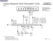
SECTION 2WILDEN PUMP DESIGNATION SYSTEM<strong>P2</strong> /XXXXX/ XXX / XX /XXX / XXXXMODELO-RINGSVALVE SEATVALVE BALLSDIAPHRAGMSAIR VALVECENTER SECTIONWETTED PARTS & OUTER PISTONSPECIALTYCODE(if applicable)MODEL <strong>P2</strong> METAL MATERIAL CODESWETTED PARTS & OUTER PISTONAA = ALUMINUM / ALUMINUMAZ = ALUMINUM / NO PISTONHH = ALLOY C / ALLOY CHZ = ALLOY C / NO PISTONSS = STAINLESS STEEL / STAINLESSSTEELSZ = STAINLESS STEEL /NO PISTONCENTER SECTIONLL = ACETALPP = POLYPROPYLENEAIR VALVEL = ACETALP = POLYPROPYLENESPECIALTY CODES0002 Unpainted special instructions0023 Wing nuts0070 Saniflo FDA0079 Tri-clamp fittings, wing nuts0080 Tri-clamp fittings ONLY0100 Wil-Gard II 110V0102 Wil-Gard II sensor wires ONLY0103 Wil-Gard II 220V0104 Wil-Gard II 110V, spark free0206 PFA coated hardware,Wil-Gard II sensor wires ONLYDIAPHRAGMSBNS = BUNA-N (Red Dot)EPS = EPDM (Blue Dot)FSS = SANIFLEX[Hytrel ® (Cream)]NES = NEOPRENE (Green Dot)PUS = POLYURETHANE (Clear)TEU = PTFE W/EPDMBACK-UP (White)TNL = PTFE W/NEOPRENEBACK-UP O-RING,IPD (White)TSU = PTFE W/SANIFLEX BACK-UP(White)VTS = VITON ® (White Dot)WFS = WIL-FLEX [Santoprene ®(Orange Dot)]XBS = CONDUCTIVE BUNA-N (Two RedDots)VALVE BALLBN = BUNA-N (Red Dot)EP = EPDM (Blue Dot)FS = SANIFLEX[Hytrel ® (Cream)]FV = SANITARY VITON ®(Two White Dots)NE = NEOPRENE (Green Dot)PU = POLYURETHANE (Brown)TF = PTFE (White)VT = VITON ® (White Dot)WF = WIL-FLEX [Santoprene ® (OrangeDot)]VALVE SEATA = ALUMINUMH = ALLOY CS = STAINLESS STEELVALVE SEAT O-RINGBN = BUNA-NEP = EPDMFS = SANIFLEX[Hytrel ® (Cream)]PU = POLYURETHANE (Brown)TF = PTFE (White)WF = WIL-FLEX [Santoprene ® ]0247 Discharge and inlet facing exhaust0<strong>25</strong>0 Discharge facing forward0502 PFA coated hardware0603 PFA coated hardware, Wil-Gard II 110V0608 PFA coated hardware, Wil-Gard II 220V0720 Hybrid bolted0721 Hybrid bolted, BSPT0722 Hybrid bolted, SanifloNOTE: MOST ELASTOMERIC MATERIALS USE COLORED DOTS FOR IDENTIFICATION.Viton is a registered trademarks of DuPont Dow Elastomers.WILDEN PUMP & ENGINEERING, LLC2WIL-10180-E-02
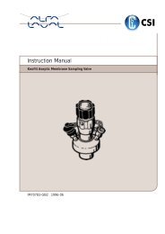
SECTION 3THE WILDEN PUMP — HOW IT WORKSThe Wilden diaphragm pump is an air-operated, positive displacement, self-priming pump. These drawings show the flowpattern through the pump upon its initial stroke. It is assumed the pump has no fluid in it prior to its initial stroke.FIGURE 1 The air valve directs pressurized air tothe back side of diaphragm A. The compressedair is applied directly to the liquid column separatedby elastomeric diaphragms. The diaphragmacts as a separation membrane between thecompressed air and liquid, balancing the load andremoving mechanical stress from the diaphragm.The compressed air moves the diaphragm awayfrom the center section of the pump. The oppositediaphragm is pulled in by the shaft connected tothe pressurized diaphragm. Diaphragm B is on itssuction stroke; air behind the diaphragm has beenforced out to the atmosphere through the exhaustport of the pump. The movement of diaphragm Btoward the center section of the pump creates avacuum within chamber B. Atmospheric pressureforces fluid into the inlet manifold forcing the inletvalve ball off its seat. Liquid is free to move pastthe inlet valve ball and fill the liquid chamber (seeshaded area).FIGURE 2 When the pressurized diaphragm,diaphragm A, reaches the limit of its dischargestroke, the air valve redirects pressurized air tothe back side of diaphragm B. The pressurized airforces diaphragm B away from the center sectionwhile pulling diaphragm A to the center section.Diaphragm B is now on its discharge stroke.Diaphragm B forces the inlet valve ball onto itsseat due to the hydraulic forces developed in theliquid chamber and manifold of the pump. Thesesame hydraulic forces lift the discharge valve balloff its seat, while the opposite discharge valve ballis forced onto its seat, forcing fluid to flow throughthe pump discharge. The movement of diaphragmA toward the center section of the pump creates avacuum within liquid chamber A. Atmospheric pressureforces fluid into the inlet manifold of the pump.The inlet valve ball is forced off its seat allowing thefluid being pumped to fill the liquid chamber.FIGURE 3 At completion of the stroke, the air valveagain redirects air to the back side of diaphragm A,which starts diaphragm B on its exhaust stroke. Asthe pump reaches its original starting point, eachdiaphragm has gone through one exhaust and onedischarge stroke. This constitutes one completepumping cycle. The pump may take several cyclesto completely prime depending on the conditions ofthe application.PRO-FLO ® AIR DISTRIBUTION SYSTEMOPERATION — HOW IT WORKSThe Pro-Flo ® patented air distributionsystem incorporates three moving parts:the air valve spool, the pilot spool, and themain shaft/diaphragm assembly. The heartof the system is the air valve spool and airvalve. The air valve design incorporates anunbalanced spool. The smaller end of thespool is pressurized continuously, while thelarge end is alternately pressurized thenexhausted to move the spool. The spooldirects pressurized air to one air chamberwhile exhausting the other. The air causesthe main shaft/diaphragm assembly toshift to one side — discharging liquid onthat side and pulling liquid in on the otherside. When the shaft reaches the end of itsstroke, the inner piston actuates the pilotspool, which pressurizes and exhausts thelarge end of the air valve spool. The repositioningof the air valve spool routes the airto the other air chamber.WIL-10180-E-023 WILDEN PUMP & ENGINEERING, LLC
SECTION 4ADIMENSIONAL DRAWING<strong>P2</strong> METAL19 <strong>mm</strong> (3/4") FNPT LIQUID DISCHARGE6 <strong>mm</strong>(1/4") FNPTAIR INLET<strong>25</strong> <strong>mm</strong> (1”) FNPT LIQUID INLET13 <strong>mm</strong> (1/2") FNPT AIREXHAUSTDIMENSIONSITEM METRIC (<strong>mm</strong>) STANDARD (inch)A 267 10.5B 36 1.4C 152 6.0D <strong>25</strong>4 10.0E 279 11.0F 28 1.1G 76 3.0H 117 4.6J 152 6.0K 201 7.9L 211 8.3M 173 6.8N 107 4.2P 127 5.0R 33 1.3S 8 0.3SECTION 4BDIMENSIONAL DRAWING<strong>P2</strong> METAL SANIFLO FDA38 <strong>mm</strong> (1-1/2") TRI-CLAMP LIQUID DISCHARGE6 <strong>mm</strong>(1/4") FNPTAIR INLET38 <strong>mm</strong> (1-1/2")TRI-CLAMP LIQUID INLETWILDEN PUMP & ENGINEERING, LLC413 <strong>mm</strong> (1/2")FNPT AIREXHAUSTDIMENSIONSITEM METRIC (<strong>mm</strong>) STANDARD (inch)A 264 10.4B 36 1.4C 157 6.2D <strong>25</strong>7 10.1E <strong>25</strong>4 10.0F 282 11.1G 41 1.6H 76 3.0J 117 4.6K 155 6.1L 203 8.0M 211 8.3N 173 6.8P 107 4.2R 127 5.0S 8 0.3T 43 1.7WIL-10180-E-02
SECTION 4CDIMENSIONAL DRAWING<strong>P2</strong> METAL BOLTED19 <strong>mm</strong> (3/4") FNPT LIQUID DISCHARGE13 <strong>mm</strong>(1/2”)FNPT AIREXHAUST6 <strong>mm</strong>(1/4") FNPTAIR INLET<strong>25</strong> <strong>mm</strong> (1") FNPTLIQUID INLETDIMENSIONSITEM METRIC (<strong>mm</strong>) STANDARD (inch)A 267 10.5B 36 1.4C 152 6.0D <strong>25</strong>4 10.0E 279 11.0F 28 1.1G 76 3.0H 117 4.6J 152 6.0K 229 9.0L 211 8.3M 173 6.8N 107 4.2P 127 5.0R 33 1.3S 8 0.3WIL-10180-E-0<strong>25</strong> WILDEN PUMP & ENGINEERING, LLC
SECTION 5APERFORMANCE CURVES<strong>P2</strong> METAL RUBBER-FITTEDHeight .................................. 279 <strong>mm</strong> (11.0")Width ................................... 267 <strong>mm</strong> (10.5")Depth .................................... 201 <strong>mm</strong> (7.9")Est. Ship Weight .........Aluminum, 12 kg (26 lbs)Stainless Steel, 16 kg (36 lbs)Alloy C, 18 kg (40 lbs)Air Inlet ......................................6 <strong>mm</strong> (1/4")Inlet ............................................ <strong>25</strong> <strong>mm</strong> (1")Outlet ......................................19 <strong>mm</strong> (3/4")Suction Lift ......................... 5.79 m (19' Dry)8.53 m (28' Wet)Displacement perStroke .........................0.34 l (0.091 gal.) 1Max. Flow Rate .................170 lpm (45 gpm)Max. Size Solids .....................3.2 <strong>mm</strong> (1/8")1Displacement per stroke was calculated at 4.8 Bar(70 psig) air inlet pressure against a 2 Bar (30 psig)head pressure.Example: To pump 76 lpm (20 gpm) againsta discharge pressure head of 2.7 bar (40psig) requires 4.1 bar (60 psig) and 22.0Nm 3 /h (13.0 scfm) air consumption. (See doton chart.)Caution: Do not exceed 8.6 bar (1<strong>25</strong> psig) airsupply pressure.[LPM]Flow rates indicated on chart were determined by pumping water.For optimum life and performance, pumps should be specified so that daily operation parameterswill fall in the center of the pump performance curve.SECTION 5BPERFORMANCE CURVES<strong>P2</strong> METAL TPE-FITTEDHeight .................................. 279 <strong>mm</strong> (11.0")Width ................................... 267 <strong>mm</strong> (10.5")Depth .................................... 201 <strong>mm</strong> (7.9")Est. Ship Weight .........Aluminum, 12 kg (26 lbs)Stainless Steel, 16 kg (36 lbs)Alloy C, 18 kg (40 lbs)Air Inlet ......................................6 <strong>mm</strong> (1/4")Inlet ............................................ <strong>25</strong> <strong>mm</strong> (1")Outlet ......................................19 <strong>mm</strong> (3/4")Suction Lift ......................... 5.48 m (18' Dry)8.53 m (28' Wet)Displacement perStroke .........................0.34 l (0.091 gal.) 1Max. Flow Rate .................170 lpm (45 gpm)Max. Size Solids .....................3.2 <strong>mm</strong> (1/8")1Displacement per stroke was calculated at 4.8 bar(70 psig) air inlet pressure against a 2 bar (30 psig)head pressure.Example: To pump 61 lpm (16 gpm) againsta discharge pressure head of 2.7 bar(40 psig) requires 4 bar (60 psig) and 17Nm 3 /h (10 scfm) air consumption. (See doton chart.)Caution: Do not exceed 8.6 bar (1<strong>25</strong> psig) airsupply pressure.[LPM]Flow rates indicated on chart were determined by pumping water.For optimum life and performance, pumps should be specified so that daily operation parameterswill fall in the center of the pump performance curve.WILDEN PUMP & ENGINEERING, LLC6WIL-10180-E-02
SECTION 5CPERFORMANCE CURVES<strong>P2</strong> METAL PTFE-FITTEDHeight .................................. 279 <strong>mm</strong> (11.0")Width ................................... 267 <strong>mm</strong> (10.5")Depth .................................... 201 <strong>mm</strong> (7.9")Est. Ship Weight .........Aluminum, 12 kg (26 lbs)Stainless Steel, 16 kg (36 lbs)Alloy C, 18 kg (40 lbs)Air Inlet ......................................6 <strong>mm</strong> (1/4")Inlet ............................................ <strong>25</strong> <strong>mm</strong> (1")Outlet ......................................19 <strong>mm</strong> (3/4")Suction Lift ......................... 3.04 m (10' Dry)8.53 m (28' Wet)Displacement perStroke .........................0.23 l (0.061 gal.) 1Max. Flow Rate .................163 lpm (43 gpm)Max. Size Solids .....................3.2 <strong>mm</strong> (1/8")1Displacement per stroke was calculated at 4.8 bar(70 psig) air inlet pressure against a 2 bar (30 psig)head pressure.Example: To pump 87 lpm (23 gpm) againsta discharge pressure head of 2.7 bar (40psig) requires 5.5 bar (80 psig) and 55.8Nm 3 /h (33 scfm) air consumption. (See doton chart.)Caution: Do not exceed 8.6 bar (1<strong>25</strong> psig) airsupply pressure.[LPM]SECTION 6SUCTION LIFT CURVESFlow rates indicated on chart were determined by pumping water.For optimum life and performance, pumps should be specified so that daily operation parameterswill fall in the center of the pump performance curve.PTFE Diaphragms[0.7] [1.4] [2.0] [2.7] [3.4] [4.1] [4.8] [5.5] [6.2] [6.9]Suction lift curves are calibrated for pumps operating at305 m (1,000') above sea level. This chart is meant to be aguide only. There are many variables which can affect yourpump’s operating characteristics. The number of intake anddischarge elbows, viscosity of pumping fluid, elevation (atmosphericpressure) and pipe friction loss all affect the amountof suction lift your pump will attain.WIL-10180-E-027 WILDEN PUMP & ENGINEERING, LLC
SECTION 7AINSTALLATIONThe <strong>P2</strong> Pro-Flo ® model has a <strong>25</strong> <strong>mm</strong> (1") inlet and 19 <strong>mm</strong>(3/4") outlet and is designed for flows to 170 lpm (45 gpm).Refer to Section 5 for performance characteristics. The <strong>P2</strong><strong>Metal</strong> pump is manufactured with wetted parts of Aluminum,316 Stainless Steel, and Alloy C. The <strong>P2</strong> is available witha polypropylene or acetal air valve and center section. Avariety of diaphragms, valve balls, valve seats and o-ringsare available to satisfy temperature, chemical compatibility,abrasion and flex concerns.The suction pipe size should be at least <strong>25</strong> <strong>mm</strong> (1") diameteror larger if highly viscous material is being pumped.The suction hose must be non-collapsible, reinforced typeas the <strong>P2</strong> is capable of pulling a high vacuum. Dischargepiping should be at least <strong>25</strong> <strong>mm</strong> (1"); larger diameter canbe used to reduce friction losses. It is critical that all fittingsand connections are airtight or a reduction or loss of pumpsuction capability will result.INSTALLATION: Months of careful planning, study, andselection efforts can result in unsatisfactory pump performanceif installation details are left to chance.Premature failure and long term dissatisfaction can beavoided if reasonable care is exercised throughout theinstallation process.LOCATION: Noise, safety, and other logistical factors usuallydictate where equipment will be situated on the productionfloor. Multiple installations with conflicting requirements canresult in congestion of utility areas, leaving few choices foradditional pumps.Within the framework of these and other existing conditions,every pump should be located in such a way that five key factorsare balanced against each other to maximum advantage.ACCESS: First of all, the location should be accessible. Ifit’s easy to reach the pump, maintenance personnel willhave an easier time carrying out routine inspections andadjustments. Should major repairs become necessary, easeof access can play a key role in speeding the repair processand reducing total downtime.AIR SUPPLY: Every pump location should have an air linelarge enough to supply the volume of air necessary toachieve the desired pumping rate (see Section 5). Use airpressure up to a maximum of 8.6 bar (1<strong>25</strong> psig) dependingon pumping requirements.For best results, the pumps should use a 5 micron air filter,needle valve and regulator. The use of an air filter before thepump will ensure that the majority of any pipeline contaminantswill be eliminated.When operation is controlled by a solenoid valve in the air line,three-way valves should be used. This valve allows trapped airbetween the valve and the pump to bleed off which improvespump performance. <strong>Pump</strong>ing volume can be determined bycounting the number of strokes per minute and then multiplyingthe figure by the displacement per stroke.MUFFLER: Sound levels are reduced below OSHA specificationsusing the standard Wilden muffler. Other mufflerscan be used to further reduce sound levels, but they usuallyreduce pump performance.WILDEN PUMP & ENGINEERING, LLCELEVATION: Selecting a site that is well within the pump’sdynamic lift capability will assure that loss-of-prime troubleswill be eliminated. In addition, pump efficiency can beadversely affected if proper attention is not given to sitelocation.PIPING: Final determination of the pump site should notbe made until the piping problems of each possible locationhave been evaluated. The impact of current and futureinstallations should be considered ahead of time to makesure that inadvertent restrictions are not created for anyremaining sites.The best choice possible will be a site involving the shortestand straightest hook-up of suction and discharge piping.Unnecessary elbows, bends, and fittings should be avoided.Pipe sizes should be selected so as to keep friction losseswithin practical limits. All piping should be supported independentlyof the pump. In addition, the piping should bealigned so as to avoid placing stress on the pump fittings.Flexible hose can be installed to aid in absorbing the forcescreated by the natural reciprocating action of the pump. Ifthe pump is to be bolted down to a solid location, a mountingpad placed between the pump and the foundation willassist in minimizing pump vibration. Flexible connectionsbetween the pump and rigid piping will also assist in minimizingpump vibration. If quick-closing valves are installedat any point in the discharge system, or if pulsation withina system becomes a problem, a surge suppressor shouldbe installed to protect the pump, piping and gauges fromsurges and water ha<strong>mm</strong>er.If the pump is to be used in a self-priming application, besure that all connections are airtight and that the suction liftis within the model’s ability. Note: Materials of constructionand elastomer material have an effect on suction lift parameters.Please refer to Section 6 for specifics.The <strong>P2</strong> can be installed in submersible applications onlywhen both the wetted and non-wetted portions are compatiblewith the material being pumped. If the pump is tobe used in a submersible application, a hose should beattached to the pump’s air and pilot spool exhaust portsand piped above the liquid level. The exhaust area for thepilot spool is designed to be tapped for a 3.2 <strong>mm</strong> (1/8")NPT fitting.When pumps are installed in applications involving floodedsuction or suction head pressures, a gate valve should beinstalled in the suction line to permit closing of the line forpump service.<strong>Pump</strong>s in service with a positive suction head are mostefficient when inlet pressure is limited to 0.5–0.7 bar (7–10psig). Premature diaphragm failure may occur if positivesuction is 0.7 bar (10 psig) and higher.THE MODEL <strong>P2</strong> WILL PASS 3.2 MM (1/8") SOLIDS. WHEN-EVER THE POSSIBILITY EXISTS THAT LARGER SOLIDOBJECTS MAY BE SUCKED INTO THE PUMP, A STRAINERSHOULD BE USED ON THE SUCTION LINE.CAUTION: DO NOT EXCEED 8.6 BAR (1<strong>25</strong> PSIG) AIRSUPPLY PRESSURE.8WIL-10180-E-02
SUGGESTED INSTALLATIONCOMBINATIONFILTER ®ULATORFLEXIBLECONNECTIONGAUGE(OPTIONAL)SHUT OFFVALVEAIRSHUTOFFVALVENEEDLEVALVEPIPE CONNECTION(STYLE OPTIONAL)®EQUALIZERSURGE DAMPENER(OPTIONAL)DISCHARGEMUFFLERSUCTIONTo stop the pump from operating in an emergency situation, simplyclose the shut-off valve (user supplied) installed in the air supply line. Aproperly functioning valve will stop the air supply to the pump, thereforestopping output. This shut-off valve should be located far enoughaway from the pumping equipment such that it can be reached safelyin an emergency situation.NOTE: In the event of a power failure, the shutoff valve should be closed,if the restarting of the pump is not desirable once power is regained.SECTION 7BSUGGESTED OPERATION ANDMAINTENANCE INSTRUCTIONSOPERATION: <strong>Pump</strong> discharge rate can be controlled bylimiting the volume and/or pressure of the air supply to thepump (preferred method). An air regulator is used to regulateair pressure. A needle valve is used to regulate volume. <strong>Pump</strong>discharge rate can also be controlled by throttling the pumpdischarge by partially closing a valve in the discharge line ofthe pump. This action increases friction loss which reducesflow rate. This is useful when the need exists to control thepump from a remote location. When the pump dischargepressure equals or exceeds the air supply pressure, thepump will stop; no bypass or pressure relief valve is needed,and pump damage will not occur. The pump has reached a“deadhead” situation and can be restarted by reducing thefluid discharge pressure or increasing the air inlet pressure.The Wilden <strong>P2</strong> pump runs solely on compressed air and doesnot generate heat, therefore your process fluid temperaturewill not be affected.RECORDS: When service is required, a record should bemade of all necessary repairs and replacements. Over aperiod of time, such records can become a valuable tool forpredicting and preventing future maintenance problems andunscheduled downtime. In addition, accurate records makeit possible to identify pumps that are poorly suited to theirapplications.MAINTENANCE AND INSPECTIONS: Since each applicationis unique, maintenance schedules may be differentfor every pump. Frequency of use, line pressure, viscosityand abrasiveness of process fluid all affect the parts lifeof a Wilden pump. Periodic inspections have been foundto offer the best means for preventing unscheduled pumpdowntime. Personnel familiar with the pump’s constructionand service should be informed of any abnormalities that aredetected during operation.WIL-10180-E-029 WILDEN PUMP & ENGINEERING, LLC
SECTION 7CTROUBLESHOOTING<strong>Pump</strong> will not run or runs slowly.1. Ensure that the air inlet pressure is at least 0.4 bar (5 psig)above startup pressure and that the differential pressure(the difference between air inlet and liquid dischargepressures) is not less than 0.7 bar (10 psig).2. Check air inlet filter for debris (see reco<strong>mm</strong>endedinstallation).3. Check for extreme air leakage (blow by) which wouldindicate worn seals/bores in the air valve, pilot spool,main shaft.4. Disassemble pump and check for obstructions in theair passageways or objects which would obstruct themovement of internal parts.5. Check for sticking ball check valves. If material beingpumped is not compatible with pump elastomers, swellingmay occur. Replace ball check valves and seals withproper elastomers. Also, as the check valve balls wearout, they become smaller and can become stuck in theseats. In this case, replace balls and seats.6. Check for broken inner piston which will cause the airvalve spool to be unable to shift.7. Remove plug from pilot spool exhaust.<strong>Pump</strong> runs but little or no product flows.1. Check for pump cavitation; slow pump speed down toallow thick material to flow into liquid chambers.2. Verify that vacuum required to lift liquid is not greater thanthe vapor pressure of the material being pumped (cavitation).3. Check for sticking ball check valves. If material beingpumped is not compatible with pump elastomers, swellingmay occur. Replace ball check valves and seals withproper elastomers. Also, as the check valve balls wearout, they become smaller and can become stuck in theseats. In this case, replace balls and seats.<strong>Pump</strong> air valve freezes.1. Check for excessive moisture in compressed air. Eitherinstall a dryer or hot air generator for compressed air.Alternatively, a coalescing filter may be used to removethe water from the compressed air in some applications.Air bubbles in pump discharge.1. Check for ruptured diaphragm.2. Check tightness of outer pistons (refer to Section 8C).3. Check tightness of clamp bands and integrity of o-ringsand seals, especially at intake manifold.4. Ensure pipe connections are airtight.Product comes out air exhaust.1. Check for diaphragm rupture.2. Check tightness of outer pistons to shaft.WILDEN PUMP & ENGINEERING, LLC10WIL-10180-E-02
SECTION 8A<strong>P2</strong> METALDIRECTIONS FOR DISASSEMBLY/REASSEMBLYCAUTION: Before any maintenance or repair is attempted,the compressed air line to the pump should be disconnectedand all air pressure allowed to bleed from the pump. Disconnectall intake, discharge, and air lines. Drain the pump byturning it upside down and allowing any fluid to flow intoa suitable container. Be aware of any hazardous effects ofcontact with your process fluid.The Wilden model <strong>P2</strong> has a <strong>25</strong> <strong>mm</strong> (1") inlet and 19 <strong>mm</strong>(3/4") outlet and is designed for flows up to 170 lpm(45 gpm). The single-piece center section, consisting of centerblock and air chambers, is molded of acetal or Polypropylene.All o-rings used in the pump are of a special material and shorehardness that should only be replaced with factory-suppliedparts.TOOLS REQUIRED:Adjustable Wrench1/2" Box End Wrench9/16" Box End Wrench3/4" Box End Wrench1/4" Hex Head WrenchVise equipped with soft jaws (such as plywood, plasticor other suitable material)NOTE: The model used for these instructions incorporatesrubber diaphragms, balls, and seats. Models with PTFEdiaphragms, balls and seats are the same except wherenoted.DISASSEMBLY:Figure 1Step 1.Before starting disassembly, mark a line from each liquidchamber to its corresponding air chamber. This line willassist in proper alignment during reassembly.Step 2. Figure 2Utilizing the 9/16" box wrench, start byremoving the four long carriage boltsthat secure the top and bottom manifoldsto the center section.Step 3. Figure 3Remove the top manifold and lift thecenter section off the inlet manifold.Step 4. Figure 4Remove the discharge valve balls,seats and o-rings from the dischargemanifold and inspect for nicks,gouges, chemical attack or abrasivewear. Replace worn parts with genuineWilden parts for reliable performance.PTFE o-rings should be replaced whenreassembled.WIL-10180-E-0211 WILDEN PUMP & ENGINEERING, LLC
Step 5. Figure 5With one 1/2" box wrench (stainlesssteel or Alloy C configuration ) or 1/4"hex head wrench (aluminum configuration),remove the liquid chamber from thecenter section. BOLTED CONFIGURA-TION ONLY. Stainless steel configurationshown above.Step 6. Figure 6Inspect the valve seat, valve seato-ring, and valve ball from intake manifold.Check for nicks, gouges, chemicalattack or abrasive wear. Replace wornparts with genuine Wilden parts for reliableperformance. PTFE o-rings shouldbe replaced when reassembled.Step 7. Figure 7With the 3/4" box wrench or by rotatingthe diaphragm by hand, remove thediaphragm assembly.Step 8. Figure 8NOTE: Due to varying torque values, oneof the following two situations may occur:1) The outer piston, diaphragm and innerpiston remain attached to the shaft andthe entire assembly can be removed fromthe center section.Step 9. Figure 92) The outer piston, diaphragm, innerpiston, and disc spring separate fromthe shaft which remains connected tothe opposite side diaphragm assembly.PTFE-fitted pumps come standardwith back-up diaphragms (not shown).Step 10. Figure 10To remove the diaphragm assembly fromthe shaft, secure shaft with soft jaws (avise fitted with plywood or other suitablematerial) to ensure shaft is not nicked,scratched, or gouged. Using a wrench,remove diaphragm assembly from shaft.Inspect all parts for wear and replacewith genuine Wilden parts if necessary.WILDEN PUMP & ENGINEERING, LLC12WIL-10180-E-02
SECTION 8BPRO-FLO ® AIR VALVE/CENTER SECTIONDISASSEMBLY, CLEANING, INSPECTIONAIR VALVE DISASSEMBLY:CAUTION: Before any maintenance or repair is attempted,the compressed air line to the pump should be disconnectedand all air pressure allowed to bleed from thepump. Disconnect all intake, discharge, and air lines. Drainthe pump by turning it upside down and allowing any fluidto flow into a suitable container. Be aware of hazardouseffects of contact with your process fluid.The Wilden <strong>Metal</strong> <strong>P2</strong> utilizes a revolutionary Pro-Flo ® airdistribution system. A 6 <strong>mm</strong> (1/4") air inlet connects theair supply to the center section. Proprietary compositeseals reduce the co efficient of friction and allow the <strong>P2</strong> torun lube-free. Constructed of acetal or polypropylene airvalve with a polypropylene center section, the Pro-Flo ® airdistribution system is designed to perform in on/off, nonfreezing,non-stalling, tough duty applications.TOOLS REQUIRED:3/16" Hex Head WrenchSnap Ring PliersO-Ring PickStep 1. Figure 1Loosen the air valve bolts utilizing a 3/16" hex head wrench.Step 2. Figure 2Remove muffler plate and air valvebolts from air valve assembly exposingmuffler gasket for inspection. Replace ifnecessary.Step 3. Figure 3Lift away air valve assembly and removeair valve gasket for inspection. Replaceif necessary.Step 4. Figure 4Remove air valve end cap to expose airvalve spool by simply lifting up on endcap once air valve bolts are removed.WIL-10180-E-0213 WILDEN PUMP & ENGINEERING, LLC
Step 5. Figure 5Remove air valve spool from air valve body by threadingone air valve bolt into the end of the spool and gently slidingthe spool out of the air valve body. Inspect seals for signs ofwear and replace entire assembly if necessary. Use cautionwhen handling air valve spool to prevent damaging seals.NOTE: Seals should not be removed from assembly.Seals are not sold separately.Step 6. Figure 6Remove pilot spool sleeve retaining snap ring on both sidesof center section with snap ring pliers.Step 7. Figure 7Remove pilot spool sleeve from centersection.Step 8. Figure 8With o-ring pick, gently remove pilotspool retaining o-ring from the end ofthe pilot spool opposite the marked end.Replace if necessary. Gently remove pilotspool from sleeve and inspect spool andseals for nicks, gouges or other signs ofwear. Replace pilot sleeve assembly orouter sleeve o-rings if necessary.NOTE: Seals should not be removedfrom pilot spool.Seals are not sold separately.Step 9. Figure 9Check center section Glyd rings forsigns of wear. If necessary, removeGlyd rings with o-ring pick andreplace.WILDEN PUMP & ENGINEERING, LLC14WIL-10180-E-02
SECTION 8CREASSEMBLY HINTS & TIPSASSEMBLY:Upon performing applicable maintenance to the air distributionsystem, the pump can now be reassembled. Please refer tothe disassembly instructions for photos and parts placement.To reassemble the pump, follow the disassembly instructions inreverse order. The air distribution system needs to be assembledfirst, then the diaphragms and finally the wetted path.Please find the applicable torque specifications on this page.The following tips will assist in the assembly process.• Clean the inside of the center section shaft bore to ensureno damage is done to new seals.• Stainless bolts should be lubed to reduce the possibility ofseizing during tightening.• Be sure to tighten outer pistons simultaneously on PTFEfittedpumps to ensure proper torque values.• Place one liquid chamber on its side and align centersection with chamber using alignment marks made duringdisassembly. Push down on diaphragm assembly untildiaphragm is inverted. Place opposite liquid chamber oncenter section and align.• Position valve balls, seats, and o-rings in discharge manifold.Place vertical bolt through discharge manifold withthreads pointing up. Install washer and start threads of bolt(about 1-1/2 turns).• Place center section and liquid chambers on intakemanifold.• Position discharge manifold and bolt assembly onliquid chambers. Ensure proper alignment of matingsurfaces between liquid chambers and manifolds beforetightening bolts.• Apply a small amount of Loctite 242 to the shaft intervalthreads before the diaphragm assembly.• Concave side of disc spring in diaphragm assembly facestoward inner piston.MAXIMUM TORQUE SPECIFICATIONSDescription of Part<strong>Metal</strong> <strong>Pump</strong>sAir Valve, Pro-Flo ®3.1 N•m (27 in-lbs)Air Inlet, Reducer Bushing10.9 N•m (8 ft-lbs)Outer Piston, Rubber and PTFE-Fitted40.7 N•m (30 ft-lbs)Vertical Bolts31.1 N•m (23 ft-lbs)Vertical Bolts, Bolted <strong>Metal</strong> Only13.0 N•m (115 in-lbs)*Liquid Chamber /Air Chamber13.0 N•m (115 in-lbs)*For bolted liquid chamber to bolted center section configuration only.WIL-10180-E-0215 WILDEN PUMP & ENGINEERING, LLC
SECTION 9AEXPLODED VIEW/PARTS LISTING<strong>P2</strong>METALRUBBER/TPE-FITTED<strong>P2</strong> BoltedWILDEN PUMP & ENGINEERING, LLC16WIL-10180-E-02
<strong>P2</strong> METAL RUBBER/TPE-FITTEDPolypropylene Center SectionAcetal Center SectionItem Part DescriptionQtyPer<strong>Pump</strong><strong>P2</strong>/AAPPPP/N<strong>P2</strong>/SSPPPP/N<strong>P2</strong>/HHPPPP/N<strong>P2</strong>/SSPPP/0070P/N <strong>P2</strong>/AALLL P/N <strong>P2</strong>/SSLLL P/N <strong>P2</strong>/ HHLLL P/N<strong>P2</strong>/SSLLL/0070P/N1 Pro-Flo ® Air Valve Assembly 1 1 01-2010-20 01-2010-20 01-2010-20 01-2010-20 01-2010-13 01-2010-13 01-2010-13 01-2010-132 End Cap 1 01-2332-20 01-2332-20 01-2332-20 01-2332-20 01-2332-13 01-2332-13 01-2332-13 01-2332-133 O-Ring, End Cap 1 01-2395-52 01-2395-52 01-2395-52 01-2395-52 01-2395-52 01-2395-52 01-2395-52 01-2395-524 Gasket, Air Valve 1 01-2615-52 01-2615-52 01-2615-52 01-2615-52 01-2615-52 01-2615-52 01-2615-52 01-2615-5<strong>25</strong> Screw, HSHC, Air Valve 1⁄4"-20 4 01-6001-03 01-6001-03 01-6001-03 01-6001-03 01-6001-03 01-6001-03 01-6001-03 01-6001-036 Nut, Hex, 1⁄4"-20 4 04-6400-03 04-6400-03 04-6400-03 04-6400-03 04-6400-03 04-6400-03 04-6400-03 04-6400-037 Center Section 1 02-3145-20 02-3145-20 02-3145-20 02-3145-20 02-3145-13 02-3145-13 02-3145-13 02-3145-138 Bushing, Reducer 1 01-6950-20 01-6950-20 01-6950-20 01-6950-20 01-6950-13 01-6950-13 01-6950-13 01-6950-139 Removable Pilot Sleeve Assembly 1 02-3880-99 02-3880-99 02-3880-99 02-3880-99 02-3880-99 02-3880-99 02-3880-99 02-3880-9910 Glyd Ring II 2 02-3210-55-2<strong>25</strong> 02-3210-55-2<strong>25</strong> 02-3210-55-2<strong>25</strong> 02-3210-55-2<strong>25</strong> 02-3210-55-2<strong>25</strong> 02-3210-55-2<strong>25</strong> 02-3210-55-2<strong>25</strong> 02-3210-55-2<strong>25</strong>11 Retaining Ring 2 00-2650-03 00-2650-03 00-2650-03 00-2650-03 00-2650-03 00-2650-03 00-2650-03 00-2650-0312 Muffler Plate 1 01-3181-20 01-3181-20 01-3181-20 01-3181-20 01-3181-13 01-3181-13 01-3181-13 01-3181-1313 Gasket, Muffler Plate 1 01-3505-52 01-3505-52 01-3505-52 01-3505-52 01-3505-52 01-3505-52 01-3505-52 01-3505-5214 Muffler 1 02-3510-99 02-3510-99 02-3510-99 02-3510-99 02-3510-99 02-3510-99 02-3510-99 02-3510-9915 Shaft, Pro-Flo ® 1 02-3810-03 02-3810-03 02-3810-03 02-3810-03 02-3810-03 02-3810-03 02-3810-03 02-3810-0316 Disc Spring (Belleville Washer) 2 02-6802-08 02-6802-08 02-6802-08 02-6802-08 02-6802-08 02-6802-08 02-6802-08 02-6802-0817 Inner Piston 2 02-3701-01 02-3701-01 02-3701-01 02-3701-01 02-3701-01 02-3701-01 02-3701-01 02-3701-0118 Outer Piston 2 02-4550-01 02-4550-03 02-4550-04 02-4600-03 02-4550-01 02-4550-03 02-4550-04 02-4600-0319 Liquid Chamber 2 02-5000-01 02-5000-03 02-5000-04 02-5000-03 02-5000-01 02-5000-03 02-5000-04 02-5000-0320 Inlet Manifold 1 02-5080-01 02-5080-03 02-5080-04 02-5080-03-70 02-5080-01 02-5080-03 02-5080-04 02-5085-03-7021 Discharge Manifold 1 02-5020-01 02-5020-03 02-5020-04 02-5020-03-70 02-5020-01 02-5020-03 02-5020-04 02-50<strong>25</strong>-03-7022 Screw, SHCS (Chamber Bolt) 4 02-6080-08 02-6080-03 02-6080-03 02-6080-03 02-6080-08 02-6080-03 02-6080-03 02-6080-0323 Vertical Bolt Washer 4 15-6720-08 02-6730-03 02-6730-03 08-6720-07-70 15-6720-08 02-6730-03 02-6730-03 08-6720-07-7024 Vertical Bolt Nut 4 02-6430-08 02-6430-03 02-6430-03 02-6680-03-70 02-6430-08 02-6430-03 02-6430-03 02-6680-03-70<strong>25</strong> Diaphragm 2 * * * 02-1010-56 * * * 02-1010-5626 Valve Ball 4 * * * 02-1080-56 * * * 02-1080-5627 Valve Seat 4 * * * 02-1120-03 * * * 02-1120-0328 Valve Seat O-Ring 4 * * * 02-1200-56 * * * 02-1200-5629 Shaft Stud 2 N/R 02-6150-08 02-6150-08 02-6150-08 N/R 02-6150-08 02-6150-08 02-6150-08<strong>P2</strong> Bolted30 Assy., Center Section, <strong>P2</strong> 1 02-3142-20 02-3142-20 02-3142-20 02-3142-2031 Liquid Chamber, Hybrid 2 02-5005-01 02-5005-03 02-5005-04 02-5005-0332 Screw, Liquid Chamber 16 95-6011-08 08-6180-03-42 08-6180-03-42 08-6180-03-4233 Washer, Flat, .344 x .688 x .065 16 N/R 02-6731-03 02-6731-03 02-6731-031Air Valve Assembly includes items 2 and 3.*Refer to corresponding elastomer chart in Section 10.NOTE: Item #6 is not required for bolted version.Item numbers 30-33 for <strong>P2</strong> Bolted configuration.0070 Specialty Code = Saniflo FDA0720 Specialty Code = Hybrid0721 Specialty Code = Hybrid BSP0722 Specialty Code = Hybrid Saniflo (Not available with aluminum wetted components)All boldface items are primary wear parts.WIL-10180-E-0217 WILDEN PUMP & ENGINEERING, LLC
SECTION 9BEXPLODED VIEW/PARTS LISTING<strong>P2</strong>METALPTFE-FITTED31323433<strong>P2</strong> BoltedWILDEN PUMP & ENGINEERING, LLC18WIL-10180-E-02
<strong>P2</strong> METAL PTFE-FITTEDPolypropylene Center SectionAcetal Center SectionItem Part DescriptionQty.Per<strong>Pump</strong><strong>P2</strong>/AAPPPP/N<strong>P2</strong>/SSPPPP/N<strong>P2</strong>/HHPPPP/N<strong>P2</strong>/SSPPP/0070P/N<strong>P2</strong>/AALLLP/N<strong>P2</strong>/SSLLLP/N<strong>P2</strong>/HHLLLP/N<strong>P2</strong>/SSLLL/0070P/N1 Pro-Flo ® Air Valve Assembly 1 1 01-2010-20 01-2010-20 01-2010-20 01-2010-20 01-2010-13 01-2010-13 01-2010-13 01-2010-132 End Cap 1 01-2332-20 01-2332-20 01-2332-20 01-2332-20 01-2332-13 01-2332-13 01-2332-13 01-2332-133 O-Ring, End Cap 1 01-2395-52 01-2395-52 01-2395-52 01-2395-52 01-2395-52 01-2395-52 01-2395-52 01-2395-524 Gasket, Air Valve 1 01-2615-52 01-2615-52 01-2615-52 01-2615-52 01-2615-52 01-2615-52 01-2615-52 01-2615-5<strong>25</strong> Screw, HHC, Air Valve 1⁄4"-20 4 01-6001-03 01-6001-03 01-6001-03 01-6001-03 01-6001-03 01-6001-03 01-6001-03 01-6001-036 Nut, Hex, 1⁄4"-20 4 04-6400-03 04-6400-03 04-6400-03 04-6400-03 04-6400-03 04-6400-03 04-6400-03 04-6400-037 Center Section Assembly 1 02-3145-20 02-3145-20 02-3145-20 02-3145-20 02-3145-13 02-3145-13 02-3145-13 02-3145-138 Bushing, Reducer 1 01-6950-20 01-6950-20 01-6950-20 01-6950-20 01-6950-13 01-6950-13 01-6950-13 01-6950-139 Removable Pilot Sleeve Assembly 1 02-3880-99 02-3880-99 02-3880-99 02-3880-99 02-3880-99 02-3880-99 02-3880-99 02-3880-9910 Glyd Ring II 2 02-3210-55-2<strong>25</strong> 02-3210-55-2<strong>25</strong> 02-3210-55-2<strong>25</strong> 02-3210-55-2<strong>25</strong> 02-3210-55-2<strong>25</strong> 02-3210-55-2<strong>25</strong> 02-3210-55-2<strong>25</strong> 02-3210-55-2<strong>25</strong>11 Retaining Ring 2 00-2650-03 00-2650-03 00-2650-03 00-2650-03 00-2650-03 00-2650-03 00-2650-03 00-2650-0312 Muffler Plate 1 01-3181-20 01-3181-20 01-3181-20 01-3181-20 01-3181-13 01-3181-13 01-3181-13 01-3181-1313 Gasket, Muffler Plate 1 01-3505-52 01-3505-52 01-3505-52 01-3505-52 01-3505-52 01-3505-52 01-3505-52 01-3505-5214 Muffler 1 02-3510-99 02-3510-99 02-3510-99 02-3510-99 02-3510-99 02-3510-99 02-3510-99 02-3510-9915 Shaft, Pro-Flo ® 1 02-3840-03 02-3840-03 02-3840-03 02-3840-03 02-3840-03 02-3840-03 02-3840-03 02-3840-0316 Disc Spring (Belleville Washer) 2 02-6802-08 02-6802-08 02-6802-08 02-6802-08 02-6802-08 02-6802-08 02-6802-08 02-6802-0817 Inner Piston 2 02-3751-01 02-3751-01 02-3751-01 02-3751-01 02-3751-01 02-3751-01 02-3751-01 02-3751-0118 Outer Piston 2 02-4600-01 02-4600-03 02-4600-04 02-4600-03 02-4600-01 02-4600-03 02-4600-04 02-4600-0319 Liquid Chamber 2 02-5000-01 02-5000-03 02-5000-04 02-5000-03 02-5000-01 02-5000-03 02-5000-04 02-5000-0320 Inlet Manifold 1 02-5080-01 02-5080-03 02-5080-04 02-5080-03-70 02-5080-01 02-5080-03 02-5080-04 02-5085-03-7021 Discharge Manifold 1 02-5020-01 02-5020-03 02-5020-04 02-5020-03-70 02-5020-01 02-5020-03 02-5020-04 02-50<strong>25</strong>-03-7022 Screw, SHCS (Chamber Bolt) 4 02-6080-08 02-6080-03 02-5080-03 02-6080-03 02-6080-08 02-6080-03 02-5080-03 02-6080-0323 Vertical Bolt Washer 4 15-6720-08 02-6730-03 02-6730-03 08-6720-07-70 15-6720-08 02-6730-03 02-6730-03 08-6720-07-7024 Vertical Bolt Nut 4 02-6430-08 02-6430-03 02-6430-03 02-6680-03-70 02-6430-08 02-6430-03 02-6430-03 02-6680-03-70<strong>25</strong> Diaphragm 2 02-1010-55 02-1010-55 02-1010-55 02-1010-56 02-1010-55 02-1010-55 02-1010-55 02-1010-5626 Backup Diaphragm 2 02-1060-56 02-1060-56 02-1060-56 02-1060-56 02-1060-56 02-1060-56 02-1060-56 02-1060-5627 Valve Ball 4 02-1080-55 02-1080-55 02-1080-55 02-1080-56 02-1080-55 02-1080-55 02-1080-55 02-1080-5628 Valve Seat 4 02-1120-01 02-1120-03 02-1120-04 02-1120-03 02-1120-01 02-1120-03 02-1120-04 02-1120-0329 Valve Seat O-Ring 4 02-1200-55 02-1200-55 02-1200-55 02-1200-56 02-1200-55 02-1200-55 02-1200-55 02-1200-56<strong>P2</strong> Bolted31 Assy., Center Section, <strong>P2</strong> Hybrid 1 02-3142-20 02-3142-20 02-3142-20 02-3142-2032 Liquid Chamber, Hybrid 2 02-5005-01 02-5005-03 02-5005-04 02-5005-0333 Screw, SHCS, 5/16"-18 x 1" 16 95-6011-08 08-6180-03-42 08-6180-03-42 08-6180-03-4234 Washer, Flat, .344 x .688 x .065 16 N/R 02-6731-03 02-6731-03 02-6731-031Air Valve Assembly includes items 2 and 3.NOTE: Item #6 is not required for bolted version.Item numbers 30-33 for <strong>P2</strong> <strong>Metal</strong> Bolted configuration.*Refer to corresponding elastomer chart in Section 10.0070 Specialty Code = Saniflo FDA0720 Specialty Code = Hybrid0721 Specialty Code = Hybrid BSP0722 Specialty Code = Hybrid Saniflo (Not available with aluminum wetted components)All boldface items are primary wear parts.WIL-10180-E-0219 WILDEN PUMP & ENGINEERING, LLC
SECTION 10ELASTOMER OPTIONS<strong>P2</strong> <strong>Metal</strong> <strong>Pump</strong>sMATERIALDIAPHRAGMP/NVALVE BALLP/NVALVE SEATP/NVALVE SEATO-RING*P/NPolyurethane 02-1010-50 02-1080-50 N/A 02-1200-50Buna-N 02-1010-52 02-1080-52 N/A 02-1200-52Neoprene 02-1010-51 02-1080-51 N/A N/AEPDM 02-1010-54 02-1080-54 N/A 02-1200-54Viton® 02-1010-53 02-1080-53 N/A N/AWil-Flex 02-1010-58 02-1080-58 N/A 02-1200-58Saniflex 02-1010-56 02-1080-56 N/A 02-1200-56PTFE 02-1010-55 02-1080-55 N/A 02-1200-55Stainless Steel N/A N/A 02-1120-03 N/AAluminum N/A N/A 02-1120-01 N/AAlloy C N/A N/A 02-1120-04 N/AWILDEN PUMP & ENGINEERING, LLC20WIL-10180-E-02
WARRANTYEach and every product manufactured by Wilden <strong>Pump</strong> and Engineering, LLC is built to meet the higheststandards of quality. Every pump is functionally tested to insure integrity of operation.Wilden <strong>Pump</strong> and Engineering, LLC warrants that pumps, accessories and parts manufactured or supplied byit to be free from defects in material and workmanship for a period of five (5) years from date of installation orsix (6) years from date of manufacture, whichever comes first. Failure due to normal wear, misapplication, orabuse is, of course, excluded from this warranty.Since the use of Wilden pumps and parts is beyond our control, we cannot guarantee the suitability of any pumpor part for a particular application and Wilden <strong>Pump</strong> and Engineering, LLC shall not be liable for any consequentialdamage or expense arising from the use or misuse of its products on any application. Responsibility is limitedsolely to replacement or repair of defective Wilden pumps and parts.All decisions as to the cause of failure are the sole determination of Wilden <strong>Pump</strong> and Engineering, LLC.Prior approval must be obtained from Wilden for return of any items for warranty consideration and must beaccompanied by the appropriate MSDS for the product(s) involved. A Return Goods Tag, obtained from anauthorized Wilden distributor, must be included with the items which must be shipped freight prepaid.The foregoing warranty is exclusive and in lieu of all other warranties expressed or implied (whether written or oral)including all implied warranties of merchantability and fitness for any particular purpose. No distributor or otherperson is authorized to assume any liability or obligation for Wilden <strong>Pump</strong> and Engineering, LLC other than expresslyprovided herein.PLEASE PRINT OR TYPE AND FAX TO WILDENPUMP INFORMATIONItem # Serial #Company Where PurchasedYOUR INFORMATIONCompany NameIndustryNameTitleStreet AddressCity State Postal Code CountryTelephone Fax E-mail Web AddressNumber of pumps in facility?Number of Wilden pumps?Types of pumps in facility (check all that apply): Diaphragm Centrifugal Gear Submersible LobeOtherMedia being pumped?How did you hear of Wilden <strong>Pump</strong>? Trade Journal Trade Show Internet/E-mail DistributorOtherONCE COMPLETE, FAX TO (909) 783-3440NOTE: WARRANTY VOID IF PAGE IS NOT FAXED TO WILDENWILDEN PUMP & ENGINEERING, LLC