P2 - 25 mm (1") Metal Pump EOM - PSG Dover
P2 - 25 mm (1") Metal Pump EOM - PSG Dover
P2 - 25 mm (1") Metal Pump EOM - PSG Dover

Create successful ePaper yourself
Turn your PDF publications into a flip-book with our unique Google optimized e-Paper software.
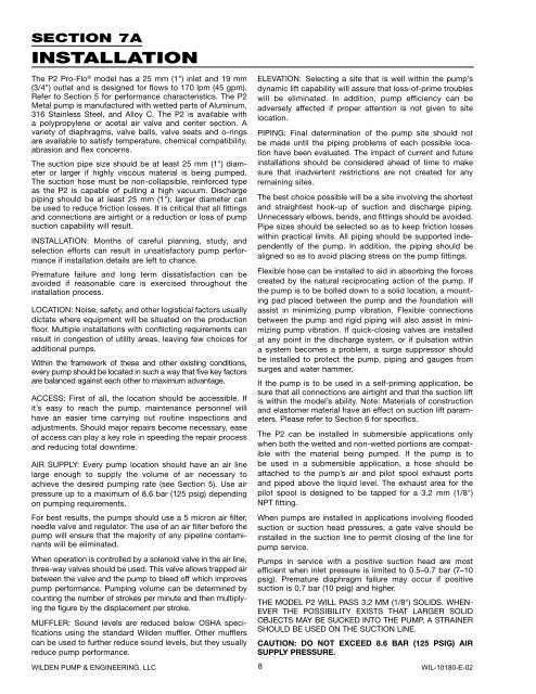
SECTION 7AINSTALLATIONThe <strong>P2</strong> Pro-Flo ® model has a <strong>25</strong> <strong>mm</strong> (1") inlet and 19 <strong>mm</strong>(3/4") outlet and is designed for flows to 170 lpm (45 gpm).Refer to Section 5 for performance characteristics. The <strong>P2</strong><strong>Metal</strong> pump is manufactured with wetted parts of Aluminum,316 Stainless Steel, and Alloy C. The <strong>P2</strong> is available witha polypropylene or acetal air valve and center section. Avariety of diaphragms, valve balls, valve seats and o-ringsare available to satisfy temperature, chemical compatibility,abrasion and flex concerns.The suction pipe size should be at least <strong>25</strong> <strong>mm</strong> (1") diameteror larger if highly viscous material is being pumped.The suction hose must be non-collapsible, reinforced typeas the <strong>P2</strong> is capable of pulling a high vacuum. Dischargepiping should be at least <strong>25</strong> <strong>mm</strong> (1"); larger diameter canbe used to reduce friction losses. It is critical that all fittingsand connections are airtight or a reduction or loss of pumpsuction capability will result.INSTALLATION: Months of careful planning, study, andselection efforts can result in unsatisfactory pump performanceif installation details are left to chance.Premature failure and long term dissatisfaction can beavoided if reasonable care is exercised throughout theinstallation process.LOCATION: Noise, safety, and other logistical factors usuallydictate where equipment will be situated on the productionfloor. Multiple installations with conflicting requirements canresult in congestion of utility areas, leaving few choices foradditional pumps.Within the framework of these and other existing conditions,every pump should be located in such a way that five key factorsare balanced against each other to maximum advantage.ACCESS: First of all, the location should be accessible. Ifit’s easy to reach the pump, maintenance personnel willhave an easier time carrying out routine inspections andadjustments. Should major repairs become necessary, easeof access can play a key role in speeding the repair processand reducing total downtime.AIR SUPPLY: Every pump location should have an air linelarge enough to supply the volume of air necessary toachieve the desired pumping rate (see Section 5). Use airpressure up to a maximum of 8.6 bar (1<strong>25</strong> psig) dependingon pumping requirements.For best results, the pumps should use a 5 micron air filter,needle valve and regulator. The use of an air filter before thepump will ensure that the majority of any pipeline contaminantswill be eliminated.When operation is controlled by a solenoid valve in the air line,three-way valves should be used. This valve allows trapped airbetween the valve and the pump to bleed off which improvespump performance. <strong>Pump</strong>ing volume can be determined bycounting the number of strokes per minute and then multiplyingthe figure by the displacement per stroke.MUFFLER: Sound levels are reduced below OSHA specificationsusing the standard Wilden muffler. Other mufflerscan be used to further reduce sound levels, but they usuallyreduce pump performance.WILDEN PUMP & ENGINEERING, LLCELEVATION: Selecting a site that is well within the pump’sdynamic lift capability will assure that loss-of-prime troubleswill be eliminated. In addition, pump efficiency can beadversely affected if proper attention is not given to sitelocation.PIPING: Final determination of the pump site should notbe made until the piping problems of each possible locationhave been evaluated. The impact of current and futureinstallations should be considered ahead of time to makesure that inadvertent restrictions are not created for anyremaining sites.The best choice possible will be a site involving the shortestand straightest hook-up of suction and discharge piping.Unnecessary elbows, bends, and fittings should be avoided.Pipe sizes should be selected so as to keep friction losseswithin practical limits. All piping should be supported independentlyof the pump. In addition, the piping should bealigned so as to avoid placing stress on the pump fittings.Flexible hose can be installed to aid in absorbing the forcescreated by the natural reciprocating action of the pump. Ifthe pump is to be bolted down to a solid location, a mountingpad placed between the pump and the foundation willassist in minimizing pump vibration. Flexible connectionsbetween the pump and rigid piping will also assist in minimizingpump vibration. If quick-closing valves are installedat any point in the discharge system, or if pulsation withina system becomes a problem, a surge suppressor shouldbe installed to protect the pump, piping and gauges fromsurges and water ha<strong>mm</strong>er.If the pump is to be used in a self-priming application, besure that all connections are airtight and that the suction liftis within the model’s ability. Note: Materials of constructionand elastomer material have an effect on suction lift parameters.Please refer to Section 6 for specifics.The <strong>P2</strong> can be installed in submersible applications onlywhen both the wetted and non-wetted portions are compatiblewith the material being pumped. If the pump is tobe used in a submersible application, a hose should beattached to the pump’s air and pilot spool exhaust portsand piped above the liquid level. The exhaust area for thepilot spool is designed to be tapped for a 3.2 <strong>mm</strong> (1/8")NPT fitting.When pumps are installed in applications involving floodedsuction or suction head pressures, a gate valve should beinstalled in the suction line to permit closing of the line forpump service.<strong>Pump</strong>s in service with a positive suction head are mostefficient when inlet pressure is limited to 0.5–0.7 bar (7–10psig). Premature diaphragm failure may occur if positivesuction is 0.7 bar (10 psig) and higher.THE MODEL <strong>P2</strong> WILL PASS 3.2 MM (1/8") SOLIDS. WHEN-EVER THE POSSIBILITY EXISTS THAT LARGER SOLIDOBJECTS MAY BE SUCKED INTO THE PUMP, A STRAINERSHOULD BE USED ON THE SUCTION LINE.CAUTION: DO NOT EXCEED 8.6 BAR (1<strong>25</strong> PSIG) AIRSUPPLY PRESSURE.8WIL-10180-E-02